Explore our multilingual library of applications that leverage the benefits of our applied technologies to address your challenges while creating impactful outcomes for your business.

Welcome to the Application Hub - Innovation Center.
This portal will help solution developers save time and resources by leveraging Rockwell Automation's technology and Solution Architect's expertise.

Showing {0}-{1} of {2} Results
Sort By:
No results found.
Portuguese
English
Aerospace
Airports & Airlines
Automotive & Tire
Cement
Chemical
Entertainment
Fiber & Textiles
Food & Beverage
Household & Personal Care
Hydrogen
Infrastructure
Life Sciences
Marine
Metals
Mining
Mining, Metals & Cement
Oil & Gas
Power Generation
Print & Publishing
Pulp & Paper
Semiconductor
Water Wastewater
Warehouse & Fulfillment
Mass Transit
Renewable Energy
Manufacturing
Waste Management
Implementer
Software
Smart Manufacturing
Safety Solutions
Emergency Stops for Machinery and Equipment Retrofit with Programmable Safety Relays
Emergency Stops for adaptation of Machines and Equipment with Programmable Safety Relays meeting requirements of Safety Standards such as ISO 13849-1 2008.
What is this for?
The objective of this Solution is the application of Emergency Stops, meeting up to Cat4/PLe according to ISO 13849-1:2008 standards. This application can be used on machines and equipment, emphasizing that the complete safety solution must be complied with.
General characteristics
Safety function for Emergency Stops through configurable Safety Relays, meeting the requirements of ISO 13849-1:2008.
Advantages
- Compliance with the main current safety standards.
- Use of certified safety solutions.
- Solution that enables expansions.
- Possibility of integration with control systems through the Ethernet/IP network.
Limitations and disadvantages
- The CCM Software must be updated to its latest version.
- This solution is part of the machine compliance process; the complete compliance process must be carried out.
Downloads
Please note: You will need to agree to the Terms & Conditions for each download.
Need Help?
If you need help with an application or have feedback from the Innovation Center, please contact us.
Is this useful to me?
Application already configured with the complete monitoring system for the emergency stop function using configurable safety relays.
How can I make it work?
Requirements: products, tools, prior knowledge.
- Hardware: Notebook and Bill of Materials
- Software: CCW Connected Components Workbench
Implementation Guide
Open the CCW Software; once opened, it will display an image similar to the one below:
emergency-stops-for-machinery-and-equipment-retrofit-with-programmable-safety-relays-img2
Select “Open Existing” and search for the application that was made available as “App Emergency Stop”. The location where the application is saved is selected by the user at the time of Download. After selecting the application, click “Open”.
emergency-stops-for-machinery-and-equipment-retrofit-with-programmable-safety-relays-img3
emergency-stops-for-machinery-and-equipment-retrofit-with-programmable-safety-relays-img4
After the application is loaded, click “Edit Logic” so that you can view the application logic.
emergency-stops-for-machinery-and-equipment-retrofit-with-programmable-safety-relays-img5
emergency-stops-for-machinery-and-equipment-retrofit-with-programmable-safety-relays-img6
After checking the application, simply click “Build” to evaluate whether there is any problem; once checked, the message “Build Succeeded” will be displayed.
emergency-stops-for-machinery-and-equipment-retrofit-with-programmable-safety-relays-img7
After checking, click “Download” and proceed with the application download process.
emergency-stops-for-machinery-and-equipment-retrofit-with-programmable-safety-relays-img8
Select the relay that is connected to the system, as shown in the image below.
emergency-stops-for-machinery-and-equipment-retrofit-with-programmable-safety-relays-img9
A confirmation will be requested to complete the Download process.
emergency-stops-for-machinery-and-equipment-retrofit-with-programmable-safety-relays-img10
After confirmation, it will indicate that the Download process has been completed.
emergency-stops-for-machinery-and-equipment-retrofit-with-programmable-safety-relays-img11
You can evaluate your program through On-Line verification, as shown in the image below.
emergency-stops-for-machinery-and-equipment-retrofit-with-programmable-safety-relays-img12
emergency-stops-for-machinery-and-equipment-retrofit-with-programmable-safety-relays-img2
sizing-a-complete-automation-system-connected-components_2.jpg
emergency-stops-for-machinery-and-equipment-retrofit-with-programmable-safety-relays-img4
emergency-stops-for-machinery-and-equipment-retrofit-with-programmable-safety-relays-img5
emergency-stops-for-machinery-and-equipment-retrofit-with-programmable-safety-relays-img6
emergency-stops-for-machinery-and-equipment-retrofit-with-programmable-safety-relays-img7
emergency-stops-for-machinery-and-equipment-retrofit-with-programmable-safety-relays-img8
emergency-stops-for-machinery-and-equipment-retrofit-with-programmable-safety-relays-img9
emergency-stops-for-machinery-and-equipment-retrofit-with-programmable-safety-relays-img10
emergency-stops-for-machinery-and-equipment-retrofit-with-programmable-safety-relays-img11
emergency-stops-for-machinery-and-equipment-retrofit-with-programmable-safety-relays-img12
Emergency Stops for Machinery and Equipment Retrofit with Programmable Safety Relays
Version 1.2 - June 2026
Emergency Stops for Machinery and Equipment Retrofit with Programmable Safety Relays
Emergency Stops for adaptation of Machines and Equipment with Programmable Safety Relays meeting requirements of Safety Standards such as ISO 13849-1 2008.
Tags:
Software
Languages:
Portuguese,
English
Deploy Time: 45 Minutes
English
Spanish
Portuguese
Aerospace
Airports & Airlines
Automotive & Tire
Cement
Chemical
Entertainment
Fiber & Textiles
Food & Beverage
Household & Personal Care
Hydrogen
Infrastructure
Life Sciences
Marine
Metals
Mining
Mining, Metals & Cement
Oil & Gas
Power Generation
Print & Publishing
Pulp & Paper
Semiconductor
Water Wastewater
Warehouse & Fulfillment
Mass Transit
Renewable Energy
Manufacturing
Waste Management
Implementer
Software
Software Evolution
Energy Monitoring using FT Optix
Faceplate creation, data transfer to HTML, HTML Sankey graph example, main objective being to monitor energy (WAGES)
What is this for?
The application was developed using FactoryTalk Optix software. The main objective of this application is to monitor energy (WAGES). In this example, we consider electrical energy, but this is the basis for developing the faceplates for the other WAGES. This solution uses Optix's ability to structure objects associated with data and graphics in dashboards.
Another objective is to be able to utilize visualization features, data management, and programming structures using C# and an example of HTML development with JS. The platform allows our operations to be at the forefront with technological solutions that help us facilitate the challenges of today's industry.
General Features
FactoryTalk Optix can help improve your processes, efficiency, and end products—all with one easily accessible tool. Leverage the levels of collaboration, scalability, and interoperability you need to achieve your digital transformation vision.
FT Optix stands out for its ability to connect to a wide variety of industrial devices and protocols such as OPC UA, Ethernet/IP, Profinet, Modbus, HTTPS, MQTT, and many others. This capability enables the integration and real-time monitoring of equipment from different manufacturers from a single IoT platform. Additionally, FactoryTalk Optix offers the ability to create data logs and save this information in a SQL database.
Using FT Optix as a visualization platform is essential; however, it also helps us send information to other structures or files, such as HTML web pages. In this case, we will use code to display a Sankey chart and analyze the energy in our example. However, you can use other charts that you can develop or search for as a complement. The idea is that you can identify how to send data in real time via FT Optix.
Advantages
- Use of structured code
- Connectivity flexibility
- Impact on development time
- Notifications based on the operating model
- Sending data to HTML web pages
- High reliability
- Compatible for implementation in your applications
- Flexibility and scalability
- Improved information flow
- Data optimization
- Real-time monitoring
- Information analysis
Downloads
Please note: You will need to agree to the Terms & Conditions for each download.
Need Help?
If you need help with an application or have feedback from the Innovation Center, please contact us.
Is this useful to me?
Being able to monitor assets or energy consumption is the first step in understanding the behavior of my equipment and my plant in general. The idea is to structure our energy consumption hierarchy as we do at our plant.
This application is the basis for developing the WAGES faceplates you need to monitor and can complement your real-time data analysis projects by sending data to graphs in HTML pages.
It is applicable to any industry or industrial segment where you want to begin analyzing and monitoring plant energy consumption.
This functionality can be replicated as many times as necessary in your projects, increasing the value of your products, optimizing implementation costs, and leveraging the data from your meters and instrumentation by monitoring and analyzing the data.
How can I make it work?
Requirements: products, tools, prior knowledge.
- Hardware
- Controllers/PLC compatible with FT Optix connectivity.
- Software
- FactoryTalk Optix (V1.5.6.0) or higher
- Background knowledge
- Basic knowledge FactoryTalk Optix, C#, html.
Implementation Guide
Download the program file to your FT Optix project folder.
Identify the application you want to use: FactoryTalk Optix.
Open the EnergyMonitoring file in the location where you downloaded it.
Make sure you have the .NET SDK x64 installed
https://dotnet.microsoft.com/en-us/download
Remember the path where you will install the Optix project.
energy-monitor-using-optix_Step 1
Step 2.1
Explore the application, open the main window, where you can see the elements that make up this demo.
energy-monitor-using-optix_Step 2_1
Step 2.2
Within the project view you will identify several Folders: Faceplates, Levels, Model, Variables, which we will be reviewing for the creation of the Faceplates and creation of the Navigation Panel.
energy-monitor-using-optix_Step 2_2
Creating a Faceplate - In this case, we will create the Faceplate for electrical energy monitoring.
Step 3.1
An object named Electric is created in the Model folder.
With the basic variables for an electric energy meter:
- name
- kw
- v
- i
energy-monitor-using-optix_Step 3_1
Step 3.2
In the Faceplates folder, create a Panel called ElectricFaceplate, which will be used to register all our electricity meters.
Generate an Alias associated with our Electric Object from the previous Step.
Each object, such as Label, Text Box, and Circular Gauge, is associated with the Alias variable it is to display.
energy-monitor-using-optix_Step 3_2
Create the objects for the meters and define the hierarchical structure of the electric energy meters we have.
Step 4.1
We must consider how many electricity meters we have (in this case, they are simulated; however, you can later associate them with a controller) and define how we will create our hierarchical structure.
In this example, we will have 17 meters:
Meter |
Name |
1 |
Sub1 |
2 |
Sub2 |
3 |
Line 1 |
4 |
Line 2 |
5 |
Line 3-1 |
6 |
Line 3-2 |
7 |
Aux |
8 |
Machine 1 |
9 |
Machine 2 |
10 |
Machine 3 |
11 |
Machine 4 |
12 |
Machine 5 |
13 |
MCC1 |
14 |
Compressor 1 |
15 |
Motor 1 |
16 |
Motor 2 |
17 |
Motor 3 |
With a hierarchy that will normally be the one you have in your electrical diagrams.
energy-monitor-using-optix_Step 4_1
Step 4.2
In the Model > Variables > Electric folder, all the Objects associated with the 17 meters we have considered are created, with the same structure that we have handled: name, kw, v, i.
energy-monitor-using-optix_Step 4_2
Step 5
We generate the screens of the different levels we have in the plant for energy measurement:
- Main
- Substations
- Areas: Lines and Auxiliar
- Machines, MCC, Compressor
- Motor (engine)
In the Levels folder we have the Panels for creating the different levels:
- Sub
- Areas
- Machines
- Devices
In this case, they are the Faceplates called ElectricFaceplate that we associate with each meter as appropriate with Meter Objects.
Step 5.1
For the Panel Sub we created two meters
- Sub1 associated meter1
- Sub2 associated meter2
energy-monitor-using-optix_Step 5_1
Step 5.2
For the Panel Area we created 5 meters:
- Line1 associated meter3
- Line2 associated meter4
- Line3_1 associated meter5
- Line3_2 associated meter6
- Auxiliars associated meter7
energy-monitor-using-optix_Step 5_2
And so on with the other Panels for the following levels and meters.
- Machines
- Devices
Data to the HTML webpage.
In the EnergyMonitoring > ProjectFiles > Sankey folder, we have our sample files for an HTML webpage to display data in the Sankey chart.
It's important to mention that the charts or libraries for the HTML webpage can be developed at your convenience or obtained from other templates. This is just an example to show how to send data to the webpage.
There are two files:
- Sankey.html – which we will be continually reviewing
- Template-Sankey.html – which helps us send data from Optix
Step 6.1
Sankey.html will be the file where we'll review the data to analyze it in the Sankey chart.
Here we see the structure of how our Sankey chart will be defined, practically according to our hierarchical levels.
energy-monitor-using-optix_Step 6_1
Step 6.2
Template-Sankey.html will be the file we'll use to build our HTML website with the Optix data.
We'll primarily name the variables $01, $02, and $17, associating them with the meters we created in our Optix application.
energy-monitor-using-optix_Step 6_2
Step 6.3
In our Optix application in the UI > MainWindow folder we will find our RuntimeChartHTML, which is a NetLogic to send the Optix data to the HTML web page, written in C#.
energy-monitor-using-optix_Step 6_3
Step 6.4
Reviewing the C# code for RuntimeChartHTML, we find the block where we associate the variables from our HTML page with the objects created in Optix.
$01 associated with the Optix data from the meter1/kw object.
Since what we will analyze on the HTML page in the Sankey chart is kw.
energy-monitor-using-optix_Step 6_4
We also created Faceplates to be able to manually structure our hierarchy in a Panel for the Energy layout.
energy-monitor-using-optix_Step 7
Step 8.1
Run the application and you'll be able to see the simulated energy consumption measurements (you can later link them to your real meters).
First, the energy layout.
energy-monitor-using-optix_Step 8_1
Step 8.2
Substation
energy-monitor-using-optix_Step 8_2
Step 8.3
Areas
energy-monitor-using-optix_Step 8_3
Step 8.4
Machines
energy-monitor-using-optix_Step 8_4
Step 8.5
Devices
energy-monitor-using-optix_Step 8_5
Step 8.6
Sankey HTML
energy-monitor-using-optix_Step 8_6
In your project folder, EnergyMonitoring > ProjectFiles > Sankey, you can open the Sankey.html page and view the data from a browser to analyze the Sankey chart.
You can view the data sent directly from Optix to the HTML page and analyze it.
energy-monitor-using-optix_Step 9
energy-monitor-using-optix_Step 1
energy-monitor-using-optix_Step 2_1
energy-monitor-using-optix_Step 2_2
energy-monitor-using-optix_Step 3_1
energy-monitor-using-optix_Step 3_2
energy-monitor-using-optix_Step 4_1
energy-monitor-using-optix_Step 4_2
energy-monitor-using-optix_Step 5_1
energy-monitor-using-optix_Step 5_2
energy-monitor-using-optix_Step 6_1
energy-monitor-using-optix_Step 6_2
energy-monitor-using-optix_Step 6_3
energy-monitor-using-optix_Step 6_4
energy-monitor-using-optix_Step 7
energy-monitor-using-optix_Step 8_1
energy-monitor-using-optix_Step 8_2
energy-monitor-using-optix_Step 8_3
energy-monitor-using-optix_Step 8_4
energy-monitor-using-optix_Step 8_5
energy-monitor-using-optix_Step 8_6
energy-monitor-using-optix_Step 9.png
Energy Monitoring using FT Optix
Version 1.2 - June 2026

Energy Monitoring using FT Optix
Faceplate creation, data transfer to HTML, HTML Sankey graph example, main objective being to monitor energy (WAGES)
Tags:
Software
Languages:
English,
Spanish,
Portuguese
Deploy Time: 60 Minutes
OEM
System Integrator
English
Portuguese
Spanish
Food & Beverage
Implementer
Manager
Hardware
Software
Machine & Equipment Builders
Multibelt Transport System
Designed to transport industry specially food and beverage, multibelt system is a storage/transport system used in many aplications where it requires movement of multiple products simultaneously from one point to another
What is this for?
The Multibelt system is a storage/transport system and consists of two or more independently driven belts. Each belt contains two or more trains (collators) that are built to carry a tray or built for a variable number of pockets. Trains vary in mechanical design. In the case of using a tray, the tray is placed inside the train in the loading position by any loading module. Products are fed from an infeed conveyor to the train at the filling position. If the feed train is full, it moves to the unloading position. If this is done, the train moves in positive rotation (recovery motion) behind the next train. This sequence guarantees a continuous flow of product in the filling area, while the other trains can be loaded with a tray and unloaded passing through the unloading position. The Multibelt equipment module can be configured with a large number of parameters, which are described in other chapters. A standardized interface for the load, supply and output module allows flexible adaptation.
General Features
The Multibelt System module concludes the following features:
• Multibelt storage sequence procedure for 2 axes (production mode)
• Automatic homing / reference move procedure
• Automatic synchronize move procedure
• Variable speed override adaption while production
• Jog function for each axis separately (service mode)
• Handling of multiple trains per belt
• Interface data handling to any other loading, infeed and outfeed module device
• Wide range of parameters to configure the module
Advantages:
The Mutibelt system has the advantage of being flexible and with the possibility of adaptation according to the application needs - number of collators (train).
From a software point of view, the system is relatively easy to implement using specific AddOn and Data DataTypes: Multibelt_AOI and Q_MAM_P (developed for this application, in order to reduce configuration, commissioning and startup time.
Limitations/Disadvantages
• Speed – Depends on the Drag Mechanism
• Number of mechanical elements - gears, belts
• Fixed space between cleats, if need change, mechanical change neededc
Is this useful for me?
In general, multibelt systems can be recommended to OEM manufacturers such as:
- Conveyor belt manufacturers
- Special machine manufacturers
- Palletizers manufacturers
- Packing machines manufacturers
Application areas:
Food, Manufacturing, Beverage
Benefits of applications with multibelt systems:
• Production gain and speed
• Increased dynamism in production
• 60% reduction in commissioning and startup time
• Easy of integration with devices: Robot, transfer devices
How can I make it work?
Requirements: Products, Tools, Previous Knowledge.
Hardware
- Kinetix 5300, Kinetix 5500, Kinetix 5700 with CIP Motion and CIP Sync
- PowerFlex 755 with Position control/ CIP Motion
- CompactLogix L18ERM or high
- Firmware revision 30 or high
Software
- Logix Design Studio 5000
- Program Multibelt_2Collators.ACD
- AddOn instructions: Multibelt_AOI, Q_MAP_P
Knowledge
Intermediate knowledge of programming and configuration in Logix Design Studio 5000 software:
- Ladder language (LD)
- Motion configuration.
Downloads
Please note: You will need to agree to the Terms & Conditions for each download.
Need Help?
If you need help with an application or have feedback from the Innovation Center, please contact us.
Installation Guide
Additional information is in the "Multibelt.pdf" document in Downloads >> GeneralFiles.zip
Step 1:
Instructions:
- Open program Multibelt_2Collators.ACD – This file is located inside the Generalfiles.zip package in the Downloads section.
- Initially you can use this program with Virtual Axis for tests. After that you can couple the virtual axis with physical axis using Motion Axis Gear (MAG).
Step 2
Motion Configuration:
- Configure the Axes Parameters Virtual (Collator_X_AV) and Physical (Collator_X_AP) . For Physical: Model of operation: Position Loop.
- Configure the virtual axes.
- Couple virtual axis with real – This function is already in the program example (Multibelt_2Collators.ACD) .
Step 3:
Configure Add-ons Data parameters:
1. MainTask > MainProgram > _01_Multibelt, Configure Add-on MultiBelt_AOI.
- Axis
- Axis Preceding
- Wagon Size
- Number of Wagons
- Loading Station Position
- Waiting Station Position
- Unloading Station Positions
2. MotionEventTask > Main_Motion_Rtn, configure Add-ON Q_MAM_P parameters (Setup and configure Train Data).
- Axis
- Axis Preceding
- Command Position
- Velocity
- Acceleration
- Deceleration
- Acceleration Jerk
- Decceleration Jerk
Step 4:
Download and commissioning
- You can use the Emulator (Factory Talk Logix Echo)
- For simulation, use MainTask > MainProgram > _02_Simulation program
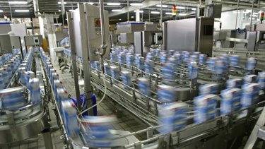
Multibelt Transport System
Designed to transport industry specially food and beverage, multibelt system is a storage/transport system used in many aplications where it requires movement of multiple products simultaneously from one point to another
Tags:
Hardware,
Software
Languages:
English,
Portuguese,
Spanish
Deploy Time: 30 Minutes
English
Portuguese
Spanish
Automotive & Tire
Cement
Chemical
Fiber & Textiles
Food & Beverage
Household & Personal Care
Hydrogen
Life Sciences
Marine
Metals
Mining
Mining, Metals & Cement
Oil & Gas
Power Generation
Pulp & Paper
Water Wastewater
Warehouse & Fulfillment
Implementer
Software
Environmental Solutions
Process Solutions
Sustainability
Turbomachinery Control Solutions
Boiler Efficiency Library
A library to measure the efficiency of a boiler in real time using existing instrumentation in an Allen Bradley control system.
What is this for?
The objective of creating a standard Boiler Efficiency library is to gather knowledge from experience and applications utilizing the best approaches to provide features that will be selected based on the detailed requirements of the project scope. Control, process design, and the configuration approach will utilize a PlantPAx based control system that will be used with standard Boiler Efficiency applications. It is also desired for the controller to be flexible and allow integration of custom requirements and expansion as future technological developments are realized through industries.
The vision is to allow the user to select specific requirements and procedures, including and configuration capabilities, to meet the needs of the required mixing application.
Is this useful for me?
Currently, there is no way to calculate Boiler Efficiency in a standardized way. A standard library with flexibility allows for the same basic building blocks to be utilized.
By standardizing the Boiler Efficiency library, it may be used for multiple industries (F&B, Chem, Life Science, Home & Personal Care) across the globe. This standard will also be able to assist in cost benefit to the organization by lowering the engineer labor to create basic functionality.
Capturing of industry specific knowledge. Future go-to-market features for sales of Plant Pax application. Financial and labor savings are unknown currently. However, reduced development time is expected due to the ability of tool to create basic functionality.
How can I make it work?
User will enter Boiler system inputs based on standard instrumentation typically used in Boilers.
This first version allows you to have real time efficiency in a Rockwell Automation control system, just import and configure the AOI and the Display, add it in your application and that's it.
System requirements of app:
| Item | Requirement | Version |
|---|---|---|
| 1 | Tool will be built using Steam properties libraries of PlantPAx | 4.x – 5.x |
| 2 | FactoryTalk View SE/ME | 12.00 |
| 3 | Studio 5000 | 21 and above |
Process variables will need to be able to be configured including input signal, scaling, and units.
| Item | Instrumentation |
|---|---|
| Temperature (Steam and Water) | Type:
|
| Flow (Steam, Water, Fuel) | Type:
|
| Pressure (Steam, Water) | Type:
|
Knowledge required
Basic knowledge of programming and configuration in Studio 5000 Logix Designer® software and FactoryTalk® View Site Edition Studio.
Downloads
Please note: You will need to agree to the Terms & Conditions for each download.
Need Help?
If you need help with an application or have feedback from the Innovation Center, please contact us.
Installation Guide
Step 1:
1. Import file L5X for routine according with the programing language to use:
- Calc_Boiler_Efficiency_FB_Routine_FBD. L5X for Function Block.
- Calc_Boiler_Efficiency_LD_Routine_RLL.L5X for Ladder.
Note: Please read the instructions in the program comments
Step 2
Import the Global Object in FTView SE Application.
- Boiler efficiency.ggfx.
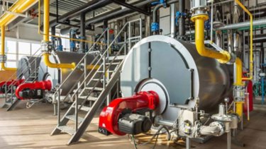
Boiler Efficiency Library
A library to measure the efficiency of a boiler in real time using existing instrumentation in an Allen Bradley control system.
Tags:
Software
Languages:
English,
Portuguese,
Spanish
Deploy Time: 60 Minutes
English
Portuguese
Spanish
Automotive & Tire
Cement
Chemical
Fiber & Textiles
Food & Beverage
Household & Personal Care
Hydrogen
Life Sciences
Marine
Metals
Mining
Mining, Metals & Cement
Oil & Gas
Power Generation
Pulp & Paper
Water Wastewater
Warehouse & Fulfillment
Implementer
Software
Industrial Automation & Control
Process Solutions
Simple On-Off Control for First Orders and Overdamped Systems
Bang-Bang Control: an easy to program and calibrate first order plant control when output of the system is on-off actuator.
What is this for?
The objective of this document is to present an easy to program and calibrate first order plant control when output of the system is on-off actuator. This algorithm is based on Bang-Bang Control which uses hysteresis to turn on and off the output of the control with an enhancement of a first order filter in an inner feedback loop to increase modulation of the output.
The type of outputs that this control may drive are:
- Solenoid Valves.
- Motorized Valves with 2 positions (Open/Close).
1. Solid State Relays (To drive heating resistors).
2. Electromechanical Contactors.
This solution has been tested in physical thermal heating and heating/cooling systems described in the tools and prerequisites section (see below) as the test equipment, and level control systems (Tested in industrial system not shown here) where we have inlet and outlet flow.
Is this useful for me?
The bang-bang principle of operation is the on/off control with hysteresis, but we have added a feedback inner loop at the on/off output through a first order filter.
The ultimate effect of the Feedback First Order filter in the Bang-Bang Control is to compensate for the dead time it takes between from the actuator that affects the measured variable and the sensor to report actual measurement.
With the feedback filter, the oscillation at the control output will begin earlier than if it only had the hysteresis comparator hence limiting the amount of heat deliver to the tank helping to avoid overshoot as the heated liquid arrives to the sensor.
This algorithm can replace a Proportional-Integral control loop that needs to be connected to a time proportional output, it is simpler to tune and has less parameters to setup.
Note: We suggest using this algorithm for first order systems and only critically damped and overdamped (ζ≥1) second order systems. Undamped system may produce undesirable oscillations that may have unexpected behavior.
How can I make it work?
Previous knowledge:
- Enhanced Bang-Bang Algorithm theory of operation.
- Definition of a First Order and Second Order Critically Damped or Overdamped System.
(Full document available here)
The block diagram for the enhanced Bang-Bang control algorithm is shown in Figure 1:
The bang-bang principle of operation is the on/off control with hysteresis, as the diagram shows the system will turn on when the input [e2] is greater than H but, it will hold on until [e2] is less than L.
Normally this is all the bang-bang functionality, but we have added a feedback inner loop at the on/off output through a first order filter. This filter is implemented mathematically in the algorithm.
This first order filter (FOF) will receive the status of the bang-bang (BB) (hysteresis) output block that is a 1 (one) or 0 (cero) depending if the output is on or off. The result will be a capacitance charge or discharge depending on the state of the Bang-Bang block output. The tendence of the FOF output will be K when the BB output is on and will tend to cero when the output is off.
The output of the FOF is subtracted of the error [e] producing a reduced [e2] that will tend to K, this means that when the error (e=SP-PV) is greater for enough time, e2 will tend to e-Kr, therefore e2 will be greater than H turning the output of the BB to on.
The final control element will stay open until the plant reaches the difference stated by e2 ≤ L the output of the BB will turn off even when the plant has not yet reached the Setpoint, but then the feedback filter will begin a discharge provoking an increase on e2. The discharge will continue until e2 reaches H that will turn again the output of BB.
The process will continue to cycle between on/off until the PV reaches SP.
Tunning the Bang-Bang
Tunning method is quite intuitive. But is best to begin with small gain in the feedback filter and few units of error to turn on the control and few units to turn off the control. It can begin centered over cero. For example, start with [H = 0.5% of the control variable] and [L=- 0.5% of the control variable]. Make K=0 to see how the system reacts to a pure bang-bang.
The sample time should be equal to the periodic function call for the Bang-Bang function. This parameter is important because it will determine the system timing for the following steps.
Check the overshoot after the system stabilizes, make [K] equal to overshoot and [Tao] equal to the dead time (t0) to estimate this time (does not have to be precise) measure the time between the output of the actuator activates and when you can see a perceivable change of 0.5% in the control variable.
This will set up the Bang-Bang for the first pass tunning.
By observing the system capacity, you may reduce the gap between [H] and [L] to reduce magnitude of the fluctuations around the set point [SP].
You can also reduce or increase the on/off period by modifying [Tao] on the control. This will enhance the precision of the system output but will create and increase of on/off cycles in the actuator.
Be aware that if the actuator has a mechanical operation such as a relay, contactor or solenoid valve, the life of the actuator will be inverse of the number of on/off cycles, so you will need to make a trade off among life of the actuator and precision of the control.
Cooling Bang-Bang (Actuator to decrease the control variable)
The algorithm to decrease the control variable such as cooling in a heated tank or pressure release valve in a pressure tank is very similar to the heating diagram but with some changes as shown in figure 2:
The difference in the algorithm is that the decrease output is multiplied by -1 before feeding the input of the inner loop filter. The control different parameters, now the hysteresis turns on the decrease actuator when the e2 is less than de SP at DecON point and will turn off the decrease actuator when the e2 is greater than DecOFF point.
Heating and cooling Bang-Bang
The last case for Bang-Bang is when you have both actuators for the same system, this is the case of application such as chrome plating or galvanizing where the systems need to be at a certain temperature to begin the process but once the process is in operation, the process generates more heat due to the electro plating current and hence needs to be cooled.
In this case we need to use the Bang-Bang in dual mode as shown in figure 3:
As you can see in figure 8, we have 2 hysteresis, one to drive the increase actuator and one to drive the decrease actuator. The key to tune this option is to make sure that the [DecON] parameter is always less than the [IncOn] and is preferable that the off point of both parameters does not cross each other. Is preferable that both hysteresis are set up as mutually exclusive.
Tools & prerequisites
Software:
- Studio 5000 Logix Designer v35.
- FactoryTalk View ME v12.00.00.
Hardware:
- ControlLogix Logix (1756-L83) FW v35.
- CompactLogix I/O Adapter (5069-AEN2TR).
- CompactLogix Universal Analog Input Card (5069-IY4).
- CompactLogix 16 24VDC output card (5069-OB16F).
- PanelView Plus 7 Performance 700 (2711P-T7C22A9P).
Test System Components:
- 1 Pc 8 liters aquarium.
- 1 pc RTD PT100 Temperature Sensor.
- 1 pc Solid State Relay 24 VDC input coil / 125 VAC output.
- 1 pc 400 watts heating resistor.
Files:
- BB.acd Logix Designer Addon Instruction
Inputs & Outputs for the testing system.
The input outputs used are:
- 1 PT100 RTD temperature sensor connected to Remote Compact I/O input in slot 3 input 0 (5069-IY4). Controller tag: Compact_Ethernet_Adapter:3:I.Ch00.Data.
- 2 DC output connected to 24 DC output card in Remote Compact I/O in slot 2 output 0 & 1. Compact_Ethernet_Adapter:2:O.Pt00.Data & Compact_Ethernet_Adapter:2:O.Pt01.Data.
Bang-Bang Add On Instruction (AOI).
The Bang-Bang Add On Instruction contains the instruction parameters, input variables and output variables to make the control work as well as the logic. The parameters that are input and output are shown in the faceplate made for Panelview Plus 7.
AOI Structure
The AOI instruction has a defined data type to name each control system by its unique name. In the case of this example the name of the system is “Acuarium” that has the {aoi_Bang_Bang} data type.
Enable/Disable Parameters:
Parameter List and description.
[BB_is_ON] Boolean input variable to turn the control to ON or OFF.
[Has_inc_element] Boolean input to indicate if control has variable increase actuator.
[Has_dec_element] Boolean input to indicate if control has variable decrease actuator.
Operation parameters:
[PV] Process variable: This is a real floating-point parameter. You should assign the scaled variable of the input card to this variable.
[SP] Set Point: This is a real floating-point parameter. This variable will be set in the HMI or any input device that sets the reference for the control.
Calibration parameters:
[Inc_On] Real floating-point parameter. This is part of the hysteresis of the Bang-Bang that if the input error to the hysteresis greater than this value, the output to the increase the control variable is turned on.
[Inc_Off] Real floating-point parameter. This is part of the hysteresis of the Bang-Bang that if the input error to the hysteresis is less than this value, the output to the increase the control variable is turned off.
[Dec_On] Real floating-point parameter. This is part of the hysteresis of the Bang-Bang that if the input error to the hysteresis is less than this value, the output to the decrease the control variable is turned on.
[Dec_Off] Real floating-point parameter. This is part of the hysteresis of the Bang-Bang that if the input error to the hysteresis is greater than this value, the output to the decrease the control variable is turned off.
[tsample] Real floating-point parameter. This parameter should be equal to the time defined for the scan time of the periodic task for the Bang-Bang.
[Tao] Real floating-point parameter. This is the time constant in seconds for the first order filter at the inner loop feedback.
[K] Real floating-point parameter. This is the gain that the output of the first order system will tend after long period of time (normally 7 times Tao). If K = 3, then after 7 times Tao, the filter output will be near 3.
Monitoring Parameters
[e] Real floating-point variable. This indicates the difference between the setpoint and the process variable ([e] = [SP] – [PV]).
[e2] Real floating-point variable. Is the difference between the error [e] and the output of the first order filter [FB_Filter_Out].
[FB_Filter_In] Real floating-point variable. Is the input to the feedback filter which is the result of adding [INC_OUT] – [DEC_OUT] output parameters. These parameters are the actual outputs to actuator elements. Because [INC_OUT] and [DEC_OUT] parameters are Boolean, to add these parameters is required to use integer variables before assigning to the Filter input.
[FB_Filter_Out] Real floating-point variable. Is the output of the feedback filter which is the result of the digitalization of the transfer function of a first order system. For simplification purposes, the first order differential equation is transformed to digital sampling with Euler method.
The filter equation is as follows:
Output Parameters
[INC_OUT] Boolean Output Parameter. This is the output that must be connected to the output card to drive the Increase control variable actuator.
[DEC_OUT] Boolean Output Parameter. This is the output that must be connected to the output card to drive the decrease control variable actuator.
AOI internal variables
The Add On Instruction has other internal variables required to execute the instruction such as conversion from Boolean to Integer. We will not describe each of these variables in this document as the AOI instruction is open for reviewing and editing.
Panelview plus 7 screens
Panelview 7 machine edition screen is provided as face plate for the Bang-Bang Control.
The face plate is provided as a sample for a system and is included in the documentation package.
Previous Knowledge
Definition of a First Order and Second Order Critically Damped or Overdamped System. You can find the complete document here.
Downloads
Please note: You will need to agree to the Terms & Conditions for each download.
Need Help?
If you need help with an application or have feedback from the Innovation Center, please contact us.
Installation Guide
To implement the Add On Instruction check the following steps.
Studio 5000 AOI
Step 1:
Extract files from BB.ZIP into your working directory
Step 2:
Open file BB.acd into Studio 5000
Step 3:
Open the project where you want to use the Bang-Bang (it is assumed that the I/O mapping of your project is already done).
Step 4:
Highlight Select the aoi_Bang_Bang instruction under Assets menu in the controller organizer section of the Logix Designer.
Step 5:
Right click the mouse and select Copy as shown if Figure.
Step 6:
Go to the program you want to use the Bang-Bang and under Assets, highlight select the folder Add-On Instructions.
Step 7:
Verify that your target program has the new pasted AOI and under data type you should also have a new structure under Add-On-Defined.
Step 8:
Create a periodic task where you want to use the Bang-Bang Control or copy and paste the sample task from the BB.acd program. If you choose to copy the periodic task it must be done in 2 steps:
a. Select the Bang_Bang (10ms) Task, right click the mouse button and select copy.
b. Go to your target program and under Task folder right click select paste. The periodic task will be created in the target program.
c. From the BB.acd program under Bang_Bang (10ms) task right click select the BB_Logic routine and select copy.
d. In the target program select Bang_Bang (10ms) and right click to paste the logic.
Step 9:
Under Controller Tags define a new variable “Acuarium” (because this is the name of the system in the BB_Logic routine.
Step 10:
In the BB_Logic routine in the program named {IOAssignments_n_Scaling}, change the I/O Analog Input Address to match your project. Also change the Digital output to the Control Actuators to match your project.
Step 11:
Your Bang-Bang should be ready to work in your target program.
View Studio ME
To use the template for PanelView Plus 7 Performance, you will need to recover the project from the .mer file into the Studio 5000 View ME.
Step 12:
From the zip file unzip the file named PV7P_BB.mer (Remember this file is in version 12 for ViewME).
Step 13:
Use Factory Talk ViewME Application Manager from the tools menu within the FactoryTalk ViewME application.
Step 14:
Select “Restore runtime application.”
Step 15:
Select the file BB.mer file.
Step 16:
Select Open application and the application should be restored.
You can also find many videos on how to restore a .mer application to recover

Simple On-Off Control for First Orders and Overdamped Systems
Bang-Bang Control: an easy to program and calibrate first order plant control when output of the system is on-off actuator.
Tags:
Software
Languages:
English,
Portuguese,
Spanish
Deploy Time: 60 Minutes
Portuguese
English
Spanish
Aerospace
Airports & Airlines
Automotive & Tire
Cement
Chemical
Entertainment
Fiber & Textiles
Food & Beverage
Household & Personal Care
Hydrogen
Infrastructure
Life Sciences
Marine
Metals
Mining
Mining, Metals & Cement
Oil & Gas
Power Generation
Print & Publishing
Pulp & Paper
Semiconductor
Water Wastewater
Warehouse & Fulfillment
Mass Transit
Renewable Energy
Manufacturing
Waste Management
Implementer
Hardware
Software
Industrial Automation & Control
Emonitor: event-based date extraction from Dynamix 1444.
Procedure for extracting data from the Dynamix 1444 upon the occurrence of a specific event.
What is this for?
This application allows configuring data collection from the Dynamix 1444 so that it occurs upon a previously selected event.
General Features
This development includes:
- Program configuration in Studio 5000
- Procedure for Emonitor EEM
- Procedure for Scheduler
Advantages
- Allow limiting data collection to a defined period
- Simplifies configuration for extraction in Emonitor
Limitations / Disadvantages
- Limited to “Live Data Extraction”; does not support “Demand Data Extraction”
- Limited to Emonitor versions 4.1 and above
Is this useful to me?
Yes, if you need to extract data from 1444 only when a specific event occurs (e.g., presence of elements on a conveyor belt).
Application Areas: Can be applied in vibration monitoring environments for rotating machinery.
Downloads
Please note: You will need to agree to the Terms & Conditions for each download.
Need Help?
If you need help with an application or have feedback from the Innovation Center, please contact us.
How do you make it work?
Requirements: products, tools, prior knowledge.
Hardware
- Logix Controllers
- Dynamix 1444
Software
- Studio 5000 (program developed in version 37)
- Emonitor, version 4.1 or higher
Knowledge
- Basic programming and configuration knowledge in: Studio 5000, Ladder Logic and Emonitor.
Implementation Guide
Studio 5000 Program.
Emonitor-event-based-date-extraction-from-Dynamix-1444_step1_image1
Create a program in Studio 5000 and add the 1444 module.
Emonitor-event-based-date-extraction-from-Dynamix-1444_step1_image2
Configure the Dynamix 1444 for use with a single 1443-ACC-GP-T accelerometer.
- Set the module “personality” to operate at 4 kHz per channel.
Emonitor-event-based-date-extraction-from-Dynamix-1444_step1_image3
- Select the measurements to be sent by the Dynamix 1444 module.
Emonitor-event-based-date-extraction-from-Dynamix-1444_step1_image4
- Select the measurements obtained from the accelerometer signal.
- Configure the accelerometer.
Emonitor-event-based-date-extraction-from-Dynamix-1444_step1_image6
- Configure reference speeds.
Emonitor-event-based-date-extraction-from-Dynamix-1444_step1_image5
Emonitor-event-based-date-extraction-from-Dynamix-1444_step1_image7
- Configure channel 0 filters.
Emonitor-event-based-date-extraction-from-Dynamix-1444_step1_image8
- Configure Overall measurements.
Emonitor-event-based-date-extraction-from-Dynamix-1444_step1_image9
- Configure the measurements to be extracted by Emonitor.
Emonitor-event-based-date-extraction-from-Dynamix-1444_step1_image10
- Configure the measurements to be extracted by Emonitor.
Emonitor-event-based-date-extraction-from-Dynamix-1444_step1_image11
- Configure FFT analysis bands.
Download and run the program.
Emonitor-event-based-date-extraction-from-Dynamix-1444_step1_image13
Add logic for the activation tag.
- A boolean tag will be configured to initiate data collection.
- This tag must be a “local tag”.
Emonitor-event-based-date-extraction-from-Dynamix-1444_step1_image12
Emonitor CMS Configuration.
Create the equipment where data will be collected.
Process to add a plant, production line, and machine to the database:
- Start Emonitor CMS.
- Open the Database window by selecting Window > Database and choose the Database Setup view in the Select View dialog box.
- The view shows the Hierarchy pane on the left and the Location pane on the right. To add a plant, select the disk icon in the Hierarchy pane and press Insert. The cursor will appear in a box next to a new hierarchy item at the bottom of the Hierarchy tree
Emonitor-event-based-date-extraction-from-Dynamix-1444_step2_image1
EEM Configuration.
Emonitor-event-based-date-extraction-from-Dynamix-1444_step3_image1
Open the EmonitorEEM tool.
- Log in with the following credentials:
- Username: admin
- Password: password
Emonitor-event-based-date-extraction-from-Dynamix-1444_step3_image2
- Create a new extraction by selecting “Triggered”.
Emonitor-event-based-date-extraction-from-Dynamix-1444_step3_image3
- Create an OPC topic (in RSLinx) and use it:
Emonitor-event-based-date-extraction-from-Dynamix-1444_step3_image4
- Complete the field with the Studio 5000 program where the “trigger” tag is located.
Emonitor-event-based-date-extraction-from-Dynamix-1444_step3_image5
- Create the extraction:
Emonitor-event-based-date-extraction-from-Dynamix-1444_step3_image6
- Link the extraction to the Dynamix 1444 module.
Emonitor-event-based-date-extraction-from-Dynamix-1444_step3_image7
- Map the available measurements from channel 0 to the machine configured in Emonitor CMS hierarchy (use “Auto Map”).
Emonitor-event-based-date-extraction-from-Dynamix-1444_step3_image8
- Configure the “trigger” using the designated tag:
Emonitor-event-based-date-extraction-from-Dynamix-1444_step3_image9
- Assign the mapped measurements to the extraction created:
Emonitor-event-based-date-extraction-from-Dynamix-1444_step3_image10
- Link to the Dynamix 1444 module:
Note: It is no longer necessary to configure the extraction interval.
Emonitor-event-based-date-extraction-from-Dynamix-1444_step3_image12
- Save the extraction:
Emonitor-event-based-date-extraction-from-Dynamix-1444_step3_image11
Emonitor-event-based-date-extraction-from-Dynamix-1444_step3_image13
- Start the extraction:
Scheduler Configuration.
Verify that the following services are active:
- EmonitorDDM.
- EmonitorScheduler.
- RSLinx Classic.
Emonitor-event-based-date-extraction-from-Dynamix-1444_step4_image1
- Open the Scheduler tool and create a new profile.
Emonitor-event-based-date-extraction-from-Dynamix-1444_step4_image2
- Configure the executable and command line.
Emonitor-event-based-date-extraction-from-Dynamix-1444_step4_image3
- Set the extraction frequency:
Emonitor-event-based-date-extraction-from-Dynamix-1444_step4_image1
- Ready for extraction:
Emonitor-event-based-date-extraction-from-Dynamix-1444_step4_image5
Emonitor-event-based-date-extraction-from-Dynamix-1444_step1_image1
Emonitor-event-based-date-extraction-from-Dynamix-1444_step1_image2
Emonitor-event-based-date-extraction-from-Dynamix-1444_step1_image3
Emonitor-event-based-date-extraction-from-Dynamix-1444_step1_image4
Emonitor-event-based-date-extraction-from-Dynamix-1444_step1_image5
Emonitor-event-based-date-extraction-from-Dynamix-1444_step1_image6
Emonitor-event-based-date-extraction-from-Dynamix-1444_step1_image7
Emonitor-event-based-date-extraction-from-Dynamix-1444_step1_image8
Emonitor-event-based-date-extraction-from-Dynamix-1444_step1_image9
Emonitor-event-based-date-extraction-from-Dynamix-1444_step1_image10
Emonitor-event-based-date-extraction-from-Dynamix-1444_step1_image11
Emonitor-event-based-date-extraction-from-Dynamix-1444_step1_image12
Emonitor-event-based-date-extraction-from-Dynamix-1444_step1_image13
Emonitor-event-based-date-extraction-from-Dynamix-1444_step2_image1
Emonitor-event-based-date-extraction-from-Dynamix-1444_step3_image1
Emonitor-event-based-date-extraction-from-Dynamix-1444_step3_image2
Emonitor-event-based-date-extraction-from-Dynamix-1444_step3_image3
Emonitor-event-based-date-extraction-from-Dynamix-1444_step3_image4
Emonitor-event-based-date-extraction-from-Dynamix-1444_step3_image5
Emonitor-event-based-date-extraction-from-Dynamix-1444_step3_image6
Emonitor-event-based-date-extraction-from-Dynamix-1444_step3_image7
Emonitor-event-based-date-extraction-from-Dynamix-1444_step3_image8
Emonitor-event-based-date-extraction-from-Dynamix-1444_step3_image9
Emonitor-event-based-date-extraction-from-Dynamix-1444_step3_image10
Emonitor-event-based-date-extraction-from-Dynamix-1444_step3_image11
Emonitor-event-based-date-extraction-from-Dynamix-1444_step3_image12
Emonitor-event-based-date-extraction-from-Dynamix-1444_step3_image13
Emonitor-event-based-date-extraction-from-Dynamix-1444_step4_image1
Emonitor-event-based-date-extraction-from-Dynamix-1444_step4_image2
Emonitor-event-based-date-extraction-from-Dynamix-1444_step4_image3
Emonitor-event-based-date-extraction-from-Dynamix-1444_step4_image4
Emonitor-event-based-date-extraction-from-Dynamix-1444_step4_image5
factorytalk-optix-condition-monitoring-dashboards_16x9-optix_monitoreo_step1_image17.jpg
Emonitor: event-based date extraction from Dynamix 1444
Version 1.0 - June 2026
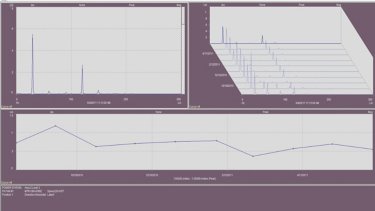
Emonitor: event-based date extraction from Dynamix 1444.
Procedure for extracting data from the Dynamix 1444 upon the occurrence of a specific event.
Tags:
Hardware,
Software
Languages:
Portuguese,
English,
Spanish
Deploy Time: 60 Minutes
OEM
System Integrator
English
Portuguese
Spanish
Food & Beverage
Cement
Chemical
Fiber & Textiles
Mining
Implementer
Manager
Software
Consulting & Integration Services
Industrial Automation & Control
LOTO - LockOut and TagOut
How to make an efficient and safe digital electrical lock on electrical panels?
What is this for?
LOTO consists of a functionality available in Factory Talk View Studio SE and Studio 5000 that allows the safe, direct and indirect digital blocking of equipment in electrical panels, drawers and CMM, controlled by duly accredited users, increasing safety for operators and maintenance people.
General Features
The electrical lock consists of the shutdown of the component responsible for energizing a circuit (usually a circuit breaker) and inserting a padlock into this disconnected circuit breaker, so that it cannot be reconnected by another person during the entire maintenance.
In this way, the electrical block prevents anyone from being able to access and/or maneuver this component and from energizing a certain circuit, where workers are intervening in maintenance.
Locks can be used individually or collectively, through multiplier devices, in situations where multiple teams are working on the same equipment, but on different service fronts. This way, the machine will only be energized when all team locks are removed.
After all, it is important to emphasize that the blockage in the electrical circuits must be carried out mainly in the power circuits and can be complemented with the shutdown of the control circuit.
Next to the locking device, a signaling card is also inserted, usually containing the photo of the person responsible for the lock, its function and allocation sector, in addition to the name of the circuit or equipment that was blocked by it.
Therefore, the purpose of the signal card is to visually alert people not involved in the process that the equipment is blocked for some reason and cannot under any circumstances be energized.
Advantages:
LOTO with Factory Talk View Studio and Studio 5000 make it simple and safe to lock panels, CMM drawers, specific equipment such as valves, motors and instruments in the field.
- Time for configuration
- Request
- Authorization by the area owner
- Indication of padlock placement
- Indication of zero energy test by the area owner
- Removal of the blockade by the owner of the area
- Block outputs
- Label placement
- Label withdrawal
- Authorization by the General Manager
- Break by the maintainer
- More protection for operators and maintenance people
Is this useful for me?
In general, LOTO is recommended specially for automation process control where it requires the need to block equipments for maintenance and repairs.
- Cement process
- Food and Beverage process
- Chemical process
- Steel industry
- Mining Companies
Application areas:
Cement, Food and Beverage, Chemical, Steel, Mining.
Benefits of applications with LOTO systems:
- Secure digital lock management
- Treacebility
- Lock by area and equipment
- SQL Server database for record datas
How can I make it work?
Hardware
- Logix Controllers (ControlLogix / CompactLogix)
Software
- Factorytalk View SE Enterprise v13 or higher
- Studio 5000 Logix Desing v35 or higher
- SQL express (ou SQL Server para FTAlarm&Event)
- FactoryTalk Logix Echo V2 (or Physical Controller)P
Knowledge
Intermediate knowledge of programming and configuration in Logix Design Studio 5000 software:
- Studio 5000 - Ladder language (LD)
- Studio 5000 - Function Block Diagram (FBD)
- Factory Talk View Studio
- Factory Talk Echo
Downloads
Please note: You will need to agree to the Terms & Conditions for each download.
Need Help?
If you need help with an application or have feedback from the Innovation Center, please contact us.
Installation Guide
Step 1:
Studio 5000 Logix Design:
- Download files documentation available
- Open FILES> LOTO_Aplication Referency_en_EN.docx – Use this document as referency
- Studio 5000 Logix Desing, Open program PController_FTEcho.ACD in Files/CS – Control Strategie
- Import the 32Dis Card (to exemplify using the "Connection" where we can modify with the controller running without stopping)
- Slow/Slow Program, import routine MTR_Lock_Routine_FBD.L5X.
Step 2
Factory Talk Logix Echo:
- Open FactoryTalk Logix Echo - ControlLogix 5580 Emulator V35
- Add the controller (ACD) PController_FTEcho.ACD
- In Studio 5000, Who Active, Select Emulate 5580 Controller and Download the program and Run Mode.
Step 3:
Factory Talk SE:
- Open FactoryTalk View SE Application Manager
- Restore an Archive (menu), FILES\Backup .Apb – Distribuited Application, Select LOTO_2023_01.apb application. Check the name of your machine (Primary Host)
- Open Application in FT View Studio (Network Distributed)
- Import alarm configuration from Excel file. FILES\Alarms Exported > LOTO_2023_01_FTAE_AlarmExport.xls
- Configure the communication setup
- Add Database in System\Connections\Databases.
Step 4:
Factory Talk SE – Application:
- Where we have a folder called LOTO, the sample screens "001_Coluna 1-8" for use in the application
- With the "001_Coluna 1-8" screen open, see that each column contains its devices in each drawer, thus setting up according to your CCM
- Add Engine lock MTR001 in Column 3 (ra-blk) equip lock and hold and drag the "GO_EqpLockLOTO" object to Column 3.
Step 5:
Factory Talk SE – Client Application:
- Click on the FactoryTalk View Client file in the folder (if I need to edit to work, please click with the right and Edit). We have in the Example of the PlantPAx DCS template where it can be used.
- Column 1-8" button opens the screen with the CCM
- See that automatically the column we set up appears already configured
- Type as example "RAZAO 01" and click ENTER to start Digital Lock
- "Request", check to follow the next step
- Follow the steps and see that there is the possibility of checking STATUS (reason) for the following items (Autoruzar and Zero Energia)
- In the Etiquete we have as shown the option below and in the lock /padlock icon for the execution of the job or the break of the same all recorded in the events). In the Advanced icon, check the other available settings. For modification of descriptions, it can be done via faceplate or via controller in aoi MTR001_lock
- After performing the job, click "Unlock" the faceplate will return to normal mode (all clean action)
- To Check all the steps taken for blocking, users, comments, click "Events" and navigate each line for detailing
LOTO - LockOut and TagOut
How to make an efficient and safe digital electrical lock on electrical panels?
Tags:
Software
Languages:
English,
Portuguese,
Spanish
Deploy Time: 240 Minutes
English
Spanish
Aerospace
Automotive & Tire
Cement
Chemical
Entertainment
Fiber & Textiles
Food & Beverage
Household & Personal Care
Hydrogen
Infrastructure
Life Sciences
Marine
Metals
Mining
Mining, Metals & Cement
Oil & Gas
Power Generation
Print & Publishing
Pulp & Paper
Semiconductor
Water Wastewater
Warehouse & Fulfillment
Mass Transit
Renewable Energy
Implementer
Software
Industrial Automation & Control
Flying Shear Application
Their unique design allows product to be cut on the fly as it moves past the shear. Productivity is optimal because the belt never stops during the cut.
How can I make it work?
Downloads
Please note: You will need to agree to the Terms & Conditions for each download.
Need Help?
If you need help with an application or have feedback from the Innovation Center, please contact us.
What is this for?
Flying shears are used in a variety of industries like Glass, Plastic & Rubber, fiber, etc to cut product to specified lengths. Their unique design allows product to be cut on the fly as it moves past the shear Productivity is optimal because the belt never stops during the cut.
Is this useful for me?
The Master Axis (conveyor) may be servo driven, to synchronize speed and position with the slave Axis, an encoder is mounted on one of the Master axis’ (conveyor) drive rolls. This encoder becomes a feedback only axis in the Motion controller.
The Slave Axis is typically servo driven. Its speed and position are synchronized with the Master Axis (conveyor) during the cut.
The Shear Axis (perpendicular with conveyor) may be servo driven. Less costly system may use open loop pneumatic or hydraulic cylinders to traverse the Shear across the cut zone. In these open loop applications, programmers use on delay timers to allow enough time for the cut.
The entire slave/shear assembly is typically raised during the retract move to prevent the knife from cutting the belt. Accuracy for raising and lowering the assembly isn’t critical; therefore servos aren’t used for this operation.
How can I make it work?Requirements: products, tools, prior knowledge.
Hardware
- Kinetix Over Ethernet
Software
- Studio 5000 (V30 – V35)
Knowledge
- Knowledge of Motion Control.
Implementation Guide
Open the Studio 5000 project that you downloaded from the Downloads section of this page.
Replace the Physical Drives in the configuration and keep the actual Names.
flying-shear-application_Step2.png
Rung (2) in the Web Control Routine is used to detect the product registration mark.
Its PC bit advanced the State Machine after the event is captured.
flying-shear-application_Step3.png
Rung (3) isn’t required. It’s included to count registration events for diagnostics.
flying-shear-application_Step4.png
Rung (4) isn’t used in this lab. It can be employed on an actual machine to compensate for mechanical inaccuracies or for product slippage (i.e. registration mark doesn’t occur at the axis rollover point).
flying-shear-application_Step5.png
Rung (5) starts the flying shear. It consists of (2) MAPC instructions. Let’s examine each MAPC in detail.
flying-shear-application_Step6.png
The first MAPC executes the Acceleration Cam Profile. It executes once, every time a product registration occurs.
flying-shear-application_Step7.png
Click on the Cam Profile configure button.
flying-shear-application_Step8.png
Update the Cam Profile according the values of your application. Click Apply and OK.
flying-shear-application_Step9.png
Download and test the application.
flying-shear-application_Step2.png
flying-shear-application_Step3.png
flying-shear-application_Step4.png
flying-shear-application_Step5.png
flying-shear-application_Step6.png
flying-shear-application_Step7.png
flying-shear-application_Step8.png
flying-shear-application_Step9.png
Flying Shear Application
Version 1.1 - May 2026

Flying Shear Application
Their unique design allows product to be cut on the fly as it moves past the shear. Productivity is optimal because the belt never stops during the cut.
Tags:
Software
Languages:
English,
Spanish
Deploy Time: 45 Minutes
English
Spanish
Aerospace
Automotive & Tire
Cement
Chemical
Entertainment
Fiber & Textiles
Food & Beverage
Household & Personal Care
Hydrogen
Infrastructure
Life Sciences
Marine
Metals
Mining
Mining, Metals & Cement
Oil & Gas
Power Generation
Print & Publishing
Pulp & Paper
Semiconductor
Water Wastewater
Warehouse & Fulfillment
Mass Transit
Renewable Energy
Implementer
Software
Industrial Automation & Control
Custom Numeric Input for PanelView 5000
This is an alternative to use a different size and typography vs the standard Numeric Input Keypad for PanelView 5000.
What is this for?
This is an alternative to use a different size and typography vs the standard Numeric Input Keypad for PanelView 5000.
Is this useful for me?
If for some reason you need to comply with a certain font or if you want to customize the size of the numeric input keyboard for PanelView 5000, this application is an excellent alternative.
How can I make it work?
- Studio 5000
- Logix Designer
- View Designer
- PanelView 5000
Downloads
Please note: You will need to agree to the Terms & Conditions for each download.
Need help?
If you need help with an application or have feedback from the Innovation Center, please contact us.
Installation Guide
Follow the next steps and modify the HMI/Controller files as needed.
Step 1:
Import the desired number images.
Step 2
Create an Add On Graphic using the imported images.
Step 3:
On the Add On Graphic you need to assign visible animation to each number picture. All number pictures from “0” to “9” should be overlapping each other. Use the number of digits as you need.
Step 4
Open the Add On Instruction on Logix Designer. In this particular application we are working with three digit numbers.
Step 5
The rest of the code on main routine is to manage the custom keyboard.
Step 6
To run the application, check that the references to the controller and HMI are correct.
Step 7
The app should look like this.
Custom Numeric Input for PanelView 5000
This is an alternative to use a different size and typography vs the standard Numeric Input Keypad for PanelView 5000.
Tags:
Software
Languages:
English,
Spanish
Deploy Time: 30 Minutes
English
Portuguese
Cement
Food & Beverage
Chemical
Fiber & Textiles
Manager
Implementer
Software
Consulting & Integration Services
Industrial Automation & Control
Industrial Networks
Application deployment with FactoryTalk Optix and FactoryTalk Remote Access
The combined solution between FT-Optix and FT-Remote Access allows you to send your application remotely, through a secure VPN connection.
The Solution combined between FactoryTalk Optix and FactoryTalk Remote Access allows you to remote deploy your FT-Optix Application and allows to remote connect the Studio 5000 directly controllers and network, through a secure VPN. This Solution save cost and allows assistance, installation, programming, troubleshooting, and maintenance of any automation system that can be used by end users, machine builders.
The FactoryTalk Optix portfolio is a cutting-edge cloud-enabled industrial platform. It transforms raw manufacturing data into actionable insights, providing real-time visibility into production processes with built-in interoperability, flexibility, modularity, and edge connectivity. FactoryTalk Optix enhances operational efficiency, reduces downtime, and improves overall productivity for smarter manufacturing.
Note:
For a good understanding of this application note, we strongly recommend reading our application note: Remote Access using Factory Talk Remote Access Runtime, it presents basic concepts for understanding this application note.
General Features
Factory Talk Hub is a cloud-based SaaS Solution, enabling project development from anywhere with multi-teams. FactoryTalk Optix has two basic types for developing your project: Local Desktop or Cloud. Both, combined with the FactoryTalk Remote Access solution, allow the user to deploy an application remotely, without the need to travel to an organization or customer.
The cloud-based FT-Optix has connection portability to Git-based application repositories (Github), where you can store your application, upload it directly to FT-Optix Studio (cloud) and send it directly to the End Point (IPC or Optix Panel) through FT-Remote Access.
With the use of Factory Talk Remote Access, it is also possible to remotely connect to the controllers and networks connected to the End Point (IPC or Optix Panel), allowing access to the control program.
In this application note, we'll walk you through the key steps on how you can configure and enable this solution.
Advantages
FactoryTalk® Optix Studio Pro
Integrated Design environment for creating FactoryTalk® Optix projects
Design & test your HMI projects directly from a web browser or desktop editor
Standard capabilities plus
- Web-based FactoryTalk® Optix Studio™
- Multi-user collaboration
- Save applications to a remote or local repository
- Project and library version control
- Deploy applications from the cloud
FactoryTalk® Optix Application
Application built by FactoryTalk® Optix Studio
Runtime – runtime modules strictly necessary to run a specific application
Project – application logic, objects, communication parameters.
Application is deployed to devices
Rockwell Automation devices – open and closed
Third-party PCs and devices
Rockwell Automation & third-party communications
Limitations / Disadvantages
FactoryTalk® Optix Studio Basic only allows local application development. Doesn't allow remote deployment.
Is this helpful to me?
- Cost reduction with travel to the organization/customer for deployment and startup
- Changes and changes to your project quickly
- Versioning
- User Management
How can I make it work?
RA Credentials
FactoryTalk Remote Access Manager - Entitlements
Install FactoryTalk Optix Studio Pro – Entitlements to Hub Operations
Install FactoryTalk Optix Studio – Last Version
GitHub Credentials – Free
Required Knowledge
SO Windows
FT-Optix – Basic KNOWLEDGE
FT-Remote Access – Basic KNOWLEDGE
Need Help?
If you need help with an application or have feedback from the Innovation Center, please contact us.
Installation Guide
To implement, follow the next steps.
Step 1
Open FactoryTalk Hub.
Step 2
Deploy the application from Local Desktop/Laptop to Remote IPC.

Application deployment with FactoryTalk Optix and FactoryTalk Remote Access
The combined solution between FT-Optix and FT-Remote Access allows you to send your application remotely, through a secure VPN connection.
Tags:
Software
Languages:
English,
Portuguese
Deploy Time: 60 Minutes
English
Spanish
Aerospace
Automotive & Tire
Cement
Chemical
Entertainment
Fiber & Textiles
Food & Beverage
Household & Personal Care
Hydrogen
Infrastructure
Life Sciences
Marine
Metals
Mining
Mining, Metals & Cement
Oil & Gas
Power Generation
Print & Publishing
Pulp & Paper
Semiconductor
Water Wastewater
Warehouse & Fulfillment
Mass Transit
Renewable Energy
Implementer
Software
Digital Transformation
MagneMover Lite and Cobot UR5 Digital Twin Implementation
Digital Twin creation through Emulate3D with ICT and robotics collaboration.
What is this for?
The Digital Twin interaction between a cobot and a 1-meter MagneMover LITE (MML) system is the foundation for the development of both technologies through Emulate3D. This project can be used to demonstrate MML technologies and robots working together, or as a template for developing digital twin models of these technologies. Using the Studio5000 program, MML vehicles can be commissioned, and a routine can be created.
The implementation of the digital twin model demonstrates the capabilities that enable its use throughout the industry. The model allows for performance tracking of multiple systems on a manufacturing floor. It also provides the opportunity to optimize production processes through digital emulation without the need to shut down production. Additionally, it is possible to ensure higher quality, train operators, and make configuration changes in a secure virtual environment with immersive reach into cyberspace.
General Characteristics
The integration of a MagneMover LITE system and a cobot via a digital twin offers the following features:
- Two-way communication.
- Precise and efficient coordination of tasks.
- Expedited implementation of technology through an efficient and agile programming process.
- Synchronous integration of movements between the movers and cobot.
- Efficient configuration and adjustment of position and time parameters in the motion sequence.
Advantages
- Demonstration of Emulate3D's capability.
- Understanding the underlying logic in the physical movement of the MML system.
- Displaying the physical and digital integration of MML and cobot.
- Interoperability with control systems.
- Real-time performance monitoring of systems.
- Flexible reconfiguration for quick response.
- Adaptability to variations in different processes.
- Energy efficiency of the system.
- Scalability for expansion.
- Safety and quality standards.
Is it useful for me?
Digital Twins are a game-changer for manufacturers looking to optimize their production processes and stay ahead of the competition. By creating a virtual environment to model and analyze their operations, manufacturers can identify inefficiencies and areas for improvement, leading to increased productivity and cost reduction. With Digital Twins, manufacturers can design an efficient layout and allocate equipment accordingly, eliminating the need for hardware testing and saving valuable time and money.
No longer do you have to wait for a machine to be built to test controls and confirm that mechanics and logic are working correctly. This saves valuable time and resources and reduces the costs spent on correcting errors found during the physical implementation stage. By working together, you can visualize an efficient transition for implementing the digital twin in your production lines and understand the benefits it brings.
Once your system is up and running, a digital twin records data on behavioral trends and performance history. This creates a reference for improvements and operational training methods throughout the system's life cycle. With this valuable information at your fingertips, you can optimize your processes, increase efficiency and productivity, and take your manufacturing to the next level.
How can I make it work?
Hardware:
- Cobot UR5
- MML 1m Motor
- 2 MML Movers
- MML Node Controller with Power Supply
- Compact GuardLogix 5380
- Stratix Switch
- 24V Power Supply
Software:
- Studio 5000 (V35)
- Emulate3D
Expertise:
- Knowledge of Motion, ICT, and Emulate3D
Downloads
Please note: You will need to agree to the Terms & Conditions for each download.
Need Help?
If you need help with an application or have feedback from the Innovation Center, please contact us.
Installation Guide
Step 1:
Identify the applications used for implementation: Studio 5000 and Emulate3D.
Step 2
Change the IP address of the components used to place them in the same network mask:
- 2.1 MML system node controller
- 2.2 Computer
- 2.3 Cobot
- 2.4 PLC Controller
Paso 3:
Replace the physical devices in the Studio 5000 configuration and configure the assigned IP addresses while keeping the same device names.
Step 4
Replace the controller in the Studio 5000 configuration for program download.
Step 5
Validate the connection of each part of the system through pings in Command Prompt. After that, change the IP address of the components in Emulate3D.
5.1 Click on Global Settings of the MML controller and change the PLC's IP address.
5.2 Click on Node Settings of the MML controller and change the node controller's IP address.
5.3 Change the HLC address in the NCHost tab to the node controller's IP address.
Step 6
Click on IO Browser and import the tag configuration from the shared Excel file.
Step 7
Open the attached Studio 5000 project and locate the "R02_StartupSequence" program with the path: ms0016p10: P01_MM_Management.
Change the IP address of the node controller in line 2.
Step 8
Download the Studio 5000 project to the PLC controller and select Run Mode.
Step 9
In the same program, apply a Toggle Bit to Cmd_Startup to initialize the MML motor and wait for the nStartSeq value to be 999 to validate the initialization process.
Step 10
Enter the "R05_MotionPositionMove Program" program in the same path and apply a Toggle Bit to "AutoCycle." This will start the MML system's motion program. In this program, the vehicular motion sequence can be edited.
Step 11
11.1 Open the Emulate3D model and verify that the connection type in the NC Host tab is Status.
11.2 Select Connect under the HLC Address section.
11.3 Select the MML controller and in the NC Host tab, select Connect Movers and Connect Paths.
11.4 Change the Mover Polling Rate for smoother movements by decreasing its value.
Step 12
12.1 On the Home Tab, select the play icon.
12.2 Verify that the components move correctly. If the cobot is in a different static position, repeat Step 7 and check the PLC connection in IO Browser to the digital model.

MagneMover Lite and Cobot UR5 Digital Twin Implementation
Digital Twin creation through Emulate3D with ICT and robotics collaboration.
Tags:
Software
Languages:
English,
Spanish
Deploy Time: 45 Minutes
Spanish
English
Automotive & Tire
Cement
Chemical
Fiber & Textiles
Food & Beverage
Household & Personal Care
Hydrogen
Life Sciences
Marine
Metals
Mining
Mining, Metals & Cement
Oil & Gas
Power Generation
Pulp & Paper
Water Wastewater
Warehouse & Fulfillment
Implementer
Software
Motor Starting Sequence with SQL Recipe Parameters
The SQL Motor Starting Sequence features the use of FactoryTalk Transaction Manager (FTTM) to bind the communication between an SQL database and Studio5000.
What is this for?
The SQL motor startup sequence introduces the use of FactoryTalk Transaction Manager (FTTM) to link communication between an SQL database and Studio 5000. FTTM reads values from different recipes for flexible and reconfigurable manufacturing and applies these values to tags in sequence programs to start the corresponding process once the current routine is completed. This way, an information exchange is implemented between production floor control and commercial databases.
The current model performs bidirectional information transactions between FTTM and Studio 5000. These are carried out once the control system indicates it and proceeds to take information from the database for application in the system. All transactions made are stored for the necessary traceability of production operations. With applications in consumption, automotive, packaging, and other industries, this project serves as a template for commissioning motors with parameters in databases.
General characteristics
The motor startup sequence with an SQL database offers the following features:
- Information exchange between plant floor and commercial databases
- Connectivity between backed-up information for processes
- Remote commissioning of motors
- Parameterization of processes controllable in the database prior to implementation.
- Structured organization of productive process information
Advantages
- Organized production parameter changes
- Secure and backed-up procedural information
- Centralized or distributed architecture according to scalability requirements
- Traceability of historical operations with transaction records
- Process quality traceability
- Download of recipes and configuration information to the control system
- Collection of information and automated storage
- Production performance monitoring
Is it useful for me?
The demand for multiple SKUs (Stock Keeping Unit) on production lines requires quick transitions between manufacturing setups. This project serves as a fundamental basis for connecting a Studio 5000 program and an SQL database with all necessary production parameters. Through flexible technology, manufacturers will be able to improve equipment performance and overall efficiency (OEE), while digitizing operations to provide real-time process control and production support.
Customer demand will continue to increase and present different scenarios on production lines. Manufacturers will need to implement flexible and reconfigurable manufacturing to address these challenges. Through this project, a Studio 5000 program commissions motors according to the selected recipe number and provides an integrated database solution for production companies.
Implementations of this project can vary from serving as a demonstration for companies facing these challenges to being used as a template for configuring production parameters from an SQL instruction database.
How can I make it work?
Hardware:
- Motor stations (Motor, VFD’s Power Flex,PAC).
Software:
- Studio 5000 (v33-35)
- FactoryTalk Transaction Manager v13
- FactoryTalk Live Data source (Logix Echo, Logix Emulate, or Logix controller)
- FactoryTalk Administration Console
- Microsoft SQL Server 2016 w/SQL Server Management Studio
Knowledge:
Familiarity with the use of SQL databases, motor commissioning through frequency inverters and PAC controllers, knowledge of network configuration for motor stations.
Links of interest:
FactoryTalk Transaction Manager Basic Configuration Lab.
Downloads
Please note: You will need to agree to the Terms & Conditions for each download.
Need Help?
If you need help with an application or have feedback from the Innovation Center, please contact us.
Installation Guide
Step 1
Identify the applications used for this implementation: Studio 5000, SQL Server Management Studio, FactoryTalk Transaction Manager, and FactoryTalk Administration Console.
Step 2
In the FactoryTalk Administration Console application, create a shortcut to the motor system controller named "Mach1_Ent".
Step 3
3.1 Enter the Studio 5000 program attached with the motor startup sequence. Go to the Object_Assignments routine. Adjust the variables of the motor commands towards the used PowerFlex VFDs.
3.2. If you wish to create different variables for your VFDs, do so in Controller Tags.
3.3. If you need to change or improve the routine, you can activate or deactivate them with the Jump to Sub Routine (JSR) instruction found in the Servos routine.
Step 4
Access the routines of each station (in this case there are five stations) and assign values to the variables using the MOV command. For example, if you want to change the "PRESET" time of a timer, in our case the S1M1_TimeOn1, or if you want to change the RPM value of the motor, you can also do it with this instruction. In the attached program, there are examples for assigning time intervals and changing speeds.
Step 5
Access FTTM and add the created variables as Data Points in the Checklist. Then click on Save Edits and subsequently Assemble Edits.
Step 6
Access the SQL queries in the MotorStationCommands Excel file and modify the database using the columns as the variables used in Studio5000 to commission the motors. Add as many recipes as desired.
Step 7
Access Programmability: Stored Procedures: dbo.Recipe_sp. Modify the SQL query procedure to get the values of the columns and assign them as data points in FTTM.
Step 8
In step 4 of the FTTM checklist, add the parameters of the revised procedure in the previous step of the SQL database.
Step 9
Separate the input and output parameters of the variables in step 5 of the FTTM configuration. Assign null values to all input variables for motor control. Apply and save all changes and start the FTTM configuration.
Step 10
Enter the Studio5000 program and test all changes by selecting different recipes. To do this, enter the recipe number in the RecipeReq tag in the S01_TransactionManager program. Then toggle the Recipe_On_Off bit. Validate the process operation by checking the recipe values once the current cycle is completed.

Motor Starting Sequence with SQL Recipe Parameters
The SQL Motor Starting Sequence features the use of FactoryTalk Transaction Manager (FTTM) to bind the communication between an SQL database and Studio5000.
Tags:
Software
Languages:
Spanish,
English
Deploy Time: 45 Minutes
Spanish
English
Power Generation
Implementer
Software
Industrial Automation & Control
Master-Slave application using PowerFlex 755TS
Master-follower system with fast parameter setup for precise and efficient synchronization in industrial applications.
What is this for?
The master-slave application using frequency drives with load variations on the motor shaft demonstrates the PowerFlex 755TS frequency drive's ability to respond to these changes with rapid response and precise speed control, as well as the adaptive control operation in response to load variations.
This system enables the synchronization of two AC motors with PowerFlex 755TS frequency drives using a master-slave scheme, along with the use of DC motors as loads.
This demonstration includes operating in both automatic and manual modes. It offers a comprehensive solution that combines visualization tools, integration with the Logix platform, and operation to visualize the response of the frequency drives.
General Features
The master-slave application with load variations offers the following features:
- Operating modes: Automatic and manual.
- Adjustable speed reference.
- Simulation of load variations with DC motors.
- Flexibility and adaptability to a variety of industrial applications.
Advantages
- Demonstrates the integration of monitoring and operation tools.
- Streamlines the programming time of frequency drives.
- Exhibits scalability and repeatability to adapt to various industrial environments.
- Allows agile and precise modifications according to changing needs.
- Provides versatile control that adjusts to different application scenarios.
- Optimizes performance in terms of efficiency and productivity.
Is this useful for me?
Frequency drives with Total Force technology represent an effective solution because the adaptive control of the PowerFlex 755TS can adapt to changes in motor load, fluctuations in supply voltage, and other variable operating conditions. This ensures an optimal response of the frequency drive to different operating scenarios, enhancing system stability and reducing the possibility of failures or performance issues.
This improvement in energy efficiency brings significant benefits, including reduced carbon emissions and compliance with increasingly stringent environmental regulations in the industry. Additionally, by smoothly controlling the speed and torque of the motors, mechanical wear on the equipment is reduced, extending its lifespan and lowering maintenance costs.
The master-slave application minimizes the time required to configure slave parameters, reducing the total system startup time, allowing for quicker and more efficient implementation in the workplace.
How can I make it work?
Hardware
- 2 AC Motors IDVSNM3581T-5.
- 2 DC Motors Bulletin 1325R.
- 2 PowerFlex 755TS Frequency Drives.
- 2 PowerFlex DC Frequency Drives.
- PanelView Plus 7.
- ControlLogix 5573.
Software
- Studio5000(V35)
- FactoryTalk View(V12)
- Connected Components Workbench(CCW - V21)
Required knowledge
Knowledge of CCW, AC and DC motors, and Studio 5000.
Links of Interest:
https://www.rockwellautomation.com/es-mx/products/hardware/allen-bradley/new/powerflex-755ts.html
Downloads
Please note: You will need to agree to the Terms & Conditions for each download.
Need Help?
If you need help with an application or have feedback from the Innovation Center, please contact us.
Installation Guide
Step 1
Identify the applications used for implementation: CCW, Studio 5000, and FactoryTalk View.
Step 2:
Open the CCW application, click on File, Import Project, and import the .ccwarc files.
Step 3:
Access the device parameters and modify the IP to place it on the same network mask as your computer, controller, and PanelView.
Step 4:
Open the Studio 5000 application and run the project: Master_Slave.ACD, configure the assigned IP addresses, leaving the device names the same.
Step 5:
Validate the connection of each part of the system through pings in Command Prompt.
Step 6:
Open FactoryTalk View with the RA_Master_Slave.apa file, within FactoryTalk ensure that the server points to the project controller.
Step 7:
Create the runtime application of the HMI and upload it to the PanelView for project visualization.
Step 8:
The master motor's speed reference, in Hz, entered analogically, is reflected in the numeric indicator. The "START" and "STOP" buttons on the HMI serve to start and stop the rotation of the motors.
Step 9:
When pressing the "Master Trend" button, a pop-up screen allows us to monitor the current and torque variables of the master motor.
Step 10:
When pressing the "Slave Trend" button, a pop-up screen allows us to monitor the current and torque variables of the slave motor.
Master-Slave application using PowerFlex 755TS
Master-follower system with fast parameter setup for precise and efficient synchronization in industrial applications.
Tags:
Software
Languages:
Spanish,
English
Deploy Time: 45 Minutes
Spanish
English
Aerospace
Airports & Airlines
Automotive & Tire
Cement
Chemical
Entertainment
Fiber & Textiles
Food & Beverage
Household & Personal Care
Hydrogen
Infrastructure
Life Sciences
Marine
Metals
Mining
Mining, Metals & Cement
Oil & Gas
Power Generation
Print & Publishing
Pulp & Paper
Semiconductor
Water Wastewater
Warehouse & Fulfillment
Mass Transit
Renewable Energy
Manufacturing
Implementer
Software
Industrial Automation & Control
Torque Calculator for Servo Motors
This will help you convert motor torque feedback from percent to torque units and also calculate the Peak Torque/Force Lim parameter.
What is this for?
Simplify the calculation of the motor feedback torque in torque units for servo motors, as well as the conversion of the maximum torque from a given value in torque units to percent.
General Features
The use of the block or AOI (for Add-On Instruction) is extremely simple, just open the attached file labeled “AOI_TorqueCalculator_ForServoMotor - Application Code.ACD” and copy to your project file.
Add-On Instruction should look like this:
Limitations/Disadvantages
It can be used only with Servodrives with SERCOS network.
How can I make it work?
The AOI_TorqueCalculator_ForServoMotor automatically calculates the motor Torque Feedback in torque units. This AOI can also calculate the Peak Torque/Force Lim in percent from a desired maximum motor torque limit given in torque units.
This AOI is constituted by three sets of parameters: one set for configuration of the AOI, one set to convert Torque Feedback from % to torque units, and a set to convert the Peak Torque/Force Lim from torque units to %.
The user needs to enter only two motor parameters in the AOI: Continuous Stall Torque and Peak Stall Torque found in datasheets. All the other parameters needed in this AOI are automatically read from the drive when this AOI is enabled. This AOI continuously converts the Torque Feedback from percent to a given toque unit while enabled. The result is placed in the parameter Out_Torque_Nm. The torque unit is the same of the parameters Inp_ContStallTorque_Nm and Inp_PeakStallTorque_Nm. Meanwhile, this AOI can be used to calculate the parameter Peak Torque/Force Lim from the torque entered in the parameter Inp_DesiredTorqueLim_Nm, which corresponds to the maximum peak torque required for a particular application. The parameter Inp_DesiredTorqueLim_Nm is entered in torque units and the result for the Peak Torque/Force Lim stored in the parameter Out_ForceTorqueLim_Perc is given in percent.
This AOI must remain enabled to calculate Torque Feedback in a given torque unit.
AOI Control
Typically, the AOI_TorqueCalculator_ForServoMotor instruction can be executed when torque feedback needs to be read in torque units or when the Peak Torque/Force Lim needs to be calculated for specific torque limit as shown below.
Appendix: Parameter Definitions
Inp_Axis:
Axis (Servo_Axis_Drive data structure) that will have torque converted torque units.
Ref_MotorContStallCur:
This is a Message data type tag. This parameter is used to read the Motor Continuous Stall Current from the drive. The Motor Continuous Stall Current is parameter 111 (S:0:111) in a Kinetix drive. The Ref_MotorContStallCur tag is configured in the AOI as shown below. The Destination is the tag MTC.Inp_DriveContCur_mA.
Ref_MotorPeakStallCur:
This is a Message data type tag. This parameter is used to read the Motor Peak Stall Current from the drive. The Motor Continuous Peak Current is parameter 109 (S:0:109) in a Kinetix drive. The Ref_MotorPeakStallCur tag is configured in the AOI as shown below. The Destination is the tag MTC.Inp_MotorPeakStallCur_mA.
Ref_DriveContCur:
This is a Message data type tag. This parameter is used to read the Drive Continuous Current from the drive. The Drive Continuous Current is parameter 112 (S:0:112) in a Kinetix drive. The Ref_DriveContCur tag is configured in the AOI as shown below. The Destination is the tag MTC.Inp_DriveContCur_mA.
Ref_DrivePeakCur:
This is a Message data type tag. This parameter is used to read the Drive Peak Current from the drive. The Drive Peak Current is parameter 110 (S:0:110) in a Kinetix drive. The Ref_DrivePeakCur tag is set in the AOI as shown below. The Destination is the tag MTC.Inp_DrivePeakCur_mA.
Inp_ContStallTorque_Nm:
This is a REAL data type tag. The user uses this parameter to enter the Motor Continuous Stall Torque, which is found in the motor nameplate or in the Motion Selection Guide. This parameter is shown to be given in Nm. However, any other torque unit can be used if the Inp_PeakStallTorque_Nm be also set in the same toque unit. Thus, the torque feedback given in the Out_Torque_Nm will also be given in this same torque unit.
Inp_PeakStallTorque_Nm:
This is a REAL data type tag. The user uses this parameter to enter the Motor Peak Stall Torque, which is found in the Motion Selection Guide.
Out_Torque_Nm:
This is a REAL data type tag. This parameter shows the Torque Feedback converted from percent to the torque unit given by the parameters Inp_ContStallTorque_Nm and Inp_PeakStallTorque_Nm.
Inp_DesiredTorqueLim_Nm:
This is a REAL data type tag. This parameter is used to enter in torque units the torque limit for a particular application. The AOI converts this torque from torque units to percentage. This torque in percent is the Peak Torque/Force Lim to be manually entered in the Limits tab of the Axis Properties. The torque entered in this parameter must be in the same unit as the parameters Inp_ContStallTorque_Nm and Inp_PeakStallTorque_Nm.
Out_TorqueForceLim_Perc:
This is a REAL data type tag. This parameter returns the Peak Torque/Force Lim necessary to limit the motor torque to the value entered in the parameter Inp_DesiredTorqueLim_Nm. This parameter is given in percentage.
Sts_EN:
The Enable bit is set while the rung is on.
Sts_TLim:
This Torque Limit bit is set when the value entered in the Inp_DesiredTorqueLim_Nm parameter is higher than the torque that the motor-drive system can deliver.
Sts_ER:
The Error bit is set if same of the message instructions used to read parameters from the drive fail to communicate with the drive. This bit is reset when the AOI is enabled. When an error occurs, the error message can be read in the Message Configuration window which can be accessed by hitting the box beside the tag name as shown below.
Inp_MotorContStallCur_mA:
This is a DINT data type tag. This parameter is the Destination in the Ref_MotorContStallCur message. This parameter contains the Motor Continuous Stall Current in mA read from the drive by the Ref_MotorContStallCur message.
Inp_MotorPeakStallCur_mA:
This is a DINT data type tag. This parameter is the Destination in the Ref_MotorPeakStallCur message. This parameter contains the Motor Peak Stall Current in mA read from the drive by the Ref_MotorPeakStallCur message.
Inp_DriveContCur_mA:
This is a DINT data type tag. This parameter is the Destination in the Ref_DriveContCur message. This parameter contains the Drive Continuous Current in mA read from the drive by the Ref_DriveContCur message.
Inp_DrivePeakCur_mA:
This is a DINT data type tag. This parameter is the Destination in the Ref_DrivePeakCur message. This parameter contains the Drive Peak Current in mA read from the drive by the Ref_DrivePeakCur message.
Downloads
Please note: You will need to agree to the Terms & Conditions for each download.
Need Help?
If you need help with an application or have feedback from the Innovation Center, please contact us.
Torque Calculator for Servo Motors
This will help you convert motor torque feedback from percent to torque units and also calculate the Peak Torque/Force Lim parameter.
Tags:
Software
Languages:
Spanish,
English
Deploy Time: 10 Minutes
English
Portuguese
Cement
Chemical
Fiber & Textiles
Food & Beverage
Implementer
Manager
Software
Industrial Automation & Control
Consulting & Integration Services
Industrial Networks
Ease of integrating a MT IND360 weight indicators via Ethernet/IP
Ease of integrating a Mettler Toledo IND360 weight indicators via Ethernet/IP using Application Code Manager
What is this for?
The Mettler Toledo IND360 product is a product for accurate weight measurement (load cell) and allows excellent integration with our controllers (ControlLogix, CompactLogix) via Ethernet/IP. The partnership between Mettler Toledo and Rockwell Automation has allowed the development of libraries such as Add-on, Faceplates (HMI), sample codes, to make integration easy and fast. With the Application Code Manager feature (code generator and screens) it is possible to integrate, generate controller application code (Studio 5000), generate HMI screens and network configurations, reducing setup time and startup of production lines and industrial machines.
https://www.mt.com/us/en/home/library/case-studies/industrial-scales/Encompass.html
General Features
Our Device Object Libraries allow you to easily interact with Rockwell Automation® Intelligent devices, as drives, motion, network switches, sensors, IoT, and more. The libraries contain tests, documented, and lifecycle. Managed objects that can be used with the manufacturer of machines, processes, and libraries packaged or as stand-alone components. Device Objects Include HMI Faceplates para FactoryTalk® View ME/SE e Studio 5000 View Designer® software and provide a user interface that integrates seamlessly with the goods.
HMI faceplates are standard display files that provide the average user with Interface. These are HMI pop-up screens used to display detailed information related to a specific instruction or device. On systems that follow ISA 101.1 According to design guidelines, front-facing displays are often referred to as Level 4 monitors.
Preconfigured device objects include a supplemental instruction line and a HMI front panel that offers the following benefits:
- Collect, process, and deliver data between smart devices and Application Logic
- Detailed collection and delivery of device data
- Improved device status and diagnostics
- Common control interfaces that maximize device automation flexibility Selection and reuse of application code
Device objects use cases:
- Basic device maintenance and diagnostics
- Virtual device operations for start-up and commissioning
- Operator and program control for machines and processes Applications
Advantages
Integration via Ethernet/IP allows for excellent ease of integration, reducing time and line start-up process. Use of Application Code Manager to generate controller code (Add-on) and general configurations and construction of HMI faceplates for integration.
Application Code Manager
Studio 5000® Application Code Manager is a tool that can be used with Device Object libraries to speed up the development of projects and machines. This volume Coding tool allows you to easily design and standardize functionalities with Reusable application code. Enable more efficient project development with reusable code libraries:
- Quickly create and deploy projects through our app content
Libraries
- Import Rockwell-sourced application content libraries for agility system development.
Limitations and drawbacks
Number of IND-360 devices, integrated via Ethernet/IP, depends on the limitation of CIP connections of each controller used.
Is this helpful for me?
Integration via Ethernet/IP allows excellent ease of integration, reducing time and start-up of lines, process and industrial machines.
How can I make it work?
Hardware
- PanelView™ 5500 with v8 or later firmware
- PanelView™ Plus with v10 or later firmware
- ControlLogix® 5570/5580 controller or CompactLogix™ 5370/5380
- Controller with v3.01 or later firmware
Software
- Studio 5000 Logix Designer® v31.02 or later for PAC Application Development
- Studio 5000® Application Code Manager v4.01 and later for bulk code configuration
- Studio 5000 View Designer® v8.00 and later for PanelView™ 5000 Application Development
- FactoryTalk® View Studio v10 and later for PanelView™ Plus or
- FactoryTalk® View SE Application Development
Required knowledge
- SO Windows
- Studio 5000 Design Studio and View Design
- FactoryTalk View Studio ME
- FactoryTalk View Studio SE
- Application Code Manager - Basic
Downloads
Please note: You will need to agree to the Terms & Conditions for each download.
Need Help?
If you need help with an application or have feedback from the Innovation Center, please contact us.
Installation Guide
To implement, check the steps below.
Step 1
Manual de Referência: DEVICE-RM905A-EN-P.pdf
Localizado em General_Files.zip, no caminho:
MettlerToledoDeviceLibrary_v1.00.00\Reference Manual\DEVICE-RM905A-EN-P.pdf
Como importar e configurar objetos de dispositivo Metter Toledo no ACM – Application Code Manager.
Step 2
How to Import and Configure Metter Toledo Device Objects in Studio 5000 Logix Design.
Step 3
How to Import and Configure Metter Toledo Device Objects in FactoryTalk View ME and SE.
Step 4
How to Import and Configure Metter Toledo Device Objects in Studio 5000 View Design.
Step 5
MT-IND360 Visualization & Operational Data - Faceplates.

Ease of integrating a MT IND360 weight indicators via Ethernet/IP
Ease of integrating a Mettler Toledo IND360 weight indicators via Ethernet/IP using Application Code Manager
Tags:
Software
Languages:
English,
Portuguese
Deploy Time: 45 Minutes
English
Spanish
Chemical
Implementer
Software
Process Solutions
Ethyl Acetate and Ethanol Reaction under an Adiabatic model
This application use a reaction model of second order to represent the Ethyl Acetate reaction using Ethanol and producing Ethyl Acetate and water, under an Adiabatic model.
What is this for?
Context
Esterification reactions are very important in the process industry, generally esters are used in the chemical industry and in the food industry, these reactions are characterized by a reaction model.
Objective
Use the ethyl acetate reaction as an example to verify that the reaction model represents the reaction model in Logix.
How to use
Assumed items:
Limitations
In the current configuration, the chosen reactor is an ideal perfect mixture reactor (ideal CSTR) so that in the liquid inside, it is assumed that:
- There are no gradients in any of its properties and, therefore, the conditions of the output streams are the same as those of the fluid within it, this to simplify the implementation of the configuration.
- In the reactor there is no evaporation of any of the components and, additionally, the adiabatic process is considered.
- Mixture properties are not considered, that is, the properties of the mixture will be the weighted sum of the properties of each of the species.
- The properties of substances are all independent of composition and, therefore, invariant over time.
- Although the reaction is reversible, the reverse reaction can be considered negligible.
Problem to be addressed
The idea is to have an initial configuration element, to be able to start the configuration of a reaction model.
Is this useful for me?
The reaction model is useful because it could be used for other developers to represent Fischer–Speier esterification reaction model, between carboxylic acid and alcohol.
How can I make it work?
| Products | Studio5000 34.11.00 FactoryTalk Logix Echo V3.00.00 |
| Knowledge | Reaction Model |
External Links
https://www.sciencedirect.com/science/article/abs/pii/S0926860X0300694X?via%3Dihub
Downloads
Please note: You will need to agree to the Terms & Conditions for each download.
Need Help?
If you need help with an application or have feedback from the Innovation Center, please contact us.
Installation Guide
To implement, check the steps below.
Step 1
Open FactoryTalk Logix Echo, add a new controller (ControlLogix5580) and connect it.
Step 2
Download the configuration .ACD in your laptop and run it in Studio 5000, observe reactants and products:
Step 3
After the reaction starts, the formation of products such as ethyl acetate uses the interaction between reactor volume, activation energy, ethanol and acetic acid compositions and follows this mathematical model.
Step 4
After the reaction starts, the formation of products such as water uses the interaction between reactor volume, activation energy, compositions of ethanol and acetic acid and follows this mathematical model.
Ethyl Acetate and Ethanol Reaction under an Adiabatic model
This application use a reaction model of second order to represent the Ethyl Acetate reaction using Ethanol and producing Ethyl Acetate and water, under an Adiabatic model.
Tags:
Software
Languages:
English,
Spanish
Deploy Time: 60 Minutes
Spanish
English
Mining, Metals & Cement
Mining
Metals
Cement
Implementer
Software
Process Solutions
Local Control System in a pumping station with PlantPAx v5.20
Pump station monitoring and control with PlantPAx, using ViewDesigner, process and power objects
What is this for?
The objective of this development is to show the ease of implementation of the control system in water pumping stations, using predefined objects of process control and motor control strategies in local graphical interfaces: Panel View 5000 family with process control objects library.
The pumping of water in stations is a recurring operation in various types of industry with water treatment plants, or particularly, in mining, where it is a key resource in different process stages and optimizing its use is vital. This liquid is driven from or to a storage network or distribution network, making the assurance of resource availability, maintaining the operation, and equipment condition crucial tasks.
Is this useful for me?
Implementing this type of system is relatively straightforward, as the operation of a pumping station is comparatively simple. These are areas with low signal density where controllers can be used to guarantee good performance at an optimized cost. Depending on the type of water moved throughout the process, there will be more or fewer elements with specific functionalities requiring particular adjustments. However, using previously tested objects developed by Rockwell Automation to integrate local monitoring and control into centralized system allows:
- Optimize development time for control strategies and operation screens
- Ensure approval and repeatability at a graphical level from a local interface
- Facilitate the familiarization and adoption of an operating environment based on the ISA 101 standard at the local level
- Facilitate connectivity to a centralized system, completely compatible with other plant areas
- Use more recent hardware and software components
Downloads
Please note: You will need to agree to the Terms & Conditions for each download.
Need Help?
If you need help with an application or have feedback from the Innovation Center, please contact us.
How can I make it work?
The configuration of this development was based on:
- Use of the Engineering Station template with the following applications:
- FactoryTalk Services platform software, version 6.31.00
- FactoryTalk Linx software, version 6.31.00
- FactoryTalk View Site Edition Server software, version 13.00.00
- FactoryTalk View Studio Enterprise software, version 13.00.00
- Studio 5000 Logix Designer ® application, version 36
- Logix View Designer version 9.02
- FactoryTalk Logix Echo, version 3.00.00
- Power Device library version 3.02
- Process library version 5.10.01
- Panelview 5510 15”
- CompactLogix 5069-L320EP
- 5069-IF4H Analog Input Modules
- Endress+Hauser HART Instrumentation
- PowerFlex 755
The physical components, as well as the configuration of the control strategies may vary in a real implementation but can be taken as a basis for development. For testing purposes, all hardware components are configured as inhibited so that they do not generate alarms due to lack of hardware.
Links of interest
- PlantPAx Distributed Control System
- PlantPAx Distributed Control System Configuration and Implementation
- Compatibility & Downloads
- ISA101, Human-Machine Interfaces
- ISA95, Enterprise-Control System Integration
Installation Guide
The station where the application is developed must contain all the aforementioned applications.
One option to guarantee software compatibility is the use of Rockwell templates; the image of a PASSC (Process Automation System Server Consolidated) can be used.
Step 01
- Restore the application backup by opening the PumpingStation.ACD file
You will notice that it has been used:
- CompactLogix process in v36
- I/O Modules with HART
- Endress+ Hauser Instrumentation
- PowerFlex 755 Drives
- Stratix 5200 Switch
- 15” PaneView 5510
- Process control strategies in v5.10
- Create an emulated controller in FactoryTalk Logix Echo to test, add, modify, or remove control strategies
- Download the project to the controller and select RUN mode
Fig. 1. Project in Logix Designer
Step 02
- Open the Pumping station.vpd project in View Designer
- Explore the project to get familiar, the main screens are:
- Overview
- Pumping station
- Temperatures
- Vibrations
- Energy consumption
Fig. 2. Project in View Designer
Note: The project was initiated using the template developed in View Designer for control system applications that use process objects in versions 5.10 and later. There are components not used in the application but left for future use, which when emulating the project will show alerts that do not impact the performance of this application.
- Ensure to link the project to the emulated or physical controller if you have one:
1 - Select Project in the Main Menu
2 - Select Project Properties
3 - Set the controller path in the HMI and Emulator Controller path fields
Fig. 3. Project properties in View Designer
- Emulate the project and navigate the screens. The developed screens allow navigation through a general view with access to screens that enable deeper detail, as established by the ISA 101 standard.
Fig. 4. Project Overview
Fig. 5. Pumping station view
Fig. 6. Temperature summary
Fig. 7. Vibration Summary
Fig. 8. Current summary/Device Faceplate
Fig. 4. Project Overview
Fig. 5. Pumping station view
Fig. 6. Temperature summary
Fig. 7. Vibration Summary
Fig. 8. Current summary/Device Faceplate
As the data has been collected in the project, as many screens as necessary can be generated to show generalities or details of the Pumping Station status without compromising the performance of the controller and panel. In the following images, you can see the conditions in which this implemented application is left.
Fig. 9. Current Controller capacity
Fig. 10. Instruction usage summary
Fig. 11. Current Panel Capacity
Fig. 9. Current Controller capacity
Fig. 10. Instruction usage summary
Fig. 11. Current Panel Capacity
Local Control System in a pumping station with PlantPAx v5.20
Version 1.0 - August 2024
Local Control System in a pumping station with PlantPAx v5.20
Pump station monitoring and control with PlantPAx, using ViewDesigner, process and power objects
Tags:
Software
Languages:
Spanish,
English
Deploy Time: 60 Minutes
Spanish
Portuguese
English
Aerospace
Airports & Airlines
Automotive & Tire
Cement
Chemical
Entertainment
Fiber & Textiles
Food & Beverage
Household & Personal Care
Hydrogen
Infrastructure
Life Sciences
Marine
Metals
Mining
Mining, Metals & Cement
Oil & Gas
Power Generation
Print & Publishing
Pulp & Paper
Semiconductor
Water Wastewater
Warehouse & Fulfillment
Mass Transit
Renewable Energy
Manufacturing
Waste Management
Manager
Implementer
Software
Consulting & Integration Services
Industrial Automation & Control
Industrial Networks
Using the MQTT protocol with FactoryTalk Optix and Studio 5000
Application of the MQTT protocol with FT-Optix and Studio 5000
WHAT IS THIS FOR?
The MQTT (Message Queuing Telemetry Transport) protocol allows the transport and sending of messages via Publisher/subscription, it is based on the client/server model, extremely light, ideal for remote connectivity, sending data to the cloud with little code and minimal bandwidth. These principles make this protocol ideal for "Machine-to-Machine" (M2M) communications and for IoT (Internet of Things) and IIoT (Industrial Internet of Things) applications in order to facilitate the connection of devices, such as sensors, meters, industrial controllers, directly to the cloud.
Factory Talk Optix allows the implementation of applications using MQTT with the advantage of having a communication driver for Ethernet/IP network (among others) as a connection to industrial controllers.
In this note, we present the ways and demonstrate how easy it is to implement MQTT in FactoryTalk Optix, connecting with a CompactLogix automation controller (1769-L36ERM) and sending data via MQTT to a broker, allowing devices and controllers on the factory floor (machines and processes) to send data directly to the cloud.
Downloads
Please note: You will need to agree to the Terms & Conditions for each download.
Need Help?
If you need help with an application or have feedback from the Innovation Center, please contact us.
Useful links
- MQTT: https://mqtt.org/
- MQTT Software (Servers, Brokers, others): https://mqtt.org/software/
- FactoryTalk Optix: https://www.rockwellautomation.com/pt-br/products/software/factorytalk/optix/try-it-now.html
- FactoryTalk Hub: https://home.cloud.rockwellautomation.com
GENERAL CHARACTERISTICS
MQTT is a publish/subscribe protocol designed to connect IoT devices. Unlike the HTTP request/response paradigm, MQTT operates in an event-driven manner, allowing messages to be sent to clients. This architectural approach enables highly scalable solutions, decoupling data producers and consumers, eliminating dependencies between them. Two main components for establishing the MQTT connection for publishing and subscribing to messages are the MQTT Clients and the MQTT Broker.
More information about the MQTT protocol: https://www.hivemq.com/blog/mqtt-essentials-part-1-introducing-mqtt
FactoryTalk® Optix™ enables system developers to improve their processes, efficiency, and deliverables with a modern, cloud-enabled HMI platform that allows you to design, test, and deploy applications directly from a web browser – anytime, anywhere. This new open platform offers:
- Design options: Create and test your designs in a modern, object-oriented programming environment.
- Deployment options: Create your application program once and deploy it to any device.
- Graphics options: Style your graphics to cater to a global audience and deliver a responsive experience.
- Extensible options: Openness and interoperability through machine-to-machine and machine-to-cloud communications enabled by native OPC UA, MQTT, and IOT connectivity, with an open C# interface.
ADVANTAGES
- Lightweight and efficient - MQTT clients are very small, require minimal resources, so they can be used in small microcontrollers. MQTT message headers are small to optimize network bandwidth.
- Two-way communications - MQTT enables device-to-cloud and cloud-to-device messaging. This makes it easier to transmit messages to groups of things.
- Reliable message delivery - Message delivery reliability is important for many IoT use cases. That's why MQTT has 3 defined quality of service levels: 0 - at most once, 1- at least once, 2 - exactly once.
- Support for untrusted networks - Many IoT devices connect over untrusted cellular networks. MQTT support for persistent sessions reduces the time to reconnect the client with the broker
- Safety Enabled - MQTT makes it easy to encrypt messages using TLS and authenticate clients using modern authentication protocols such as OAuth.
LIMITATIONS AND DISADVANTAGES
- One of the disadvantages of using the MQTT protocol is that messages are not stored in the Broker.
- Network dependency. It needs stable and constant connection for proper operation.
KNOWLEDGE
- THEN Windows
- MQTT – Concepts and fundamentals
- FT-Optix – Basic Knowledge
- Studio 5000 – Basic knowledge
- Visual Studio C# - Basic Knowledge
IS THIS USEFUL TO ME?
- Easy to implement
- Easy to add new devices/clients in the architecture
- Has security and encryption features (SSL/TLS)
- Currently one of the easiest protocols to implement to transport IoT and IIoT telemetry data to the cloud
HOW CAN I MAKE IT WORK?
You will need the following software:
1 - FactoryTalk Optix Studio Free/Pro – latest version available - Download: https://www.rockwellautomation.com/pt-br/products/software/factorytalk/optix/try-it-now.html
Important: FactoryTalk Optix Studio uses C# as the backend language – NetLogic. We recommend installing Microsoft Visual Studio 2022 Community (after installing FT-Optix).
No FT-Optix menu, Options>>Optix Studio>>Preferred Code Editor (select Visual Studio) https://visualstudio.microsoft.com/pt-br/vs/community/
2 - MQTT.fx Broker - Download Option: https://mqttfx.jensd.de
Note: There are other sources to download this program
3 - FactoryTalk Studio 5000 Design Studio V30 or higher
Installation Guide
To implement, check the following steps.
Step 01 - Loading the base application (sample) from FactoryTalk Optix Help.
Step 02 - Configuring FT-Optix Application for Communication with Studio 5000.
Step 03 - Configuring FT-Optix Application for Publish/Subscribe.
Step 04 - Setting up MQTT.fx Broker and testing the applications.
Using the MQTT protocol with FactoryTalk Optix, and Studio 5000
Version 1.0 - July 2024

Using the MQTT protocol with FactoryTalk Optix and Studio 5000
Application of the MQTT protocol with FT-Optix and Studio 5000
Tags:
Software
Languages:
Spanish,
Portuguese,
English
Deploy Time: 60 Minutes
English
Spanish
Food & Beverage
Implementer
Software
Machine & Equipment Builders
Home to Torque Limit Sequence in Studio 5000
The Home to Torque Limit Sequence is defined for applications to monitoring torque while driving an axis into a mechanical hard-stop
What is this for?
This application explains how to use the Home to Torque-level sequence in Studio 5000 software, and the considerations required when using this homing method. This document provides an example for a typical homing program routine.
Home to torque-level homing is a process that references a known position by monitoring torque while driving an axis into a mechanical hard-stop. Once the actual torque level reaches or exceeds a specified torque level for a set time of 500 ms, a status flag is set in the controller.
General Features
- Home to Torque-level sequence
- Home tab Axis Configuration
- Limits tab Axis Configuration
Advantages:
This sequence facilitates the implementation and quick configuration for Homing an Axis when is required monitor the torque.
Limitations/Disadvantages:
This sequence is available for CompactLogix / ControlLogix Controllers.
Is this useful for me?
This code is defined for applications to monitoring torque while driving an axis into a mechanical hard-stop.
- Application areas:
- Food, Manufacturing, Beverage
Downloads
Please note: You will need to agree to the Terms & Conditions for each download.
Need Help?
If you need help with an application or have feedback from the Innovation Center, please contact us.
How can I make it work?
- Hardware
- Personal computer with an available USB port
- CompactLogix, ControlLogix Controller
- Software
- Studio 5000, version 21 or later
- Knowledge
- Intermediate knowledge of programming and configuration in Studio 5000 software: Ladder language (LD)
Installation Guide
Step 01 - Configure the Axis Homing Tab
Because the process of home to torque-level requires axis motion, the axis homing mode must be configured as Active.
1- Open the Axis Properties tab. And complete the next configuration. The Torque level option sets the Home Position after the output torque reaches the Torque Level value, reverses direction, and moves until the Homing Torque Above Threshold bit is low and the status bit sets. The Torque Level – Marker sets the Home Position after the output torque reaches the Torque Level value, reverses direction, and encounters an encoder marker.
When either the Torque Level or Torque Level - Marker homing option is selected on the Homing tab, the Torque Level field is activated in the Active Home Sequence Group. The units for this field are a percentage of the continuous torque of the motor (% Continuous Torque) limited by the drive-rated current/motor-rated current ratio. This number is interpreted in the drive as an absolute value and the range is 0...TorqueLimitPositive value.
Forward Bi-directional and Reverse Bi-directional are the only options for the Direction field when Torque Level or Torque Level - Marker homing sequence is selected. Uni-directional homing is not possible, because the Home to Torque-level sequence relies on a mechanical hard-stop.
Step 02 - Drive Bipolar Torque Limit Adjustment
When homing an axis to a mechanical hard-stop, set the Home Torque-level value above the torque value required to move the system, but low enough not to cause problems with the system mechanics.
As part of the process of homing to a torque limit, limit the Peak Torque value to a level 10% above the Home Torque value to reduce the stresses on the mechanics and to eliminate the chance of an over-current fault.
The 10% value is an estimated starting point. This value may need adjustment based on the application requirements. Limit the Peak Torque value before issuing the homing instruction (MAH) and reset the Peak Torque field to the original value after homing completes.
Step 03 - Disable Soft Overtravel Limit
If the application requires the use of soft-overtravel limits (Limits tab) to safeguard the system mechanics, the Soft Travel Limits must be disabled for the axis to home.
The Soft Travel Limits must be disabled through programming to prevent a fault from occurring during the homing operation, but re-enabled after homing completes.
Step 04 - Ladder Code Sequence
This sequence shows how to adjust the peak torque limit and disable the soft-overtravel limit checking when homing to a torque limit. The code uses a state model methodology in which each rung of code needs to complete successfully before moving to the next rung.
Rung 11 of the ladder code checks to make sure that the axis position, after homing, is within the Soft Travel Limits before re-enabling soft-overtravel limit checking. In this code a 1.15 cm Offset move is configured in the Homing tab and that is the final home position. The 0.5 cm is within the Soft Travel Limits set on the Limits tab.
List of Tags Used
Axis Properties - Homing Tab
Axis Properties - Limits Tab
Ladder Code Example
Potential for Position Error Fault
When executing a torque limit homing procedure there is potential for a Position Error fault. As mentioned earlier, for the home to torque limit to complete, the output torque to the motor must reach (or exceed) the specified torque level for a set time of 500 ms. During this time the axis is against the mechanical hard-stop, and following error is increasing in the position loop. If the Position Error Tolerance value is exceeded before completion of the homing instruction, a Position Error fault (E19) will result.
There are two ways to limit the occurrence of an E19.
- Set the Position Error Tolerance value on the Limits tab of the Axis Properties to a value high enough to eliminate a fault from occurring.
- Modify the Position Error Tolerance value via an SSV instruction similar to the method used in code above to change the Bipolar Torque Limit.
Rung 6 of the ladder code opens the Position Error window. This allows the Homing to complete without causing a Position Error fault. The original value is reset after Homing completes.
Home to Torque Limit Sequence in Studio 5000
Version 1.0 - August 2024

Home to Torque Limit Sequence in Studio 5000
The Home to Torque Limit Sequence is defined for applications to monitoring torque while driving an axis into a mechanical hard-stop
Tags:
Software
Languages:
English,
Spanish
Deploy Time: 30 Minutes
English
Spanish
Food & Beverage
Implementer
Software
Machine & Equipment Builders
Send Data between Controllers with Handshake in Studio 5000
The Send Data between Controllers with Handshake Sequence is defined shows how to send one packet of buffered data using a Produce / Consume (Class 1) connection over Ethernet/IP.
Downloads
Please note: You will need to agree to the Terms & Conditions for each download.
Need Help?
If you need help with an application or have feedback from the Innovation Center, please contact us.
What is this for?
Sometimes there is a need to send data from one controller to another and be confident the data being sent/ received is accurate and not a combination of old and new data. This application note shows how to send one (500byte) packet of buffered data using a Produce / Consume (Class 1) connection over Ethernet/IP.
General Features
- Data Buffer
- Handshake
Advantages: This sequence facilitates the implementation and quick configuration when is need it to send one packet of buffered data using a Produce / Consume (Class 1) connection over Ethernet/IP, without any other hardware.
Limitations/Disadvantages: This sequence is available for CompactLogix / ControlLogix Controllers.
Is this helpful?
This code is defined for applications when it is needed to send one packet of buffered data over Ethernet/IP.
Application areas: Food, Manufacturing, Beverage
How can I get this working?
- Hardware
- Personal computer with an available USB port
- CompactLogix, ControlLogix Controller
- Software
- Studio 5000, version 21 or later
- Previous knowledge:
- Intermediate knowledge of programming and configuration in Studio 5000 software: Ladder language (LD)
Implementation Guide
Step 01
Next steps offer an explication on the code and how buffer of data before sending it to another controller and using handshaking numbers (#’s) to indicate when a new packet of data has arrived.
Buffering of data: One reason for buffering data would be to keep a running list of data before transferring in case there is a communication failure. Another reason would be to make sure the data packet you are creating is complete. In this example I am buffering 10 (492byte) packets in a first in / first out fashion. If this is too much data buffering, this can be customized to your application.
Handshaking is used to indicate when there is a new packet of data being sent/ received. Some applications use what is called a footer # at the end of the packet, other applications use a header # at the beginning of the packet. In this example, I am using both a header and footer #. The basic operation of this is as follows; every time a new packet of data is ready to be sent, the incremented header and footer #’s are attached to the beginning and end of the (492byte) packet of data, making it a full (500byte) produce/ consume packet, when the other controller sees there is a difference between the old header/ footer # and the new header/ footer # it knows this is a new packet of data and buffers it in its memory. This new header / footer # is stored to be checked later when a new packet is sent again. This is taken one step further by introducing a bidirectional handshaking method. This means I am sending either the header or footer # back to the producer of the data as a trigger to send another packet.
send-data-between-controllers-with-handshake-in-studio-5000_Step 1-Image1
There are two Control Logix programs, one program produces data, and the other program consumes data. The program that is producing data is called CLX1_producing_ data_with_handshaking_ and_Buffering1. The program that consumes data is called CLX2_consuming_data_with_handshaking. They will be referenced as program CLX1_Produce and CLX2_Consume.
Data must be collected and buffered before sending it to the produced tag.
Refer to CLX1_produced program Rungs 7, 8, and 9.
Rung 7. Data is collected and buffered in a First in First out manner. In this example I am buffering 10 (123dint) data chunks (1 – 10). If there is no data in the 10th buffered data chunk, add 123 to the Buffered data pointer, if there is data there, stop filling the Buffered register.
Rung 8. When data appears in the 10th (123dint data chunk buffered register, The buffered register area is full and will set the Buffer full output.
Rung 9. If Buffer full output is set, shift Buffered data chunks 2 – 10 up by (123dints). Then fill the 10th buffered data chunk with zeros.
Step 02
Now that we have data buffered, start producing this data on the Ethernet network. Refer to CLX1_produced program Rungs 10, 11.
Rung 10. Will copy the first chunk of data from the Buffer to the produced tag.
Rung 11. Will assign a Header and Footer ID #. These numbers will range from (0 – 100). These ID’s will also be used as the handshaking numbers between the two CLX processors. The next scan through the ID’s will be increased by 1.
At this point the packet is formed and looks like this:
- Producing_data_to_CLX1
- [0] = Header ID#
- [1] - [123] = Data
- [124] = Footer ID#
send-data-between-controllers-with-handshake-in-studio-5000_Step2-Image1
Step 03
The data is being consumed by another CLX2 processor over Ethernet. The consumed tag looks like this:
- Consumed_data_from_CLX1
- [0] = Header ID#
- [1] - [123] = Data
- [124] = Footer ID#
Refer to CLX2_consumed program Rung 1.
Rung 1. Compares the New ID’s assigned in Step 2 Rung 11 to the old ID’s Buffered in Step 6 Rung6. If the ID’s are different, it knows it is reading a new packet of data.
send-data-between-controllers-with-handshake-in-studio-5000_Step3-Image1
Step 04
If the communications stop, the control needs to be aware of this, refer to CLX2_consumed program Rung 2, 3, and 4.
Rung2. Every time there is a different in ID’s seen the counter counts +1
Rung3. If the counter doesn’t get done within 5 sec. the retentive timer times out.
Rung4. If the retentive timer gets done, there have not been comms for over 5 sec and the no comms. between clx1 and clx2 output is set. This can be used as an alarm bit.
send-data-between-controllers-with-handshake-in-studio-5000_Step4-Image1
Step 05
Double checking that the Header and Footer ID’s did not change. Refer to CLX2_consumed program Rung 5.
send-data-between-controllers-with-handshake-in-studio-5000_Step5-Image1
Step 06
Now it's time to copy data from the consume tag to a different register in the CLX2, to be used in its program.
Next move the present header and footer ID #’s into the Old ID register to be compared later when the next packet of new data is sent over. Now for the handshaking portion of the program.
The Footer ID # is sent back to the CLX1, in a Produced tag, to act as the handshaking piece of data, which will be compared in the CLX1 as you will see in Step8. Refer to CLX2_consumed program Rung 6 to 8.
send-data-between-controllers-with-handshake-in-studio-5000_Step6-Image1
Step 07
Once again if communications stop, the control needs to be aware of this. Refer to CLX1_produced program Rung 2, 3, and 4.
Rung2. Every time there is a different in ID’s seen the counter counts +1
Rung3. If the counter doesn’t get done within 5 sec. the retentive timer times out.
Rung4. If the retentive timer gets done, there have not been comms for over 5 sec and the no comms. between clx1 and clx2 output is set. This can be used as an alarm bit.
send-data-between-controllers-with-handshake-in-studio-5000_Step7-Image1
Step 08
Referring to Step6, the footer ID # is being produced by CLX2 and will now be consumed by CLX1, if the initial produced ID # matches the now consumed ID #, there is still communications, the handshaking is complete, and CLX1 is now ready produce a new packet of data.
But before producing a new packet of data, we must examine if our ID # has reached 100, if so, reset back to 0, and start counting up to 100 again. Refer to CLX1_produced program Rung 5 and 6.
send-data-between-controllers-with-handshake-in-studio-5000_Step8-Image1
send-data-between-controllers-with-handshake-in-studio-5000_Step 1-Image1
send-data-between-controllers-with-handshake-in-studio-5000_Step2-Image1
send-data-between-controllers-with-handshake-in-studio-5000_Step3-Image1
send-data-between-controllers-with-handshake-in-studio-5000_Step3-Image1
send-data-between-controllers-with-handshake-in-studio-5000_Step5-Image1
send-data-between-controllers-with-handshake-in-studio-5000_Step6-Image1
send-data-between-controllers-with-handshake-in-studio-5000_Step7-Image1
send-data-between-controllers-with-handshake-in-studio-5000_Step8-Image1
Send Data between Controllers with Handshake in Studio 5000
Version 1.0 - November 2024
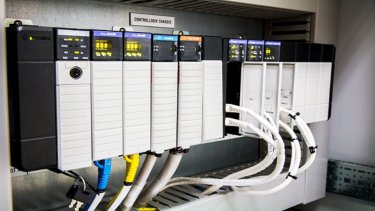
Send Data between Controllers with Handshake in Studio 5000
The Send Data between Controllers with Handshake Sequence is defined shows how to send one packet of buffered data using a Produce / Consume (Class 1) connection over Ethernet/IP.
Tags:
Software
Languages:
English,
Spanish
Deploy Time: 30 Minutes
English
Spanish
Aerospace
Automotive & Tire
Cement
Chemical
Entertainment
Fiber & Textiles
Food & Beverage
Household & Personal Care
Hydrogen
Infrastructure
Life Sciences
Marine
Metals
Mining
Mining, Metals & Cement
Oil & Gas
Power Generation
Print & Publishing
Pulp & Paper
Semiconductor
Water Wastewater
Warehouse & Fulfillment
Airports & Airlines
Mass Transit
Renewable Energy
Manufacturing
Waste Management
Implementer
Software
Industrial Maintenance & Support
SCMSPS - Scalable condition monitoring solution for pumping systems
SCMSPS allows the recording, integration, visualization, and analysis of combined data on a single platform for pumping systems with Drive PF755 and PF755T.
Downloads
Please note: You will need to agree to the Terms & Conditions for each download.
Need Help?
If you need help with an application or have feedback from the Innovation Center, please contact us.
What is this for?
The purpose of this document is to provide guidelines how to setup a load sharing application using a torque follower setup.
Load sharing is a term used to describe a system where multiple drives and motors are coupled and used to run one mechanical load.
The following assumptions are made:
- Drives and motors are properly sized for the application
- The drives are at factory default settings
- The motors are equipped with rugged feedback devices
- Drives are equipped with TLink option module and feedback cards
The example is based on a large diameter bull gear with two motors. The motors are coupled via tooth sprockets and gearboxes.
This creates a rigid connection between the motors, ideal for a torque follower setup.
The torque follower (also known as master-slave) is a type of load sharing setup when we use one master drive in speed regulation and one follower drive in torque regulation.
The torque command generated by the master’s speed loop is transmitted to the follower drive to be used as torque reference.
A torque follower setup makes two or more motors act as 1 big motor. See below torque follower block diagram.
In this example the torque reference is transferred from the master drive to the follower drive via TLink option module.
Is this helpful?
If you are working with systems involving multiple motors coupled to a single load, this document will be very useful to you in setting up an efficient and effective control strategy.
How can I get this working?
- Hardware
- Logix 5580-1756-L8SE Control
- PowerFlex 755T Flux Vector Tuning
- TLink (FO Module) - 20-750-TLINK-FOC-5
- Incremental Encoder Board 20-750-ENC-1
- Software
- Studio5000 (V36)
- Previous knowledge:
- Basic knowledge of Studio5000
- Basic knowledge of PowerFlex 755T.
References documents
- PowerFlex Drives with TotalFORCE control Quick Start, Rockwell Automation Publication 750-QS100D-EN-P - January 2023.
- PowerFlex Drives with TotalFORCE control Programming Manual, Rockwell Automation Publication 750-RM100C-EN-P - August 2022.
- PowerFlex 755T Flux Vector Tuning Application Technique, Rockwell Automation Publication 750-AT006D-EN-P - January 2022.
- TLink Option Module User Manual Original Instructions, Rockwell Automation Publication 750COM-UM100A-EN-P - June 2021.
Installation Guide
Paso 01
Abrir el archivo Project_PF755_PF755T.ACD, reutilizar los Add-On Instructions y UDT (User - Defined Types).
Configure el Drive PF755 ó PF755T utilizando los Add-on Profile y el studio 5000.
Ver video: How to Configure PowerFlex 755TS VFDs with Integrated Motion: Part 2, Online Configuration.
Integración de los Drive PF755_PF755T con Studio 5000_Step1
Paso 02
Abrir el archivo SCMSPS.optix con FactoryTalk Optix Studio.
Ver link: Open a project.
FactoryTalk Optix Studio_Step2
Paso 03
Configure la ruta de comunicaciones del controlador ControlLogix o CompactLogix.
Ver link: Open a project.
FactoryTalk Optix Studio_Ruta de comunicación_Step3
Paso 04
Restaurar la dirección URL de la aplicación FT Analytics GuardianAI.
Web Brower URL_FT GuardianAI_Step4
Paso 05
Crear la aplicación de la FactoryTalk Optix (FTOptixApplication).
Ver link: Export a FactoryTalk Optix Application to a folder.
Exportar una aplicación FactoryTalk Optix a una carpeta_Step5
Paso 06
Al abrir la aplicación que fue creada previamente con FT Optix Studio, se visualizara las siguientes imágenes. (Clica para ampliar)
FTOptixApplication Main View_Step6a
FTOptixApplication Gaurdian AI_Step6b
FTOptixApplication Main View_Step6c
FTOptixApplication Main View_Step6d
FTOptixApplication Main View_Step6e
FTOptixApplication Main View_Step6f
FTOptixApplication Main View_Step6g
Integración de los Drive PF755_PF755T con Studio 5000_Step1
FactoryTalk Optix Studio_Step2
FactoryTalk Optix Studio_Ruta de comunicación_Step3
Web Brower URL_FT GuardianAI_Step4
Exportar una aplicación FactoryTalk Optix a una carpeta_Step5
FTOptixApplication Main View_Step6a
FTOptixApplication Gaurdian AI_Step6b
FTOptixApplication Main View_Step6c
FTOptixApplication Main View_Step6d
FTOptixApplication Main View_Step6e
FTOptixApplication Main View_Step6f
FTOptixApplication Main View_Step6g
SCMSPS - Solución Escalable de Monitoreo de Condición para Sistemas de Bombeo
Versión 1.0 - Marzo de 2025
Step 01
Pasos de configuración VDF
1. General Settings
In this example both drives are equipped with a 20-750-TLINK-FOC-5 (Fiber 5 m) Module located in the Port 4, and a 20-750- ENC-1 Incremental Encoder card in the Port 5.
The following settings apply to both drives.
- 0:65 [Pri Mtr Ctrl Mode] = 4 “Induction FV”. This selects motor control mode as Induction Flux Vector.
- Enter motor data parameters in 10:400 - 10:407.
- 10:1000 [Pri Vel Fb Sel] = 5:4 [Encoder Feeback]. This selects incremental encoder as motor feedback source.
- Enter encoder resolution in 5:2 [Encoder PPR].
2. Master Drive setup
- 10:30 [PsnVelTrq Mode A] = 1 “Velocity Reg”. This selects control mode for velocity regulation.
- Select speed reference source in 10:1800 [Vel Ref A Sel]
- Set the speed limits and ramp rates according to the application.
- 10:1392 [Max Speed Fwd]
- 10:1393 [Max Speed Rev]
- 10:1915 [VRef Accel Time 1]
- 10:1917 [Vref Decel Time 1]
- 10:930 [Direction Mode] = 1 “Bipolar”.This selects the Velocity reference can be positive and negative.
- 10:2020 [LdObs Mode] = 1 “LdObs Only”.
- This is the recommended Load Observer setting for velocity mode applications. For more information about Load Observer feature see PowerFlex 755T Flux Vector Tuning, publicación 750-AT006.
- Set output torque limits according to machine design, drive and motor sizing. In this example +/-150%.
- 10:2083 [Torque Limit Pos] = 150%
- 10:2084 [Torque Limit Neg] = -150%
3. TLink Option Module Master Drive setup
- 4:1 [TLink Mode] = 1 “Mode A”. Master sends 2 words synchronized 50 mµ updates.
- 4:2 [TLink Role] = 0 “Master”. Sets TLink role for the drive, Master sources data to nodes.
- 4:201 [TLink Out Sel 1] = 0 “Trq Ref Out”. Selects the torque reference output.
- 4:202 [TLink Out Sel 2] = 3 “VRef Ramped”. Selects the ramped velocity reference output.
4. Slave Drive setup
- 110:30 [PsnVelTrq Mode A] = 2 “Torque Reg”. This selects control mode for torque regulation.
- 10:2000 [Trq Ref A Sel] = 4:203 [TLink In 1]. This gets Torque Ref from master.
- 10:1800 [VRef A Sel] = 4:206 [TLink In 2]. This gets ramped velocity reference from master.
- 10:2020 [LdObs Mode] = 0 “Disabled”. This is the recommended Load Observer setting for torque mode applications.
- Set output torque limits according to machine design, drive and motor sizing. The slave drive values are set slightly higher as the command values are clamped by the master drive.
- 10:2083 [Torque Limit Pos] = 155
- 10:2084 [Torque Limit Neg] = -155%
5. TLink Option Module Slave Drive setup
- 4:1 [TLink Mode] = 1 “Mode A”. slave receive 2 words synchronized 50 mµ updates.
- 4:2 [TLink Role] = 0 “Slave”. Sets TLink role for the drive, Slave consumes data from the master.
- 4:3 [TLink Status] = 1 “Tx Active”. Verify transmission of data by master (TLink option module in master drive)
- 4:3 [TLink Status] = 3 “In Sync”. Verify that slave drive is synchronized to the master drive in slave (TLink option module in slave drive)
Step 02
Tuning Steps
Tuning is critical working in Flux Vector control mode. We will use the Autotune function to measure motor characteristics. Autotune is composed of several individual tests, each of which is intended to identify one or more motor parameters. These tests require motor nameplate information to be entered into the drive parameters. We can run all the tests in the parameter 10:910 [Autotune].
These are the recommended steps:
1- Enter motor data parameters in 10:400 – 10:407.
2 - Run 10:910 [Autotune] = 1 “Direction”. This allows you to determine if the motor rotates in the desired direction. Also allows you to check if encoder feedback count increases in value for a forward velocity command.
3 - Measure the motor electrical parameters:
- Set 10:510[MtrParam C/U Sel] = 1 “User Entered”
- Run 10:910 [Autotune] = 3 “Rotate MtrID” to measure the motor electrical parameters. It initiates motion and rotates the load. To obtain the most accurate measure of motor flux current, disconnect the load for this test.
- If you cannot initiate motion to rotate the load, then run 10:910 [Autotune] = 2 “Static MtrID” to measure the motor electrical parameters.
4 - Set the current regulator bandwidth 10:445 [VCL CReg BW]
- 125 when 10:425 [PWM Frequency] = 1.33 kHz
- 250 when 10:425 [PWM Frequency] = 2 kHz
- 375 when 10:425 [PWM Frequency] = 4 kHz
5 - Run 10:910 [Autotune] = 4 “InertiaMotor” to measure the motor inertia. This test initiates momentary motor rotation to measure and update 10:900 [Motor Inertia].
This test is only an option if the load can be disconnected to run the test. If the load cannot be disconnected, you should enter the value manually in 10:900 [Motor Inertia].
6 - In the master drive, run 10:910 [Autotune] = 5 “Inertia Total”. This test initiates momentary rotation of the motor and load to measure total inertia and calculate 10:901 [Load Ratio]. After selecting this value, you must issue a start command to begin the test. Perform this test with the load connected to the motor.
10:900 [Motor Inertia] and 10:901 [Load Ratio] are used to calculate the torque scaler Kj, an internal parameter that compensates for the effects of inertia and affects overall tuning. Load Ratio is also used to calculate controller gains.
Since the application will be controlled by 2 load sharing motors, the Load Ratio of the Master drive measured during the test can be divided by 2.
7 - In the master drive, run 10:910 [Autotune] = 6 “BW Calc”. The bandwidth calculation test calculates control loop gains and dynamic limits.
8 - Run the master drive and adjust system bandwidth in 10:906 [System BW] if necessary. Decreasing system bandwidth stabilizes the system and increasing it improves performance. Typically, high gain results in a quicker response time, but excessive gain causes system instability.
For more information about tuning see PowerFlex 755T Flux Vector Tuning, publication 750-AT006.
Step 03
Signal Checks and Operation Steps
1. Signals Checks
Run the master motor (only) up to nominal speed. Master Drive: Check 10:2087 [Trq Ref Limited] during acceleration.
2. Operation
To start the torque follower application
- Start the follower drive first. Since the master drive is not running the follower drive is not receiving any torque reference. At this stage the motor is fluxed and ready to go.
- When the slave drive is running start the master drive. The speed regulator of the master drive generates a torque command which is used in the master drive and transferred to the follower drive. Both drives and motor will take an equal share of the load and act as 1 big one.
To stop the torque follower crusher application
- Stop the master drive first. The master drive will ramp down its speed and send out a negative torque command to the slave drive to assist. The torque command values can be clamped by the bus regulator reducing the amount of regenerative energy.
- Stop the follower drive once the master drive is not active anymore. See Drive status word via the communication interface or via 10:354 [Motor Side Sts 1] bit 1 [Active].
When a drive is faulted
- If the master drive is faulted the follower won’t receive any torque reference. In this condition the slave drive would almost coast to a rest. At this stage there are two options:
- The fault can be cleared, and the master drive can be restarted, the speed will be picked up immediately by the motor encoder (no need for flying start activation).
- The slave drive can be stopped. To make sure the slave drive stops with a controlled deceleration ramp verify that bit 1 [Torq Mode stop] of 10:40 [Motor Cfg Options] is set.
- - If the slave drive is faulted the master drive is taking the full load. It may reach current limit and potentially stall. The drive could then trip on motor overload. The master drive can be stopped.
Step 04
Load Logix program into the controller Steps
1 - On the Studio 5000 development software we open the program “Torque_Follower_with_TLink”, the following image is then displayed, where the controller, an analog and a digital card, as well as the Ethernet card where the PowerFlex 755TS Drives will be part of the network are already added.
2 - On the menu bar, click on “communication” and choose “download” from the options that appear, then click again on the button in the window that opens, as shown in the following image.
3 - We wait for the program to download to the controller
4 - Finally we click on the Yes button on the window that appears after the program is loaded into the controller, this, to change the controller mode to “Remote Run”
Application and Configuration of a Torque Follower System with PowerFlex 755T- and the use of the TLink Module (FO Module)
Version 1.0 - December 2024

SCMSPS - Scalable condition monitoring solution for pumping systems
SCMSPS allows the recording, integration, visualization, and analysis of combined data on a single platform for pumping systems with Drive PF755 and PF755T.
Tags:
Software
Languages:
English,
Spanish
Deploy Time: 120 Minutes
English
Spanish
Portuguese
Aerospace
Automotive & Tire
Cement
Chemical
Entertainment
Fiber & Textiles
Food & Beverage
Household & Personal Care
Hydrogen
Infrastructure
Life Sciences
Marine
Metals
Mining
Mining, Metals & Cement
Oil & Gas
Power Generation
Print & Publishing
Pulp & Paper
Semiconductor
Water Wastewater
Warehouse & Fulfillment
Airports & Airlines
Mass Transit
Renewable Energy
Manufacturing
Waste Management
Implementer
Software
Smart Manufacturing
Safety Solutions
Development of Safe Zone Applications using Laser Scanner
Development of Safe Zone Applications using Laser Scanner meeting Safety Standards requirements such as ISO 13849-1:2008
What is it for?
The purpose of this solution is to support the development of Safe Zone Solutions using Laser Scanner and Safety Control Systems, enabling the compliance of various machines such as Robotic Cells, Conveyors, and mobile machines.
General Features
Sizing of Integrated Safety Solutions adopting current technologies and established concepts focused on applications in discrete manufacturing industries.
Advantages
- Compliance with the main current safety standards
- Use of certified safety solutions
- Solution enables greater production flexibility associated with safety
- Integrated Solution between Process and Safety
Limitations and Disadvantages
- Updated CCW software required
- Laser Scanner Programming Software must be up to date
- This is a standard sizing; installation definitions, input/output capacities, and safety classifications must be determined later
Downloads
Please note: You will need to agree to the Terms & Conditions for each download.
Need Help?
If you need help with an application or have feedback from the Innovation Center, please contact us.
Is this useful for me?
Sizing performed considering a Laser Scanner, Programmable Relay CR30, and direct start drives, which can also be done with Inverters or Servo Drives.
How can I make it work?
- Hardware: Standard computer or notebook and bill of materials.
- Software: CCW Connected Components Workbench and laser scanner programming software.
Installation guide
To implement, please follow the steps below.
Step 01
Connect as shown below:
development-of-safe-zone-applications-using-laser-scanner_Picture3.png
Step 02
Configure the Laser Scanner by opening the software and connecting.
development-of-safe-zone-applications-using-laser-scanner_Picture4.png
development-of-safe-zone-applications-using-laser-scanner_Picture5.png
Step 03
Configure the Laser Scanner according to the process below.
development-of-safe-zone-applications-using-laser-scanner_Picture6.png
development-of-safe-zone-applications-using-laser-scanner_Picture7.png
Step 04
Download the Laser Scanner programming; after completion, the following message will be displayed.
development-of-safe-zone-applications-using-laser-scanner_Picture8.png
Step 05
Open CCW to download the APP.
development-of-safe-zone-applications-using-laser-scanner_Picture9.png
Step 06
Select “Open Existing” and find the application provided as “SafeZoneApp.ccwsln”.
The location where the application is saved is chosen by the user during download.
After selecting the application, click “Open”.
development-of-safe-zone-applications-using-laser-scanner_Picture10.png
development-of-safe-zone-applications-using-laser-scanner_Picture11.png
Step 07
After loading the application, click “Edit Logic” so you can view the application logic.
development-of-safe-zone-applications-using-laser-scanner_Picture12.png
development-of-safe-zone-applications-using-laser-scanner_Picture13.png
Step 08
After verifying the application, just click “Build” to check for any issues. Once verified, the message “Build Succeeded” will appear.
adapting-conveyor-machines-with-muting-applications_Picture14.png
Step 09
After verification, click “Download” and proceed with the application download process.
development-of-safe-zone-applications-using-laser-scanner_Picture15.png
Step 10
Select the relay connected to the system as shown below.
development-of-safe-zone-applications-using-laser-scanner_Picture16.png
Step 11
A confirmation will be requested to finalize the download process.
development-of-safe-zone-applications-using-laser-scanner_Picture17.png
Step 12
After confirmation, you will be notified that the download process is complete.
development-of-safe-zone-applications-using-laser-scanner_Picture18.png
Step 13
You can evaluate your program through Online verification as shown below (illustrative image of the monitoring solution).
development-of-safe-zone-applications-using-laser-scanner_Picture19.png
development-of-safe-zone-applications-using-laser-scanner_Picture3.png
development-of-safe-zone-applications-using-laser-scanner_Picture4.png
development-of-safe-zone-applications-using-laser-scanner_Picture5.png
development-of-safe-zone-applications-using-laser-scanner_Picture6.png
development-of-safe-zone-applications-using-laser-scanner_Picture7.png
development-of-safe-zone-applications-using-laser-scanner_Picture8.png
development-of-safe-zone-applications-using-laser-scanner_Picture9.png
development-of-safe-zone-applications-using-laser-scanner_Picture10.png
development-of-safe-zone-applications-using-laser-scanner_Picture12.png
development-of-safe-zone-applications-using-laser-scanner_Picture13.png
development-of-safe-zone-applications-using-laser-scanner_Picture14.png
development-of-safe-zone-applications-using-laser-scanner_Picture15.png
development-of-safe-zone-applications-using-laser-scanner_Picture16.png
development-of-safe-zone-applications-using-laser-scanner_Picture17.png
development-of-safe-zone-applications-using-laser-scanner_Picture18.png
development-of-safe-zone-applications-using-laser-scanner_Picture19.png
Development of Safe Zone Applications using Laser Scanner
Version 1.0 - November 2025
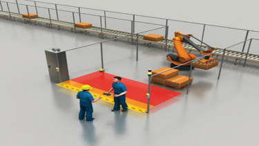
Development of Safe Zone Applications using Laser Scanner
Development of Safe Zone Applications using Laser Scanner meeting Safety Standards requirements such as ISO 13849-1:2008
Tags:
Software
Languages:
English,
Spanish,
Portuguese
Deploy Time: 30 Minutes
English
Spanish
Portuguese
Implementer
Industrial Automation & Control
Micro800 and Kinetix 5100 Practical Setup
The main objective of this application is to provide a startup program for any motion control project involving the Kinetix 5100 and Micro800.
How can I make it work?
Downloads
Please note: You will need to agree to the Terms & Conditions for each download.
Need Help?
If you need help with an application or have feedback from the Innovation Center, please contact us.
What is this for?
The main goal of this application is to provide engineering teams—whether from end users, integrators, OEMs, etc.—with a ready-to-use startup program for any motion control project involving Kinetix 5100, Micro 800, and PanelView 800.
The executable files for running the motion control application were developed using the software environments of Connected Components Workbench (for programming the Micro 800 and PanelView 800) and KNX5100C (for configuring the Kinetix 5100 drive). These files include the necessary program and configuration to control the Micro800, the parameters for the K5100, and the HMI program.
Is this useful for me?
This application was designed with a basic and easily accessible bill of materials, allowing users to execute it with minimal complexity. Additionally, it is fully functional for any industry that requires a simple motion control solution.
All of this provides numerous advantages, such as establishing a common foundation for future projects after understanding and working with this type of application. It also helps reduce development and commissioning time for new applications, benefiting plant control and automation teams, integrators, and OEMs. Moreover, it serves as a practical tool for technical training and concept testing, while enhancing understanding of motion control and related topics.
How can I make it work?Requirements: products, tools, prior knowledge.
Hardware
Software
- Connected Components Workbench (V23 or higher)
- KNX5100C (V 4.0 or higher)
Knowledge
- Basic knowledge of programming and configuration in Connected Components Workbench (CCW) software, as well as experience with programming and using Micro 800, PanelView 800, and Kinetix 5100 using the configuration software KNC5100C.
- Understanding the Micro Control System Environment.
- Architecture Scheme & connections for application use
Manuals / Technical Notes
Inside the folder available for download along with the application files, you will find three manuals that complement the usage and understanding of the various components and devices used in this application. These are:
- CCW: Using project from Sample Code Library
- Connected Components Workbench v21: Implicit messaging UDFBs for Kinetix 5100 and PowerFlex 520-series drives
- Micro830, Micro850, and Micro870 Programmable Controllers
Implementation Guide
Step 1: Download Design and Configuration Software – CCW & KNC5100C
From the Rockwell Automation downloads page, you can search and download each of the mentioned software tools by name.
Once downloaded, install them to have them available for the necessary configuration tasks.
micro800-and-kinetix-5100-practical-setup_Picture4.jpg
Step 2: FT Linx Configuration – Firmware Version Verification
You must verify Ethernet connectivity with the respective devices using FT Linx, ensuring that the firmware versions are up to date.
micro800-and-kinetix-5100-practical-setup_Picture5.jpg
After confirming proper connectivity, it is important to verify that all devices have the latest firmware versions installed.
micro800-and-kinetix-5100-practical-setup_Picture6.jpg
If the firmware is not up to date, it can be updated using the ControlFLASH Plus application, which is automatically installed alongside Connected Components Workbench.
micro800-and-kinetix-5100-practical-setup_Picture7.jpg
Step 3: Drive Configuration in KNX5100C
Open the attached downloadable file K5100_Project_3_OK.prj in the KNX5100C software.
Confirm the assigned USB port for connection.
micro800-and-kinetix-5100-practical-setup_Picture8.jpg
We download the project to the drive.
micro800-and-kinetix-5100-practical-setup_Picture9.jpg
micro800-and-kinetix-5100-practical-setup_Picture10.jpg
Once the previous procedure is completed, the system should be running online and functioning correctly.
Next, proceed to review and confirm the various main program settings required for proper operation, such as assigning the IP address and configuring the communication settings.
micro800-and-kinetix-5100-practical-setup_Picture12.jpg
micro800-and-kinetix-5100-practical-setup_Picture11.jpg
Other Important Settings to Configure:
micro800-and-kinetix-5100-practical-setup_Picture13.jpg
Operation Mode I/O → This setting defines the operation mode, allowing another device to control the drive—in this case, the Micro800.
Motor Selection → By choosing the catalog number option, you must enter the catalog number of the TLP motor proposed in the bill of materials section. Then, confirm the incremental operation method.
micro800-and-kinetix-5100-practical-setup_Picture14.jpg
micro800-and-kinetix-5100-practical-setup_Picture15.jpg
micro800-and-kinetix-5100-practical-setup_Picture16.jpg
General Setting → We can configure rotation direction (1), if we using a braking resistor – we can define its parameters (2). Its available the option to enable the braking option and set the braking time (3), finally, we can configure the zero speed detection – and its notification (4)
micro800-and-kinetix-5100-practical-setup_Picture17.jpg
Digital I/O → Inputs are assigned according to the application requirements. For this case, confirm that the first input is set as “Homing Switch”, and perform the necessary status and functionality tests—mainly to ensure proper connection, as shown in the corresponding image.
Step 4 – CCW Configuration
Initially, it is necessary to confirm in the communications settings that the communication software being used is FT Linx.
micro800-and-kinetix-5100-practical-setup_Picture18.jpg
micro800-and-kinetix-5100-practical-setup_Picture19.jpg
Then, proceed to import the project included in the application’s attached files:
K5100_Class1_UDFBs_with_PV800_Sample_Screens.ccwarc
micro800-and-kinetix-5100-practical-setup_Picture20.jpg
Note: For future use of the project, it is important to save it locally on your PC using: File → Save Project As
The first adjustment must be made in the Micro 870 controller. Right-click on the controller and select Controller Change, then choose the catalog number of the device you are working with in practice (refer to the bill of materials at the beginning of the documentation).
micro800-and-kinetix-5100-practical-setup_Picture21.jpg
After completing this step, go to the Ethernet settings in the controller options and confirm that the IP address is correctly configured according to the criteria defined earlier.
micro800-and-kinetix-5100-practical-setup_Picture22.jpg
Finally, in the Modules section, ensure that the settings match those shown in the reference image. This step confirms that the device connected to the Micro800 via Ethernet is the correct Kinetix 5100 drive, and verifies its IP address, connection status, and module compatibility.
micro800-and-kinetix-5100-practical-setup_Picture23.jpg
Step 5 – Panel View 800 Configuration
micro800-and-kinetix-5100-practical-setup_Picture24.jpg
Just as we began with initial adjustments for the Micro800 configuration, in this case, we will perform the first setup for the PanelView 800, changing the screen type in the project to match the one selected in the previously proposed bill of materials.
micro800-and-kinetix-5100-practical-setup_Picture25.jpg
micro800-and-kinetix-5100-practical-setup_Picture26.jpg
It is important to confirm (and adjust if necessary) the IP address defined earlier, ensure the use of the Ethernet port, and verify that the CIP industrial communication protocol is selected. The remaining settings can be left as default.
This application is designed to work with two screens, The main screen is composed as follows in the next picture:
micro800-and-kinetix-5100-practical-setup_Picture27.jpg
The second screen focuses on graphing trends and servo motor behavior over time. Additionally, the buttons used on this screen are essentially the same as those on the main screen, with their respective functions.
micro800-and-kinetix-5100-practical-setup_Picture28.jpg
Step 6 – Commissioning & Demostration
After completing the previous configurations, everything is ready to download the program to the Micro800 controller and verify the proper operation of the application.
micro800-and-kinetix-5100-practical-setup_Picture29.jpg
micro800-and-kinetix-5100-practical-setup_Picture30.jpg
micro800-and-kinetix-5100-practical-setup_Picture31.jpg
micro800-and-kinetix-5100-practical-setup_Picture32.jpg
You must also download the program to the PanelView 800. This process follows similar steps.
micro800-and-kinetix-5100-practical-setup_Picture33.jpg
micro800-and-kinetix-5100-practical-setup_Picture34.jpg
The following image highlights all the libraries required to program drive control in the Micro800 controller. It is recommended that, if you plan to work on similar new projects, you read and follow the steps outlined in the technical notes/manuals shared in the Links of Interest section:
- Connected Components Workbench v21: Implicit messaging UDFBs for Kinetix 5100 and PowerFlex 520-series drives
- CCW: Using project from Sample Code Library
micro800-and-kinetix-5100-practical-setup_Picture35.jpg
All these libraries are reused in the design of the main program within the project
micro800-and-kinetix-5100-practical-setup_Picture36.jpg
micro800-and-kinetix-5100-practical-setup_Picture37.jpg
The DEVICE OBJECT is the main block of the program. As you progress through the functional block code, you will find the programming for all the buttons shown on the screens and other components of the application.
micro800-and-kinetix-5100-practical-setup_Picture38.jpg
micro800-and-kinetix-5100-practical-setup_Picture39.jpg
For example, the previous images show the programming of the drive ON/OFF button.
Another important manual we recommend reviewing to understand the DEVICE OBJECT configuration (also linked in the Links of Interest) is:
- Micro830, Micro850, and Micro870 Programmable Controllers / Appendix H – User-defined Function Block Motion Instructions
This manual contains the necessary information to configure the block for the Kinetix 5100, including its instructions and descriptions.
micro800-and-kinetix-5100-practical-setup_Picture40.jpg
It is essential to create a DEVICE OBJECT for each drive assigned to the Micro800 controller, especially if the project or application requires working with multiple drives.
We recommend reviewing the full appendix in detail to fully understand how these instruction blocks can be programmed according to the needs and objectives of your applications or projects.
micro800-and-kinetix-5100-practical-setup_Picture41.jpg
With the application running and initial tests confirming proper operation, you can begin by:
- Verifying the connection with the Micro800
- In the DEVICE OBJECT block, checking the Control Status – 7, which indicates readiness to receive instructions
- Confirming that Active = True, meaning the servo motor is “ON” and ready to start
One way to verify the application’s performance is by using the Scope feature in KNX5100C, the drive configuration software.
micro800-and-kinetix-5100-practical-setup_Picture42.jpg
One way to verify the application’s performance is by using the Scope feature in KNX5100C, the drive configuration software.
micro800-and-kinetix-5100-practical-setup_Picture43.jpg
micro800-and-kinetix-5100-practical-setup_Picture44.jpg
You can also change the channels to monitor other variables relevant to your objectives.
By clicking the Run button to start and begin graphing the system’s response, you gain access to multiple options within the Scope function in KNX5100C. This is the key information to understand for your motion control startup application.
A clear example is the data available in the graph: as shown in the previous image, you can place the cursor at any point in time(1) and, using the channel info boxes, identify the values of the selected variables—position and speed—at that specific moment.
You can also observe changes over time. For instance, when speed drops to zero(2), the servo motor’s position remains fixed from that moment onward.
Micro800 and Kinetix 5100 Practical Setup
Version 1.2 - May 2026

Micro800 and Kinetix 5100 Practical Setup
The main objective of this application is to provide a startup program for any motion control project involving the Kinetix 5100 and Micro800.
Languages:
English,
Spanish,
Portuguese
Deploy Time: 60 Minutes
Portuguese
English
Spanish
Aerospace
Airports & Airlines
Automotive & Tire
Cement
Chemical
Entertainment
Fiber & Textiles
Food & Beverage
Household & Personal Care
Hydrogen
Infrastructure
Life Sciences
Marine
Metals
Mining
Mining, Metals & Cement
Oil & Gas
Power Generation
Print & Publishing
Pulp & Paper
Semiconductor
Water Wastewater
Warehouse & Fulfillment
Mass Transit
Renewable Energy
Manufacturing
Waste Management
Implementer
Software
Safety Solutions
Smart Manufacturing
Adapting Conveyor Machines with Muting Applications
Adapting Conveyor Machines with Muting Applications with Programmable Safety Relays and Photoelectric Sensors
What isthis for?
Light curtains are used to detect attempts to access a hazardous area. Under normal operation, if the light curtain detects an object, it causes the safety system to stop any dangerous movement in that area. In some applications, it is desirable for a product to pass through the light curtain without stopping the hazardous movement. This configuration can be achieved through the use of muting.
General Features
This safety function application technique explains how to connect and configure an L-type muting system with two sensors, for one-way passage, including an override (manual override) function and an additional emergency stop (E-stop) button. The system is based on the Guardmaster® 440C-CR30 configurable safety relay.
Downloads
Please note: You will need to agree to the Terms & Conditions for each download.
Need Help?
If you need help with an application or have feedback from the Innovation Center, please contact us.
Advantages
- Compliance with the main applicable safety standards
- Use of certified safety solutions
- Solution that allows for future expansions
- Possibility of integration with control systems via the EtherNet/IP network
Limitations and disadvantages
- The CCW software must be updated to the latest version
- This solution is part of the machine compliance process; the complete compliance process must be carried out
Is this useful to me?
Application already configured with the complete monitoring system for the emergency stop function using configurable safety relays.
How can I make it work?
- Hardware: Notebook and Bill of Materials.
- Software: CCW Connected Components Workbench
Solution Layout:
adapting-conveyor-machines-with-muting-applications_Picture3.png
Implementation Guide
Open the CCW software; once opened, it will display a screen similar to the one shown below:
adapting-conveyor-machines-with-muting-applications_Picture4.png
Select “Open Existing” and browse for the application provided as “Safety-at163.ccwsln”. The location where the application is saved is defined by the user at the time of download. After selecting the application, click “Open”.
adapting-conveyor-machines-with-muting-applications_Picture5.png
adapting-conveyor-machines-with-muting-applications_Picture6.png
Once the application is loaded, click “Edit Logic” to view the application logic; adjust the outputs as shown below.
adapting-conveyor-machines-with-muting-applications_Picture7.png
adapting-conveyor-machines-with-muting-applications_Picture8.png
adapting-conveyor-machines-with-muting-applications_Picture9.png
Once the application has been verified, simply click “Build” to check for any issues; if validation is successful, the message “Build Succeeded” will be displayed.
adapting-conveyor-machines-with-muting-applications_Picture10.png
After verification, click “Download” and proceed with the application download process.
adapting-conveyor-machines-with-muting-applications_Picture11.png
Select the relay connected to the system as shown in the image below:
adapting-conveyor-machines-with-muting-applications_Picture12.png
You will be prompted to confirm the completion of the download process.
adapting-conveyor-machines-with-muting-applications_Picture13.png
After confirmation, the system will indicate that the download process has been successfully completed.
adapting-conveyor-machines-with-muting-applications_Picture14.png
You can evaluate your program through Online verification, as shown in the image below (illustrative image of the monitoring solution).
adapting-conveyor-machines-with-muting-applications_Picture15.png
adapting-conveyor-machines-with-muting-applications_Picture4.png
adapting-conveyor-machines-with-muting-applications_Picture5.png
adapting-conveyor-machines-with-muting-applications_Picture6.png
adapting-conveyor-machines-with-muting-applications_Picture7.png
adapting-conveyor-machines-with-muting-applications_Picture8.png
adapting-conveyor-machines-with-muting-applications_Picture9.png
adapting-conveyor-machines-with-muting-applications_Picture10.png
adapting-conveyor-machines-with-muting-applications_Picture11.png
adapting-conveyor-machines-with-muting-applications_Picture12.png
adapting-conveyor-machines-with-muting-applications_Picture13.png
adapting-conveyor-machines-with-muting-applications_Picture14.png
adapting-conveyor-machines-with-muting-applications_Picture15.png
Adaptation of Conveyor Machines with Muting Applications
Version 1.2 - May 2026
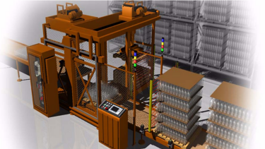
Adapting Conveyor Machines with Muting Applications
Adapting Conveyor Machines with Muting Applications with Programmable Safety Relays and Photoelectric Sensors
Tags:
Software
Languages:
Portuguese,
English,
Spanish
Deploy Time: 45 Minutes
English
Spanish
Chemical
Implementer
Software
Process Solutions
Temperature Model in Reactors
Reactors in many industries are key equipment for transforming raw materials into intermediate products or final products and need temperature controls.
What does this application do?
Context: Reactors in many industries are key equipment for transforming raw materials into intermediate products or final products. To achieve this transformation, in some cases temperature control is required to guarantee the operating temperature.
Objective: Use temperature control to guarantee the operation of the performance of chemical reactions.
How to use:
1 - The reactor volume 1.1 [m³]
2 - First order reaction with respect to the concentration of propylene oxide and zero order with respect to excess water, reaction model is followed.
3 - Representation of the reaction.
4 - The activation energy is
Downloads
Please note: You will need to agree to the Terms & Conditions for each download.
Need Help?
If you need help with an application or have feedback from the Innovation Center, please contact us.
5 - The units are
6 - Conversion of reaction is assumed to be 85%
7 - Initial Flow,
Limitations:
In the current configuration, the chosen reactor is an ideal perfect mixture reactor (ideal CSTR) so that in the liquid inside, it is assumed that:
- In the reactor there is no evaporation of any of the components and, additionally, the adiabatic process is considered.
- Mixture properties are not considered, that is, the properties of the mixture will be the weighted sum of the properties of each of the species.
- The properties of substances are all independent of composition and, therefore, invariant over time.
- Although the reaction is reversible, the reverse reaction can be considered negligible.
Problem to be addressed: The idea is to have an initial configuration element, in which temperature is an important parameter to produce Propylene Glycol.
Is this application relevant to me?
The temperature and reaction control model is useful because it can be used by other developers to represent the reaction model that is influenced by temperature.
How can I make it work?
Requirements: products, tools, prior knowledge.
Software:
- Studio5000 34.11.00
- FactoryTalk Logix Echo V3.00.00
- Process Library 5.20.01
Tools: PlantPAX Process Libraries.
Prior knowledge
- Reaction and heat transfer model.
Related Resources and Links
- An efficient two-phase reaction of ethyl acetate production in modified ZSM-5 zeolites - ScienceDirect
- Multi Product Selector
Implementation Guide
Open FactoryTalk Logix Echo, add a new controller and connect it.
temperature-model-in-reactors_Paso01
Download the .ACD setup to your desktop and run it from Studio 5000.
Determining the volume of the reactor is super important, because it gives us key parameters such as the time the reaction will last, which is why we created a label called Reactor Volume, which has a fixed value of 1.1 m3 and coincides with the established assumptions, above.
temperature-model-in-reactors_Paso03
As in all reactions, the appropriate stoichiometry between reactants is important and considering that one of its components is propylene oxide, the tag associated with Propylene Oxide, reagent A, is created.
Which was explained in the assumptions and determined that the Propylene Oxide has an average flow of 10m3/h and this value is established as its input flow.
temperature-model-in-reactors_Paso04
As mentioned in the previous step, it is important to be able to estimate the water flow rate, which would be 6.5 m³/h, corresponding to Reagent B, as previously explained.
Let us recall that this water stream contains traces of H₂SO₄ as a catalyst.
The reaction has propylene oxide and water as reactants in units of [m³/h], initially propylene oxide has 10 [m³/h] and water 6.5 [ m³/h].
The reaction takes place in a reactor of 1.1 [ m³] and with an activation energy of
temperature-model-in-reactors_Paso05
At this point we need the activation energy configuration, for this we will assign a single page in the configuration, there we will enter the different constants in their order.
temperature-model-in-reactors_Paso06
- Activation Constant:
- Ideal Gas Constant:
After the reaction starts, the formation of products such as propylene glycol uses the interaction between reactor volume V, activation energy, propylene oxide compositions A, and this mathematical model is followed.
The production of propylene glycol is given in the following units in
As shown below.
Part B
temperature-model-in-reactors_Paso07-2
Part A
temperature-model-in-reactors_Paso07-1.png
After the reaction starts, the temperature inside the reactor uses the interaction between the initial reactor temperature, the formation energy, and the temperature constant to determine the temperature inside the reactor.
temperature-model-in-reactors_Paso08
temperature-model-in-reactors_Paso01
temperature-model-in-reactors_Paso03
temperature-model-in-reactors_Paso04
temperature-model-in-reactors_Paso05
temperature-model-in-reactors_Paso06
temperature-model-in-reactors_Paso07-1
temperature-model-in-reactors_Paso07-2
temperature-model-in-reactors_Paso08
Temperature Model in Reactors
Version 2.1 - August 2026

Temperature Model in Reactors
Reactors in many industries are key equipment for transforming raw materials into intermediate products or final products and need temperature controls.
Tags:
Software
Languages:
English,
Spanish
Deploy Time: 60 Minutes
Spanish
English
Automotive & Tire
Cement
Chemical
Entertainment
Fiber & Textiles
Food & Beverage
Household & Personal Care
Hydrogen
Infrastructure
Life Sciences
Marine
Metals
Mining
Mining, Metals & Cement
Oil & Gas
Power Generation
Print & Publishing
Pulp & Paper
Semiconductor
Water Wastewater
Warehouse & Fulfillment
Implementer
Software
Industrial Automation & Control
AC Motor AOI Simulator for E300
An AOI to simulate the motor with a E300 to use it in applications where they have to see their behavior and show the visualization applications with data.
How can I make it work?
Downloads
Please note: You will need to agree to the Terms & Conditions for each download.
Need Help?
If you need help with an application or have feedback from the Innovation Center, please contact us.
What does this application do?
An AOI to simulate the motor with a E300 to use it in applications where they have to see their behavior and show the visualization applications with data.
Is this application relevant to me?
Better simulate my operation and motivate the HMI application in a more realistic way.
How can I make it work?Requirements: products, tools, prior knowledge.
Software:
- Studio 5000 library import tools (Devices, UDT, AOI).
Prior Knowledge
- Studio 5000 Logix Designer
- Add-On Instructions (AOI)
- User-Defined Data Types (UDT)
- EtherNet/IP Configuration
- Basic E300 Concepts
Implementation Guide
Create a Studio 5000 Logix Controller File.
Create-Studio-5000-Logix-Program.mp4
Add an Ethernet card to the ControlLogix project.
Add-Ethernet-Card.mp4
Import E300 in the Ethernet Channel created in Step 2.
Import-E300-Module.mp4
Import UDT for E300.
Import-Motor-Data-UDT.mp4
Import AOI for E300.
Add-AOI-for-E300.mp4
Use the AOI in your program.
Use-AOI-in-your-program.mp4
Download the program to the controller.
Download-the-program.mp4
Test the program.
Test-Program.mp4
AC Motor AOI Simulator for E300
Version 2.0 - May 2026
AC Motor AOI Simulator for E300
An AOI to simulate the motor with a E300 to use it in applications where they have to see their behavior and show the visualization applications with data.
Tags:
Software
Languages:
Spanish,
English
Deploy Time: 30 Minutes
Spanish
English
Portuguese
Aerospace
Airports & Airlines
Automotive & Tire
Cement
Chemical
Entertainment
Fiber & Textiles
Food & Beverage
Household & Personal Care
Hydrogen
Infrastructure
Life Sciences
Marine
Metals
Mining
Mining, Metals & Cement
Oil & Gas
Power Generation
Print & Publishing
Pulp & Paper
Semiconductor
Water Wastewater
Warehouse & Fulfillment
Mass Transit
Renewable Energy
Manufacturing
Waste Management
Implementer
Software
Software Evolution
Machine Management and OEE Optimization with Optix and PackML
OEE monitoring and management of industrial machines with FactoryTalk Optix and PackML, generating reports and improving operational efficiency.
How can I make it work?
Downloads
Please note: You will need to agree to the Terms & Conditions for each download.
Need Help?
If you need help with an application or have feedback from the Innovation Center, please contact us.
What does this application do?
The main purpose of the application developed in FactoryTalk Optix software is OEE monitoring and efficient management of industrial machines. The solution is supported by the standardization of PackML, an industry standard that facilitates the communication and operation of automated machines, regardless of their manufacturer. By integrating PackML standardization with the advanced visualization capabilities of Optix, a cutting-edge platform is provided to optimize operations in modern industrial plants.
Features FactoryTalk Optix stands out for its ability to connect to a wide variety of industrial devices and protocols such as OPC UA, Ethernet/IP, Profinet, Modbus, HTTPS, MQTT among others, allowing the integration and real-time monitoring of equipment from different manufacturers from a single IoT platform. In addition, Optix has the ability to create data logs and save that information in a SQL database. This allows historical alarm trends to be presented and PDF reports to be created as needed.
PackML, which defines 17 standardized operating states, ensures consistent machine behavior, facilitating integration into plants using PackML and ISA-TR88.00.02. In addition, the use of predefined Rockwell Automation libraries, such as those for machine safety, speeds up integration and reduces the engineering effort required.
Advantages
- Standardization of states and modes of operation
- Consistency in machine integration
- Flexibility in connectivity
- Impact on development time
- OEE optimization and continuous improvement
- Cost reduction
- Operational efficiency
- Flexibility and scalability
- Improved data quality
- Root cause analysis
- Real-time monitoring
Is this application relevant to me?
Using PackML allows you to obtain detailed data on machine performance in real time. Metrics that affect OEE, such as availability, performance and quality, can be easily monitored and analyzed thanks to PackML’s standardized data structure and Optix’s visualization capabilities.
For OEMs, the use of PackML and ISA-TR88.00.02, together with the advanced capabilities of FactoryTalk Optix, represents a flexible and standard solution that can be offered to different customers. By creating adaptable and reusable solutions, OEMs can reduce development times, increase the robustness of their software, and deliver a consistent user experience.
In addition, standardization allows OEMs to focus on innovation rather than reinventing basic control solutions for each customer. This not only increases the value of their products, but also reduces training and support costs.
How can I make it work?Requirements: products, tools, prior knowledge.
Software:
- Compact Logix 5069-L3100ERMS2 (V36)
Software:
- FactoryTalk Optix (V1.4.2.3)
- Studio5000 (V36)
Prior Knowledge
- Basic knowledge of the FactoryTalk Optix and Studio5000 development environment.
Implementation Guide
Identify the applications and architecture to be used: Studio5000 and FactoryTalk Optix.
2.1 - Open the Studio5000 application and run the OEE_SmartMachine.ACD project and configure the IP addresses to match those of the controller.
Paso2-Imagen1
Paso2-Imagen2
2.2 - Configure the project in Run Mode.
Paso2-Imagen3
Paso2-Imagen4
3.1 - Open FactoryTalk Optix with the HMIOptixStandard1 file.
Paso3-Imagen1
3.2 - Configure communication with the device, entering the IP address of the project controller.
Paso3-Imagen2
Paso3-Imagen3
3.3 - Configure the project tags and the application is now ready for use.
Paso3-Imagen4
Paso3-Imagen5
There is a main monitoring tab where the motor current can be observed. The control buttons follow the color and design standards defined by the ISA-101 standard which focuses on the design of human-machine interfaces for process automation systems. These controls ensure that the design is intuitive and consistent with best practices in the industry.
The interface shows the production of packages per minute, providing visual information on the performance of the system. It also shows the effectiveness, which indicates the percentage of good pieces in the packages produced.
Paso4-Imagen1
The following screens display the OEE KPIs in a visual and accessible manner, focusing on 1-hour, 6-hour, and 12-hour time periods. In these visualizations, OEE is broken down based on production and part loss. Additionally, a bar chart is used to see how OEE varies over specific time intervals.
- In 1-hour, OEE is calculated and displayed every 5 minutes, giving process people the information they need to make quick and efficient decisions.
- In 6-hour, information is updated every half-hour for a broader perspective.
- In 12-hour, information can be viewed every hour.
This provides users with a detailed view of efficiency, quality, and availability, making it easier to identify opportunities for improvement and optimization in production.
Paso5-Imagen1
Paso5-Imagen2
Paso5-Imagen3
This screen performs a historical query of the data that is being stored in a SQL database. The data is queried from the database, where it is stored continuously every five seconds, allowing a detailed analysis of the machine's performance and behaviour in short time intervals. The screen interface includes a DataGrid, which allows the user to view all the stored information in a clear and organized manner.
Paso6-Imagen1
Finally, the 17 standardized operating states are displayed, showing information about the machine when it was stopped, such as how long it was stopped, its execution time, and more. This can be implemented through libraries predesigned by Rockwell Automation.
For example, there is the Machine Builder library from Rockwell Automation, which is a predesigned set of components and templates designed to simplify and accelerate the development of machine applications using Rockwell software platforms, such as Studio5000. It includes reusable code for common machine functions, such as motion control, safety, diagnostics, and more.
Paso7-Imagen1
Paso2-Imagen1
Paso2-Imagen2
Paso2-Imagen3
Paso2-Imagen4
Paso7-Imagen1
Paso3-Imagen1
Paso3-Imagen2
Paso3-Imagen3
Paso3-Imagen4
Paso3-Imagen5
Paso4-Imagen1
Paso5-Imagen1
Paso5-Imagen2
Paso4-Imagen1
Paso6-Imagen1
Machine Management and OEE Optimization with Optix and PackML
Version 2.0 - August 2026

Machine Management and OEE Optimization with Optix and PackML
OEE monitoring and management of industrial machines with FactoryTalk Optix and PackML, generating reports and improving operational efficiency.
Tags:
Software
Languages:
Spanish,
English,
Portuguese
Deploy Time: 45 Minutes
English
Spanish
Food & Beverage
Implementer
Software
Machine & Equipment Builders
Kinetix Premier Integration
The step-by-step process to Premier integration between Kinetix drives and Logix controllers in one platform, simplifying motion setup, diagnostics, and replacements for peak efficiency.
What does this application do?
Premier integration from Rockwell Automation enhances motion control by enabling Kinetix drives and Logix controllers to work natively within an integrated design environment. Using a single software to configure both simplifies axis programming, synchronization, and motion profile management, while configurations are automatically stored in the controller.
This integration provides advanced diagnostics for predictive maintenance, improved visualization through pre-engineered graphics, and automatic device configuration, reducing downtime by restoring firmware and parameters after replacements. The result: an optimized motion solution that boosts efficiency, reliability, and customer productivity.
Is this application relevant to me?
This is useful because Premier Integration between Kinetix drives and Logix controllers delivers key benefits for motion control applications:
- Simplified design and programming: A single software to configure controllers and drives reduces time and errors.
- Precise synchronization and profile management: Ideal for multi-axis systems and complex applications.
- Advanced diagnostics and predictive maintenance: Detect issues before failures occur, preventing unplanned downtime.
- Enhanced visualization: Pre-engineered graphics make operation and monitoring easier.
- Automatic device configuration: Minimizes downtime when replacing drives by restoring firmware and parameters without manual intervention.
Application areas - Food, Manufacturing, Beverage
Download
Please note: You will need to agree to the Terms & Conditions for each download.
Need Help?
If you need help with an application or have feedback from the Innovation Center, please contact us.
How can I make it work?
Requirements: products, tools, prior knowledge.
Hardware
- Personal computer
Software
- FactoryTalk Optix
- Studio 5000
- FT Echo
Prior Knowledge
- Knowledge of programming and configuration in FT Optix and Studio 5000.
Implementation Guide
This document is divided into two parts, two configurations are needed. One for FT Optix and the Studio 5000 configuration.
First we will configure Studio 5000.
Part I.
Use Rockwell Automation Device Libraries in Studio 5000 Logix Designer
Prerequisites
- Basic knowledge of Studio 5000 Logix Designer.
- An existing project already created.
- (Recommended) Studio 5000 Application Code Manager (ACM) installed to speed up the configuration process.
1. Download the Device Libraries
- Go to the Rockwell Automation Download Center: rockwellautomation.com.
- Search for “Device Library” and download the required libraries.
- (Optional) Download Studio 5000 Application Code Manager (ACM) if you haven’t already.
- This free software simplifies and accelerates device library configuration.
- It acts as an extension of Logix Designer for bulk project configuration.
2. Register the Library in Application Code Manager (ACM)
- Locate the setup command file in the root folder of the library.
- Run the script to automatically register all library objects in ACM.
- Once the script is completed, close the window.
3. Import Library Objects Using the Import Library Objects Plugin
In your Logix Designer project, right-click on any Task.
Select Plugins → Import Library Objects.
The Library Object Import Wizard will open this is a lightweight version of ACM inside Logix Designer.
On the left panel, you’ll see your list of registered libraries (those for which you ran the setup script).
Inside ralib device folder, you’ll find all Rockwell Automation device library objects.
Common folders include power discrete devices, network devices, etc.
For example, open the Power Motion folder and drag Kinetix 5500 device into the right panel under Library Objects.
You can drag multiple devices or instances if you wish to configure them in one import process.
kinetix-primer-integration_Imagen 1
4. Configure Object Parameters
In the Object Configuration window, fill out the object parameters:
- Name → The instance name for the AOI.
- Description → A short helpful text that appears in the AOI description field and HMI faceplates.
Use the dropdowns to select the Task and Program where the routine will be imported.
Under Tag Scope, choose whether to create Program Scope or Controller Scope tags.
For some power device objects, configure Object Interface Data Type:
If using a PlantPAx system with a P controller, select Predefined Data Type and Controller Scope tags.
Set Include Hardware as needed:
- True → The wizard automatically creates and configures the device module in the IO Tree.
- False → If you already have the module, make sure it matches the required definition in the Device Library Reference Manual.
Verify the generated Module Name do not use the same name as the AOI.
kinetix-primer-integration_Imagen 2
5. Complete the Import Wizard
In the Linked Libraries tab, click Auto Create to generate all required components.
Click Next to review pending changes.
Unless specific modifications are required, proceed to Finish.
Once the import completes: The module appears in the IO Configuration Tree.
A new routine is created with a rung containing the AOI instance and all required tags.
The code should compile without errors — no manual programming needed.
kinetix-primer-integration_Imagen 3
6. Integrate Custom Logic
Device AOIs include interface tags used to connect your own control logic:
- CMD (Command) → Used to control device outputs (e.g., Start, Jog, Locate LED).
- STS (Status) → Provides status feedback (faults, warnings, connection, etc.).
- SET (Settings) → Used for configurable parameters (e.g., Speed Setpoint, Trip Setpoint).
- INF (Information) → Transfers data between related objects (e.g., between Power Device and Extension, or Safety Device and Group).
Do not write directly to module output tags that are already linked to an AOI.
When using PlantPAx or MachineBuilder instructions, they will automatically write to these control interfaces.
kinetix-primer-integration_Imagen 1
kinetix-primer-integration_Imagen 2
kinetix-primer-integration_Imagen 3
factorytalk-optix-condition-monitoring-dashboards_16x9-optix_monitoreo_step1_image17.jpg
Part II.
Use Device Libraries with FactoryTalk Optix
Prerequisites
- FactoryTalk Optix Studio v1.4 or later installed.
- Rockwell Automation libraries downloaded from the Product Compatibility and Download Center (PCDC).
1. Download and Install the Device Library
Go to Rockwell Automation’s PCDC website.
Search for the FactoryTalk Optix Library and verify version compatibility.
Download the latest release package.
Run the provided setup script to automatically copy library files to the default user library location.
The script prepares content for both FactoryTalk Optix Studio and Studio 5000 Application Code Manager.
2. Import Library Objects into the Project
Open FactoryTalk Optix Studio and create or open a project.
For a new project: Enter a project name. Choose the display size. Click Create.
Organize your structure:
- In the UI folder, right-click → Add Subfolder.
- Rename it to match the library name using the edit icon.
- Open the Libraries Window using the toolbar icon.
The window lists all available libraries from the default path (including those installed earlier).
Select the new library to filter its components.
Drag-and-drop the desired library component into your new subfolder.
The folder now contains:
- Device faceplates
- Graphic symbols
- Private elements (panels, widgets)
- Help panels
If you need multiple device objects and a “Conflicting Types Detected” dialog appears, choose:
- Skip All → to keep existing types.
- Replace All → to update to a newer version.
- Rename All → to create alternate type names.
kinetix-primer-integration_Imagen 4
3. Copy and Configure the Style Sheet
In the UI folder, add a new subfolder named Style Sheets.
Re-open the Libraries Window and select the Style Sheets Library.
Drag the ISA Style Sheet into your new Style Sheets folder.
This style sheet follows ISA-101 HMI standards and is recommended for consistent visualization. Close the Libraries Window.
Under the UI folder, select Native Presentation Engine.
In its Properties, set Style Sheet = ISA Style Sheet.
kinetix-primer-integration_Imagen 5
4. Configure the Communication Driver and Import Tags
If no station exists yet, open the Dashboard → Configure Communications to Devices.
- Click New Station.
- Choose RAE EtherNet/IP Station → Next.
- Enter the Controller Path and IP Address in the Root Property.
- Confirm with Next → the new station appears under Available Devices.
- Select the Configured Station in the Communication Drivers folder.
In its properties:
- Set Enable Extended Properties = True.
- Toggle Online Mode for tag import.
- The Tag Import process starts automatically.
- Review all detected controller tags.
- Select All or only required tags → Next.
When import completes, the device appears with synchronized tag data.
Click Exit to close the wizard.
kinetix-primer-integration_Imagen 6
5. Configure Graphic Symbols
In your UI folder, right-click the target window or screen → New → [Library Folder] → [Device].
Under Graphic Symbols, choose the desired representation: Text Button or Graphic Button.
Link the symbol to its Add-On Instruction (AOI) instance: Select the button → set Reference Tag by browsing to the device object tag.
For Configuration Label:
Leave blank to auto-populate from tag description metadata, or Enter a custom string. Keep all other parameters as default.
kinetix-primer-integration_Imagen 7
6. Save the Project and Create Runtime
When ready to test, click the Emulator drop-down → Local.
Press + to add a New Target Device.
Fill in:
- Target Name
- IP Address
Destination Path of the target Optix Panel
Run the emulation.
kinetix-primer-integration_Image 8
kinetix-primer-integration_Imagen 4
kinetix-primer-integration_Imagen 5
kinetix-primer-integration_Imagen 6
kinetix-primer-integration_Imagen 7
kinetix-primer-integration_Image 8
Kinetix Premier Integration
Version 1.2 - June 2026
Kinetix Premier Integration
The step-by-step process to Premier integration between Kinetix drives and Logix controllers in one platform, simplifying motion setup, diagnostics, and replacements for peak efficiency.
Tags:
Software
Languages:
English,
Spanish
Deploy Time: 60 Minutes
OEM
System Integrator
English
Portuguese
Spanish
Aerospace
Automotive & Tire
Cement
Chemical
Entertainment
Fiber & Textiles
Food & Beverage
Household & Personal Care
Hydrogen
Infrastructure
Life Sciences
Marine
Metals
Mining
Mining, Metals & Cement
Oil & Gas
Power Generation
Print & Publishing
Pulp & Paper
Semiconductor
Water Wastewater
Warehouse & Fulfillment
Implementer
Hardware
Digital Transformation
Easy Dashboards and Control for a Powerflex 520
This is a Connected Component Workbench development that provides basic parameters monitoring and control, either from a PanelView 800 or remotely (through VNC)
Easy Dashboards and Control for a Powerflex 520 enables you to have a ready to use code and HMI screens to apply them with PowerFlex 523 and PowerFlex 525 drives. This is a Connected Component Workbench development that provides basic parameters monitoring and control, either from a PanelView 800 or remotely (through VNC).
Target to use with PowerFlex 523 and 525 component drives from Rockwell Automation.
This code can be used with the following equipment:
- PowerFlex 523
- PowerFlex 525
- Micro850
- Micro870
- PanelView 800
What does this application do?
The main purpose is to provide visualization and basic control through principal parameters as a ready-to-use development for basic drive control. In addition, it will be possible to access the information contained in the dashboards remotely (Internet).
This can be applied to control systems that include Micro-controllers and Powerflex 520 component drives. Implicit and explicit messaging are used (the most important parameters are handled by implicit messaging).
General Features
- Basic Control parameters modification:
- Reference Speed
- Acceleration Time
- Deacceleration Time
- Position Reference
- Drives faults reset
- Visualization of the following parameters:
- Ready
- Active
- Command Speed
- Actual Speed
- Drives fault
- Output current
- Output voltage
- DC Bus voltage
- Drive temperature
- Consumed energy
- Elapsed power
- Accumulated cost savings
- Remote access to the PanelView 800 screens through FTP functionalities
Limitations/Disadvantages
- Limited to PowerFlex 523 and 525
- Limited to Micro800 and PanelView 800
- Parameters selected are fixed
Download
Please note: You will need to agree to the Terms & Conditions for each download.
Need Help?
If you need help with an application or have feedback from the Innovation Center, please contact us.
How can I make it work?
Requirements: products, tools, prior knowledge.
Hardware
- PowerFlex 523, PowerFlex 525
- Micro 850, Micro 870
- PanelView 800
Software
- Connected Component Workbench, version 21 or higher.
- The firmware of the equipment used must be compatible with the version of Connected Component Workbench.
- User-defined Function Blocks:
- RA_PF523_VEL
- RA_PF525_VEL
- RA_PF525_POS
- RA_PFx_ENET_PAR_READ
- RA_PFx_ENET_PAR_WRITE
Background knowledge
- Basic knowledge of programing and configuration in Connected Component Workbench software:
- PowerFlex 523/525 and PanelView 800 configuration.
- Ladder Language.
Implementation Guide
Communication Settings.
Configure VNC settings in PanelView 800.
Go to the main configuration screen.
Press terminal settings.
Press Communication.
Press VNC Settings.
Parameters import.
Import “Parameters_52X”.
PanelView800 configuration.
Verify that all FTP Accessibility Settings are enable.
Configuration of email server and account setting to send email on PV800 (optional).
Configuration of the PowerFlex 523/525.
Create the PowerFlex as Ethernet modules (this enables implicit messaging)
PowerFlex523 communicated with EIP card (2 ports) and speed control mode.
PowerFlex525 communicated by ethernet Embedded IP and position control mode.
Configuration of parameters for Ethernet communication. For communication by 25-COMM-E2P card.
Configuration of parameters for Ethernet communication. For the communication of the PF525 through the embedded EIP port.
Parameter setting for control mode: Speed.
Parameter setting for control mode: Position.
Compile the Micro800 program.
Validate PV800 application.
Verify the right connection and IP assignment of the equipment in the Ethernet IP network.
Download program (without errors) to Micro800 controller and leave in run mode.
Download the HMI application to the PV800 and execute it.
Program download and commissioning.
Compile the Micro800 program.
Validate PV800 application.
Verify the right connection and IP assignment of the equipment in the Ethernet IP network.
Download program (without errors) to Micro800 controller and leave in run mode.
Download the HMI application to the PV800 and execute it.
Easy Dashboards and Control for a Powerflex 520
Version 1.2 - July 2026
Easy Dashboards and Control for a Powerflex 520
This is a Connected Component Workbench development that provides basic parameters monitoring and control, either from a PanelView 800 or remotely (through VNC)
Tags:
Hardware
Languages:
English,
Portuguese,
Spanish
Deploy Time: 60 Minutes
English
Spanish
Portuguese
Aerospace
Airports & Airlines
Automotive & Tire
Cement
Chemical
Entertainment
Fiber & Textiles
Food & Beverage
Household & Personal Care
Hydrogen
Infrastructure
Life Sciences
Marine
Metals
Mining
Mining, Metals & Cement
Oil & Gas
Power Generation
Print & Publishing
Pulp & Paper
Semiconductor
Water Wastewater
Warehouse & Fulfillment
Mass Transit
Renewable Energy
Manufacturing
Waste Management
Implementer
Hardware
Consulting & Integration Services
PowerFlex 755 Drive Control with FactoryTalk Optix
Application for PowerFlex 755 Drive control and monitoring in applications where there is no controller, but a computer or OptixPanel can be used.
What does this application do?
This application, based on the new supervisory system called FactoryTalk Optix, allows us to control a motor through a PowerFlex 755 Variable Frequency Drive using EtherNet/IP communication. Currently, the connection is not direct between the two products; instead, we use a virtual Controller called FactoryTalk Logix Echo, which resides on the same computer or Windows-based OptixPanel that contains the FactoryTalk Optix application.
Is this application relevant to me?
This development is useful in remote applications where we do not have a process controller, but we leverage the Drive's DeviceLogix to control the process through its analog and digital inputs, and we use FactoryTalk Logix Echo for Ethernet communication between the Drive and the FactoryTalk Optix supervisory system.
Download
Please note: You will need to agree to the Terms & Conditions for each download.
Need Help?
If you need help with an application or have feedback from the Innovation Center, please contact us.
How can I make it work?
Requirements: products, tools, prior knowledge.
Hardware
- PowerFlex 755 or PowerFlex 755T
Software
- Connected Components Workbench™ (21.00 or higher)
- FactoryTalk Logix Echo (3.00.00)
- Studio 5000 (35.13.00)
- RSLinx Classic (4.31.00)
- FactoryTalk Optix (1.3.3.3)
Prior Knowledge
- Basic knowledge of programming and configuration in Connected Components Workbench™, FactoryTalk Logix Echo, FactoryTalk Optix software and knowledge of the functionality and parameterization of PowerFlex 755 drives.
Implementation Guide
Download the file: FTOptix_PF755.ccwarc, open the CCW application, click File, Import Project, and import the project.
Powerflex 755 Drive Control with FactoryTalk Optix Step1_Image1
Explore the program, click on PowerFlex755_1, Parameters, Port 13, and verify the Drive’s IP address; for this case, we use 192.168.1.20.
In this application, the Drive can act as a controller by applying the Rockwell product feature called PREMIER INTEGRATION. An EtherNet cable will be used to communicate between the PC and the Drive. The Drive will be controlled by the FactoryTalk® Logix Echo controller. With this software, we can perform designs and development more quickly and efficiently thanks to the FactoryTalk® Logix Echo emulation software for ControlLogix® 5580 controllers.
Save time and money throughout all phases of the project: initial prototyping and design, testing and evaluation, and production and installation.
Powerflex 755 Drive Control with FactoryTalk Optix Step2_Image1
In Port 0, Communication, DPI Datalinks, verify that the following Datalinks are configured, as they will be used in this example. If you do not find the Datalinks, you can configure them.
Powerflex 755 Drive Control with FactoryTalk Optix Step2_Image2
Powerflex 755 Drive Control with FactoryTalk Optix Step3_Image1
If you have FactoryTalk® Logix Echo installed, configure a chassis and a controller, and assign a name to each one. Configure an IP address taking into account the address assigned to the Drive; the first three octets must be the same.
Powerflex 755 Drive Control with FactoryTalk Optix Step3_Image2
After configuring the chassis and controller using FactoryTalk® Logix Echo, verify the connection status in the upper-right corner (DEVICE STATUS) and place the controller in ON mode so that it can be found in RSLinx as an EtherNet/IP node.
Configure the chassis size according to the project scope; in our case, we use a 17-slot chassis and Studio 5000 version V35.13.00.
We will use RSLinx as the tool to connect the Drive and the FactoryTalk® Logix Echo controller. The EtherNet/IP Driver must be configured beforehand. If you have problems establishing this connection, you can use the technical note. https://rockwellautomation.custhelp.com/app/answers/answer_view/a_id/7480
After configuring the Driver in RSLinx, we should see two nodes in RSWho corresponding to the FactoryTalk® Logix Echo controller and the PowerFlex 755 Drive. This means that we can now use the Premier Integration option in Studio 5000.
Powerflex 755 Drive Control with FactoryTalk Optix Step3_Image3
Powerflex 755 Drive Control with FactoryTalk Optix Step4_Image1
Open Studio 5000, in this case V35, but you can use a version that is supported by the FactoryTalk® Logix Echo version, download and open the FTOptix_PF755.ACD file to be downloaded to the controller.
Locate the EtheNet/IP Driver and the Emulate 5580 Controller to select it and choose the DOWNLOAD option.
Powerflex 755 Drive Control with FactoryTalk Optix Step4_Image2
Powerflex 755 Drive Control with FactoryTalk Optix Step4_Image3
After downloading the file to the controller and going online with it, verify that the Drive is in the I/O Configurator and does not show alarms in the configuration. In the Controller configuration file, there is a preconfiguration of Datalink files that contain information about the current, voltage, and last fault code of the Drive.
Powerflex 755 Drive Control with FactoryTalk Optix Step5_Image1
Next, we will work on the process of restoring the FactoryTalk Optix application on our PC and to continue we need to locate the folder called FToptix_PF755_EthernetIP that is inside the APP folder, this folder contains the application that we will use to send and receive information from the Drive through the controller, copy the folder to the computer that you will use to run the application and where we have FactoryTalk® Logix Echo installed.
Powerflex 755 Drive Control with FactoryTalk Optix Step5_Image2
AOpen the FactoryTalk Optix Studio application, click OPEN and then Browse, select the folder that contains the visualization application and select the FToptix_PF755_EtherNet file, after that click OPEN in the lower right part.
Powerflex 755 Drive Control with FactoryTalk Optix Step5_Image3
After opening the application using FactoryTalk Optix Studio, you will find a panel on the left with folders that contain the different tools and functions of Optix, locate CommDrives, RAEtheNet_IPDriver1, RAEtheNet_IPStation1, verify the Driver IP address, this IP address can be verified in the upper right part and can be modified.
Powerflex 755 Drive Control with FactoryTalk Optix Step5_Image5
Verify that there is communication between the controller and the communication Driver by double clicking on RAEtheNet_IPStation1, there you can observe the synchronized Tags available to be used in the supervisory system, click the Play button to test the application.
Powerflex 755 Drive Control with FactoryTalk Optix Step5_Image4
Powerflex 755 Drive Control with FactoryTalk Optix Step1_Image1
Powerflex 755 Drive Control with FactoryTalk Optix Step2_Image1
Powerflex 755 Drive Control with FactoryTalk Optix Step2_Image2
Powerflex 755 Drive Control with FactoryTalk Optix Step3_Image1
Powerflex 755 Drive Control with FactoryTalk Optix Step3_Image2
Powerflex 755 Drive Control with FactoryTalk Optix Step3_Image3
Powerflex 755 Drive Control with FactoryTalk Optix Step4_Image1
Powerflex 755 Drive Control with FactoryTalk Optix Step4_Image2
Powerflex 755 Drive Control with FactoryTalk Optix Step4_Image3
Powerflex 755 Drive Control with FactoryTalk Optix Step5_Image1
Powerflex 755 Drive Control with FactoryTalk Optix Step5_Image2
Powerflex 755 Drive Control with FactoryTalk Optix Step5_Image3
Powerflex 755 Drive Control with FactoryTalk Optix Step5_Image4
Powerflex 755 Drive Control with FactoryTalk Optix Step5_Image5
PowerFlex 755 Drive Control with FactoryTalk Optix
Version 1.0 - August 2026
PowerFlex 755 Drive Control with FactoryTalk Optix
Application for PowerFlex 755 Drive control and monitoring in applications where there is no controller, but a computer or OptixPanel can be used.
Tags:
Hardware
Languages:
English,
Spanish,
Portuguese
Deploy Time: 240 Minutes
English
Spanish
Power Generation
Implementer
Software
Studio 5000
FactoryTalk Optix
Digital Transformation
Energy saving monitoring system with FactoryTalk Optix
FactoryTalk Optix and variable speed drives for process control and efficiency in the soft drink industry.
How can I make it work?
Download
Please note: You will need to agree to the Terms & Conditions for each download.
Need Help?
If you need help with an application or have feedback from the Innovation Center, please contact us.
What does this application do?
The "Energy Saving Monitoring System with FactoryTalk Optix" developed in FactoryTalk Optix aims to provide a clear and understandable visualization of energy efficiencies by allowing operators to monitor tank levels, flow rates in pipes, and other critical parameters in the extraction and pumping process in a beverage industry; thus, facilitating faster decision-making and problem resolution.
Additionally, integration with FactoryTalk Optix enables effective alarm management. Operators can configure alerts for critical events, such as tank level deviations or equipment failures, ensuring timely intervention and minimizing downtime. This way, we can ensure:
- Reducing losses
- Increasing asset utilization
- Maintaining optimal quality levels
- Real-time data collection
- Improving the use of energy resources (WAGES: water, air, gas, electricity, and steam)
Characteristics
“Energy Saving Monitoring System with FactoryTalk Optix" offers the following features:
- Connectivity between information stored in the controllers for processes
- Remote activation and control of motors
- Collection and analysis of data, providing information on process performance and efficiency
- Efficient alarm management
Advantages
- Enhanced decision-making: by visually presenting real-time data and information through FactoryTalk Optix, the demonstration enables users to make informed decisions regarding process optimization, resource allocation, and equipment maintenance.
- Cost-saving visualization: the “savings” screen, powered by the VFD PowerFlex 520 series, demonstrates potential cost savings associated with the implementation of these technologies. Users can see tangible evidence of how investing in automation can generate financial benefits over time.
- Safety and reliability: the “Alarms” screen highlights the importance of proactive monitoring for safety and reliability in the extraction process. Users can appreciate the value of early detection and response to potential issues, minimizing downtime and ensuring consistent product quality.
Is this application relevant to me?
The growing demand to achieve "net zero” carbon emissions require technologies that allow us to monitor the energy consumption of motors in plants and; if it is an application where torque is variable, as it is the case with pumps, take small actions that allow consume less water and energy. Thus, through the PowerFlex 520 family, manufacturers will be able to improve the performance and overall efficiency of the equipment (OEE).
Customer demand is versatile and presents different scenarios in production lines. Manufacturers will have to implement flexible and reconfigurable automation to address energy consumption challenges. Through this project, a Studio 5000 program simulates the water demand required by the industry, and Optix allows users to become aware of the savings that the drive provides.
How can I make it work?Requirements: products, tools, prior knowledge.
Hardware
- PowerFlex 525
- CompactLogix 5370
Software
- Studio 5000 (v33-35)
- FactoryTalk Optix (v1.2.0.272)
Prior Knowledge
- Familiarity with modifying parameters of frequency drives of the 520 family A-B and knowledge of the CompactLogix 5370 family.
Implementation Guide
Familiarization with the Program.
Note that in the left panel "Controller Organizer," there are 4 routines.
In BATCH_CONTROLS, can be found the control of system power on/off and motors power on/off. In the "FILLING ROUTINE", the filling process of a tank is simulated, while in the "EXTRACTING ROUTINE," the tank extraction is simulated.
The "FLOW_METERS" routine simulates how the water flow increases as more time is spent pumping.
energy-saving-monitoring-system-with-factorytalk-optix_STEP_1.jpg
Verify that the SoftDrinkProduction program has been downloaded into the controller and is already online.
energy-saving-monitoring-system-with-factorytalk-optix_STEP_2.jpg
Familiarize yourself with the PowerFlex 525, that is, which parameter it starts, stops, and which one changes the speed.
Note that the PowerFlex is active and running.
energy-saving-monitoring-system-with-factorytalk-optix_STEP_3.jpg
Open the Factory Talk Optix program.
energy-saving-monitoring-system-with-factorytalk-optix_STEP_4.jpg
Verify that the controller is already on the correct BackPlane on FactoryTalk Optix.
energy-saving-monitoring-system-with-factorytalk-optix_STEP_5.jpg
Run the program from the main toolbar located at the top of the interface.
energy-saving-monitoring-system-with-factorytalk-optix_STEP_6.jpg
Once the program is running, the main screen will be displayed where you can observe:
- The tank level.
- If there is a flow difference (you can simulate a flow difference by pressing the "Resolved Difference" button).
- The buttons that start and stop the extraction process.
- And the alarms that notify if there is a flow difference in the pumping process compared to the suction process (at the top of the "Extraction" screen).
The navigation bar is located at the bottom.
Extraction Screen: Allows monitoring the extraction process from a well to notify the operator if a pipe leak occurs.
energy-saving-monitoring-system-with-factorytalk-optix_STEP_7_1.jpg
Process Control Screen: Here, the extraction process from a tank can be visualized.
At the beginning, a warning screen will appear informing us that the production for the beverage industry in this example ranges from 200 bottles per minute (BPM) to 480 BPM.
energy-saving-monitoring-system-with-factorytalk-optix_STEP_7_2.jpg
On this screen, on the left, you can reset the parameters of the "Extraction" and "Process Control" screens (parameters such as tank level, pumping and extraction flows, the number of bottles entered, etc.).
In the textbox on the right, you can enter the number of bottles required for production and observe how the revolutions per minute (RPMs) change on the motor's faceplate.
- To access the faceplate of the motor on the right, click on the motor.
- To start or stop the motor, simply click on START and STOP respectively.
- If you want to close the faceplate, click on the X in the bottom left corner.
- It is worth noting that if you do not enter a number of bottles per minute [BPM], i.e., 0 or less than 200 BPM, you will see that the extraction process is carried out in "active saving" mode (automatic), meaning the motor speed is self-negotiated between the pumping flow and what is extracted to satisfy a tank level greater than 50%, i.e., to prevent the pump from running out of water.
- If you enter a BPM number, the motor speed will vary; and in the process simulation, developed in Studio 5000, it was done in such a way that if you enter a number higher than 350 BPM, the pump will extract more liters than the liters that are being filled. However, if the tank level drops below 20%, the motor will automatically shut off.
energy-saving-monitoring-system-with-factorytalk-optix_STEP_7_3.jpg
Alarm Screen:
This screen allows monitoring all system alarms, as well as important trends such as tank level, pump speed, and pumping flow in gallons per minute [GPM].
energy-saving-monitoring-system-with-factorytalk-optix_STEP_7_4.jpg
Data Screen:
Allows recording tank level data, as well as detecting leaks in the water extraction process from the well into the tank.
energy-saving-monitoring-system-with-factorytalk-optix_STEP_7_5.jpg
Savings Screen:
In this screen, you can observe how by varying the motor intensity, based on the affinity laws of centrifugal pumps, greater energy savings are achieved compared to controlling the flow with a throttling valve.
energy-saving-monitoring-system-with-factorytalk-optix_STEP_7_6.jpg
energy-saving-monitoring-system-with-factorytalk-optix_STEP_1.jpg
energy-saving-monitoring-system-with-factorytalk-optix_STEP_2.jpg
energy-saving-monitoring-system-with-factorytalk-optix_STEP_3.jpg
energy-saving-monitoring-system-with-factorytalk-optix_STEP_4.jpg
energy-saving-monitoring-system-with-factorytalk-optix_STEP_5.jpg
energy-saving-monitoring-system-with-factorytalk-optix_STEP_6.jpg
energy-saving-monitoring-system-with-factorytalk-optix_STEP_7_1.jpg
factorytalk-optix-condition-monitoring-dashboards_16x9-optix_monitoreo_step1_image08.jpg
energy-saving-monitoring-system-with-factorytalk-optix_STEP_7_3.jpg
energy-saving-monitoring-system-with-factorytalk-optix_STEP_7_4.jpg
energy-saving-monitoring-system-with-factorytalk-optix_STEP_7_5.jpg
energy-saving-monitoring-system-with-factorytalk-optix_STEP_7_6.jpg
Energy saving monitoring system with FactoryTalk Optix
Version 1.1 - May 2026

Energy saving monitoring system with FactoryTalk Optix
FactoryTalk Optix and variable speed drives for process control and efficiency in the soft drink industry.
Tags:
Software,
Studio 5000,
FactoryTalk Optix
Languages:
English,
Spanish
Deploy Time: 15 Minutes
English
Spanish
Portuguese
Aerospace
Airports & Airlines
Automotive & Tire
Cement
Chemical
Entertainment
Fiber & Textiles
Food & Beverage
Household & Personal Care
Hydrogen
Infrastructure
Life Sciences
Marine
Metals
Mining
Mining, Metals & Cement
Oil & Gas
Power Generation
Print & Publishing
Pulp & Paper
Semiconductor
Water Wastewater
Warehouse & Fulfillment
Mass Transit
Renewable Energy
Manufacturing
Waste Management
Implementer
Software
The Connected Enterprise
Smart Manufacturing
Warehouse Sorting with Optix
Automatically sort packages to the correct destination chute using barcode recognition, Regex pattern matching, and FactoryTalk Optix.
How can I make it work?
Download
Please note: You will need to agree to the Terms & Conditions for each download.
Need Help?
If you need help with an application or have feedback from the Innovation Center, please contact us.
What does this application do?
Warehouse Sorting sample application demonstrates the use of a NetLogix C# Script to sort packages to their required destination based on a barcode destination label on the box. The script uses a Regex (Regular Expression) pattern to search, match, validate, or manipulate text strings. The app receives three codes once the box goes through a barcode scanning tunnel. It identifies the code that matches a pattern from a database and returns the matching route. The database can be modified by the user to add or edit patterns and routes. There's also a log that stores the matched codes and their corresponding route.
Is this application relevant to me?
Quickly sort packages to the correct destination chute using FactoryTalk Optix’s NetLogix C# scripting and Regex.
Success stories:
- Warehouse package distribution center for faster delivery service.
- 360° scanning tunnels can be implemented by adding more scanners.
Advantages:
- Identify patterns in data strings using Regex.
- Shows the use of methods of C# scripts using Netlogic.
- Shows the use of database methods included in the datastore object.
- Shows the use of the data logger object.
Limitations: This is a simulation file, for full applications test a PLC and Barcode Scanner is needed and properly configured. (not covered in this sample)
How can I make it work?Requirements: products, tools, prior knowledge.
Hardware:
- FT Optix Ready Device
- Optix Panel
- Optix Edge
- Embedded Edge Compute
- ASEM Industrial PC
(if testing with hardware, minimum one is needed)
Software:
- FactoryTalk Optix Studio
- FactoryTalk Optix Runtime Emulator
- FactoryTalk Optix Runtime
- If running application on an ASEM industrial computer (or 3rd party computer)
Previous Knowledge
- Basic understanding of FactoryTalk Optix.
- Optional: Knowledge of how Regex expressions work is needed to generate other Regex expressions.
Implementation Guide
This demo is self-contained; it doesn't rely on any other information source other than FT Optix.
Download the project file and open the application using FactoryTalk Optix Studio.
This application was developed using version 1.7.0.804.
Make sure that the embedded Emulator is selected as the active deployment target:
warehouse-sorting-with-optix_Picture1.png
Click the Run on Emulator “play”⯈ symbol to start the emulator.
In the Regex Config tab, you will see an empty table. To populate the table with your 1st destination data, fill in all text boxes in the “Add to Table” section in the right side of the application screen with the Regex Expressions to compare.
See some Regex suggestions in Table No.1:
| Destination |
Regex Pattern Format |
Regex Expression |
Route |
|---|---|---|---|
| 1 | AB-####-@@ |
^AB-\d{4}-[A-Za-z]{2}$ |
North |
| 2 | Rock###### |
^Rock\d{6}$ |
South |
| 3 | ##-ASEM01 |
^\d{2}-ASEM01$ |
East |
| 4 | 9324-####ENE |
^9324-\d{4}ENE$ |
West |
| 5 | ##-Optix-## |
^\d{2}-Optix-\d{2}$ |
North |
Table No. 1 - suggestions
For each desired destination, fill in the fields and click the “Add to table” button.
Example:
warehouse-sorting-with-optix_Picture2.png
warehouse-sorting-with-optix_Picture3.png
To make changes/updates or delete a row record use the “Update” and/or “Delete” buttons.
warehouse-sorting-with-optix_Picture4.png
warehouse-sorting-with-optix_Picture5.png
There are several Regex sources online that explain how to build Regex Expressions.
Here’s a brief explanation of the expression of Destination 1: ^AB-\d{4}-[A-Za-z]{2}$
^ |
Start of the string |
AB- |
Starts with “AB-” |
\d{4} |
Four numerical digits |
-[A-Za-z]{2} |
Two alphabetic digits |
$ |
End of string |
The “Test Code” rectangle can be used to make sure that the Regex expressions worked as expected.
The result of this test doesn't affect the datalog.
Here's an example:
warehouse-sorting-with-optix_Picture6.png
To simulate a trigger operation, manually input each of the 3 text input fields next to each barcode reader in the image below.
Then press the “Trigger” button.
Example:
warehouse-sorting-with-optix_Picture7.png
From this result example we can see that out of the three codes “scanned”, only the one marked by the green outline is valid and that the Matched Route is North. The information on your screen may vary depending on the information provided.
The “Trigger” button executes a NetLogic C# script that uses Regex to compare each “Scanned Number” with each of the Regex expressions of the table, once a match is found, it returns the corresponding Route, if none is found, then a “Not Found” is returned.
As stated previously, this application is not intended to be used in a production environment; this script only has the necessary code to show the functionality of the Regex + NetLogic script within a FactoryTalk Optix application.
To test this application feeding this information automatically from a device such as a PLC, link these variables to the tag with the scanned codes:
warehouse-sorting-with-optix_Picture8.png
The script is executed with the method “RegexCompare”, it must be triggered by your preferred way, an option is a change of value of a tag from the PLC.
warehouse-sorting-with-optix_Picture9.png
En la pestaña “Routes Datalog” hay un objeto datagrid que muestra el registro de las rutas escaneadas.
Ejemplo:
warehouse-sorting-with-optix_Picture10.png
warehouse-sorting-with-optix_Picture11.png
In the “Routes Datalog” tab there's a datagrid object that shows the log of the scanned routes.
Example:
warehouse-sorting-with-optix_Picture10.png
warehouse-sorting-with-optix_Picture11.png
warehouse-sorting-with-optix_Picture1.png
warehouse-sorting-with-optix_Picture2.png
warehouse-sorting-with-optix_Picture3.png
warehouse-sorting-with-optix_Picture4.png
warehouse-sorting-with-optix_Picture5.png
warehouse-sorting-with-optix_Picture6.png
warehouse-sorting-with-optix_Picture7.png
warehouse-sorting-with-optix_Picture8.png
warehouse-sorting-with-optix_Picture9.png
warehouse-sorting-with-optix_Picture10.png
warehouse-sorting-with-optix_Picture11.png
Warehouse Sorting with Optix
Version 1.0 - August 2026

Warehouse Sorting with Optix
Automatically sort packages to the correct destination chute using barcode recognition, Regex pattern matching, and FactoryTalk Optix.
Tags:
Software
Languages:
English,
Spanish,
Portuguese
Deploy Time: 30 Minutes
English
Portuguese
Food & Beverage
Implementer
Software
Machine & Equipment Builders
Smartbelt System
Smartbelt is a conveyor system that uses smart belts. Its objective is to organize a queue of products that arrive haphazardly in an orderly position.
How can I make it work?
What does this application do?
Smartbelt is a conveyor system using intelligent belts. It seeks to organize a queue of products coming in a disordered manner into an orderly position. The system is commonly used to control the positioning of flight conveyors. Correction can be made by one or more conveyors, depending on the dynamics required.
The application uses AOI resources that perform the correction based on the size of the conveyor, registration sensors to check the current position of the Servodrive movement, the size of the product on the conveyor, and the correction distance to the target. In this way, each conveyor performs independent movement control.
The Smartbelt feature is recommended for OEM manufacturers who use movement mechanisms to deliver loads using flighted conveyors with product separation:
- Boxing machines
- Packaging machines
- Special machines
General Features
Flexible system that can change between different product sizes using just a few parameters:
- Add-on instruction for calculating position correction error.
- Follower x master working regime for target position from 0 to 360 degrees.
- Use of the Virtual Axis as the main axis for the follower axes.
- Use of the Machine Builder Library as a reference for motion control via Axis Handler.
Limitations/Disadvantages
- For positioning on perpendicular belts, the correction of each belt must not be greater than the gap between products, to avoid product collisions.
- High speeds depend on the mechanics available for correct movement.
- Tight product delivery window.
Download
Please note: You will need to agree to the Terms & Conditions for each download.
Need help?
If you need help with an application or have feedback from the Innovation Center, please, contact us.
How can I make it work?Requirements: products, tools, prior knowledge.
Hardware:
- CompactLogix or ControlLogix controller with CIP Motion and CIP Sync capabilities
- Kinetix Servo Drives: Kinetix 5300, Kinetix 5500 (used in this application) or Kinetix 5700.
Software:
- Studio 5000 Logix Designer
- Firmware Revision 33 or higher
- SmartBelt.ACD program
- User-Defined Function Blocks:AOI_CalcCorrectionDistance
- FactoryTalk View Studio v13.0
- SmartBelt.MER program
Previous Knowledge
- Intermediate knowledge of Ladder Logic programming using Studio 5000 Logix Designer.
- Understanding of Motion Control system configuration.
- Basic knowledge of FactoryTalk View ME for restoring, configuring, and running HMI applications.
Implementation Guide
- Open the SmartBelt.ACD program - The file is located in the Generalfiles.zip folder in the Download area.
- Download in a virtual environment (Logix Echo - optional) or physically on a Logix controller.
- Restore the HMI file for use in simulation mode or physically as a runtime.
- Initially, you can use the program with Virtual Axis, enabling this option for existing Kinetix Drives via the HMI faceplate.
Check the physical configurations of the axes, changing them as required by the project:
- EM00 - Virtual Master Axis
- EM01PHY - First conveyor belt axis
- EM02PHY - Second conveyor belt Axis
- EM03PHY - Third conveyor belt Axis
In the EM01 to EM03 programs, in the CM08_Correction routines, adjust the respective measurements in the AOI as required by the project:
- Inp_Unwind - One-turn cycle in degrees of the EM00 Master - Default 360.
- Inp_Unwind_mm - Belt length in millimeters.
- Inp_ProductSize_mm - Product length in millimeters to be corrected on the belt.
- Inp_MaxPositiveCorrection_mm - Maximum positive correction value for each belt.
- Inp_MaxNegativeCorrection_mm - Maximum negative correction value for each belt.
- Start the Factory Talk View application to begin the motion tests. You can change the speed of products per minute. Always respect the frequency at which the products are released, which must be lower than the frequency of packages per minute requested. This avoids overloading the conveyor belt and congesting products for correction.
- The system should be able to hold a maximum of one product per conveyor belt, thus avoiding correction errors. Check the project presentation in the support material.
- The position set point is the desired flight conveyor target in degrees (Example 115 degrees).
- To use Emulate 3D to simulate the application, Class 1 MSG must be enabled for the Point IO to operate as a remote and Emulate 3D test sensors.
Smartbelt System
Version 2.0 - August 2026
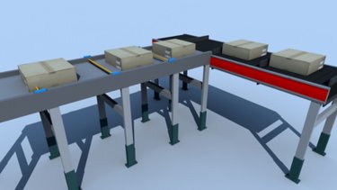
Smartbelt System
Smartbelt is a conveyor system that uses smart belts. Its objective is to organize a queue of products that arrive haphazardly in an orderly position.
Tags:
Software
Languages:
English,
Portuguese
Deploy Time: 60 Minutes
OEM
System Integrator
English
Portuguese
Spanish
Automotive & Tire
Cement
Chemical
Entertainment
Fiber & Textiles
Food & Beverage
Household & Personal Care
Hydrogen
Infrastructure
Life Sciences
Marine
Metals
Mining
Mining, Metals & Cement
Oil & Gas
Power Generation
Print & Publishing
Pulp & Paper
Semiconductor
Water Wastewater
Warehouse & Fulfillment
Implementer
Software
Digital Transformation
Solutions for enabling IT/OT convergence
The Converge IT & OT application helps to simplify and automate industrial data collection through a common information model, mapping and contextualization.
How can I make it work?
What does this application do?
OT/IT Convergence Solution provides the right foundation to drive edge-to-cloud integration at the enterprise level to accelerate IIoT digital transformation. It simplifies and automates collection, contextualization, and organization of industrial equipment data across machines, devices and automation assets at the plant floor while enabling high data integrity.
This is especially useful when working with operational data locked in disparate devices or siloed in systems of record. High-speed, contextualized OT data from controllers is discovered and packaged automatically in a logical, common information model that control engineers can configure. This common information model speeds setup for similar assembly lines and can be enriched with third-party data. It can be mapped to on-prem or cloud applications and easily consumed. Solution unifies data from industrial sources and control or automation systems.
It integrates with a variety of cloud, IIoT, and big data applications including ThingWorx, Microsoft Azure IoT Hub, Microsoft SQL and more. It also uses OPC-DA to access KEPServer Enterprise data for third party connectivity. With access to OT contextualized data, IT applications can help users to extract equipment insights across the enterprise: Quickly, easily and proactively identify process and production inefficiencies and product defects; allowing to focus on using the data to detect and resolve equipment issues and improve production output.
General Features
The OT/IT convergence solution provides the following features:
- Simplifies and automates industrial data collection, contextualization and organization across equipment, devices and automation assets.
- Unlocks key industrial performance insights from OT data.
- Enables high IT data integrity.
- Integrates with a variety of cloud, IIoT and big data applications.
- Reduces the need for IT technical expertise.
- Automatic creation of information, application content and databases.
- Organize large volume of high-speed data with OT-based information models.
- Connect disparate data sources, add application context and enable contextual data delivery.
Advantages
Supports OT/IT collaboration by empowering control engineers to identify the most appropriate data sets and send information directly to the IT layer.
Limitations/Disadvantages
- Licensed software required, subscription only.
- License tag counts are not additive.
- Tags are counted when information models are deployed, a tag used in multiple applications on the same gateway is counted only once.
Downloads
Please note: You will need to agree to the Terms & Conditions for each download.
Need Help?
If you need help with an application or have feedback from the Innovation Center, please contact us.
Is this application relevant to me?
Convergence solutions are suitable for OT engineers interested in automate the contextualization of the operational data as close to the source before populating the information at the IT level for other analytical applications. Typical use case examples:
- Data collection and contextualization.
- Create organization structure aligned with intended data analysis utilization whether via information modeling alone or smart objects and information modeling combined.
- Perform intended data analysis with other analytics software.
Application areas
Food and Beverage, Automotive and Tire, Manufacturing, etc.
Benefits of applications with OT/IT convergence solutions:
- Baseline benefit comes from the information model and ability to contextualize to the asset hierarchy.
- For users that have a Rockwell Automation Integrated Architecture system, additional benefit is realized by adding Smart Objects configuration properties and achieving synchronized data collection at high resolutions.
- The data collection and organization capabilities provide value by empowering OT collaboration with IT and also provides the ability to egress contextualized data sets for big data analysis projects.
- Improve engineering efficiency for project deployment and accessibility to data.
How can I make it work?Requirements: products, tools, prior knowledge.
Hardware:
- PowerFlex 525
- CompactLogix, ControlLogix
- Firmware revision 30 or high.
Software:
- Programs: FTEGSmartObjects.ACD, ACMTR88HMI.apa
- Studio 5000 Logix Emulate v33
- Studio 5000 Logix Designer v34
- FactoryTalk Logix Echo v33.11.00
- Studio 5000 Application Code Manager v4.02.00
- FactoryTalk ViewME v12.00.00
- FactoryTalk Edge Gateway v3.00.00
- ThingWorx 9.0
- FactoryTalk Administration Console v6.30.00
- Microsoft SQL Server Management Studio v18.9.1
- SQLServer/SQLExpress
- Azure IoT Explorer Preview v15.00
- Azure IoT Hub
Previous Knowledge
- Familiarity with control theory, controller coding skills, application knowledge (Preferable OT engineer) that can relate with the intended use case and analysis once the data has reached its intended destination.
- Intermediate knowledge of programming and configuration in Logix Design Studio 5000 software.
Implementation Guide
1. Identify the use cases for implementation:
1.1 Test Client Application
1.2. ThingWorx Application
1.3. SQL Server Application
1.4. Azure IoT Hub Application
Add a driver:
1. Select Data Flow > Data Sources.
2. From Define Drivers, select Add to add a driver to the gateway.
3. From Select Driver, select the driver type to configure:
- FactoryTalk Live Data (FTLD)
- EtherNet/IP (CIP)
4. Select Next.
5. Enter the Driver Name and define the settings.
- The name must contain only letters, numbers, and hyphens.
- The settings differ for each driver type.
6. Select Save.
Add a data source:
1. Select Data Flow > Data Sources, and then from Configure Data Sources, add a data source.
- To add the first data source, select Add Data Sources.
- To add a subsequent data source, select Add.
2. Enter the name and then from Data Browse Path Type, select Logix Project File (FTEGSmartObjects.ACD).
• The name must contain only letters, numbers, and hyphens.
3. Browse for the file path and select the .acd file.
4. (optional) To generate the namespace, select Auto-populate namespace.
5. From Driver for Collection, select the FactoryTalk Live Data or EtherNet/IP (CIP) driver.
6. Enter the collection path.
7. Select Save to add the data source.
Test the application
1. Test Client. The Test Client application displays live data streaming into the gateway when Enable Data Flow is selected.
2. ThingWorx. Collect information from Rockwell Automation and third-party sources and send it to a ThingWorx Foundation server.
3. SQL Server. Provides a method to collect information from Rockwell Automation and third-party sources.
4. Azure IoT Hub.
Solutions for enabling IT/OT convergence
Version 2.0 - August 2026
Solutions for enabling IT/OT convergence
The Converge IT & OT application helps to simplify and automate industrial data collection through a common information model, mapping and contextualization.
Tags:
Software
Languages:
English,
Portuguese,
Spanish
Deploy Time: 60 Minutes
Spanish
Portuguese
English
Food & Beverage
Implementer
Software
Machine & Equipment Builders
Remote variable logging with FactoryTalk Optix
Step-by-step process for generating PDF reports from process variables of a simulated electric motor operation. This application also provides a base framework for developing a first application using FactoryTalk Optix.
What does this application do?
The native generation of PDF reports without coding in FactoryTalk Optix enables automated digitalization of production, audit, and quality control data directly at the Edge. This function is critical for traceability compliance, allowing operators to export summaries of alarms, trends, and historical variables with a single click into a PDF file.
Additionally, the FT Optix application provides a reference framework for building your first FT Optix application.
Is this application relevant to me?
This is useful for users who have questions about how to create their first FT Optix projects, as well as for generating reports of process variables logged remotely from any database.
Application areas: Any type of industry that requires variable logging.
Downloads
Please note: You will need to agree to the Terms & Conditions for each download.
Need Help?
If you need help with an application or have feedback from the Innovation Center, please contact us.
How can I make it work?
Requirements: products, tools, prior knowledge.
Hardware
- Personal computer
Software
- FactoryTalk Optix 1.6+
- Studio 5000
- FT Echo
Background knowledge
- Programming and configuration knowledge in FT Optix and Studio 5000.
Implementation Guide
Glossary of Object Concepts in FactoryTalk Optix
To better understand the objects used in the application, it is recommended to understand their meaning.
- Navigation Panel - A user interface (UI) component designed to manage navigation between different application screens. It allows switching visual containers in an automated and structured manner using native events, enabling efficient and intuitive workflows for the operator without overloading the rendering thread.
- Panel (Type) - A base visual node that acts as a general-purpose container in the user interface. As it is treated as a Type, it allows inheritance, mass instantiation, and the creation of custom templates (widgets). It can host local logic, variable collections, or complex layouts, serving as a modular building block of the interface.
- DataGrid - An advanced tabular visual component designed for real-time visualization and editing of large volumes of structured data (such as database records, controller arrays, or alarm lists). It supports dynamic binding to data models (Model) and direct interaction with rows/columns exposed as objects within the session information model.
- GridLayout - A UI layout control that automatically organizes its child nodes into a two-dimensional matrix structure of flexible or fixed-size rows and columns. It optimizes High-Performance HMI design, ensuring that diagnostic visual elements maintain consistent proportions and strict alignment when screen resolution changes or during remote web access.
- Data Logger - A core module of FactoryTalk Optix responsible for sampling, storing, and transferring historical process and status variables into a data store. It supports time-based (periodic) or event-based (change-of-state) triggers, natively translating controller tags into relational structures compatible with IT systems.
- Datalog Embedded - A specific storage engine configuration in which the history collected by the Data Logger is directly written to a local runtime database based on SQLite technology. This solution does not require external servers, making it ideal for Edge applications or closed devices such as OptixPanel, operating efficiently within the token-based licensing model (included with Data Logger).
- Reports - A native component and rendering engine responsible for automated generation and export of reports in PDF format based on visual design templates (UI). It allows associating model variables and dynamic SQL queries directly with the final document for audit, quality control, and regulatory compliance (such as CFR21 Part 11).
Model Configuration (Studio)
To create and configure a PDF report using the native functions and interconnections of the Information Model in FactoryTalk Optix Studio, follow these steps:
Instantiate the Reports Engine and Visual Template
- In the Project Panel, expand the main node of your project.
- Right-click on the Reports folder (or on the root of the project) and select New -> Report. A new node will be created that will act as the generation engine. Name it Reports1.
- When creating the report, a child visual container is automatically added under the UI folder. Expand UI -> Reports and locate the associated visual panel (usually named Reports1). This is the report template.
- Double-click on this visual panel to open the graphical editor. Design the report format using High-Performance HMI guidelines:
- Insert a Label object in the Header section for the report title (e.g., "OEM Company Buenos Aires, Argentina") and other elements that appear below.
export-report-variables-from-factorytalk-optix_Image 1.jpg
- In the Sections area, insert a DataGrid component to display historical tabular data.
export-report-variables-from-factorytalk-optix_Image 2.jpg
Link Data to the Report (Native Data Binding)
- Select the DataGrid component that you inserted within the report visual template.
- In the Properties panel (on the right), locate the Model property.
- Click on the dynamic link icon (the Dynamic Link indicator diamond).
- Navigate through the Information Model tree and point directly to your historical data source, for example: Model/DataLoggers/PlantDataLogger/DatalogEmbedded (or the Store table associated with the Data Logger).
- The component will automatically map the relational database columns (timestamps, process variables, states) within the report view.
Configure the Generation Trigger in the UI (Trigger) and Configure the PDF Output Parameters
- Go to UI -> MainWindow (Type) and add a Panel object (Type) named Report (Type) where the print button will be placed.
- Insert a Button component and change its text to "Generate PDF Report".
- Select the button, go to the Properties panel and locate the Events section.
- In the MouseClick event, click the + button to add a new native action.
- Select the ExecuteMethod action.
- In the Method field, click the Information Model selector, navigate to your report node (Reports/Reports1) and select the native method GeneratePdf.
- OutputPath: Path and name of the output file. To make it dynamic and compatible with any platform (Windows/Linux/OptixPanel), use the Runtime local storage syntax: Path\MotorStatusReport.pdf.
export-report-variables-from-factorytalk-optix_Image 3.jpg
Run the FT Optix Emulator, establish connection with FT Echo and Studio 5000, and press the button after changing some motor variables.
export-report-variables-from-factorytalk-optix_Image 4.jpg
export-report-variables-from-factorytalk-optix_Image 5.jpg
export-report-variables-from-factorytalk-optix_Image 6.jpg
export-report-variables-from-factorytalk-optix_Image 1.jpg
export-report-variables-from-factorytalk-optix_Image 2.jpg
export-report-variables-from-factorytalk-optix_Image 3.jpg
export-report-variables-from-factorytalk-optix_Image 4.jpg
export-report-variables-from-factorytalk-optix_Image 5.jpg
export-report-variables-from-factorytalk-optix_Image 6.jpg
factorytalk-optix-condition-monitoring-dashboards_16x9-optix_monitoreo_step1_image17.jpg
Remote variable logging with FactoryTalk Optix
Version 1.0 - June 2026

Remote variable logging with FactoryTalk Optix
Step-by-step process for generating PDF reports from process variables of a simulated electric motor operation. This application also provides a base framework for developing a first application using FactoryTalk Optix.
Tags:
Software
Languages:
Spanish,
Portuguese,
English
Deploy Time: 30 Minutes
English
Portuguese
Spanish
Aerospace
Airports & Airlines
Automotive & Tire
Cement
Chemical
Entertainment
Fiber & Textiles
Food & Beverage
Household & Personal Care
Hydrogen
Infrastructure
Life Sciences
Marine
Metals
Mining
Mining, Metals & Cement
Oil & Gas
Power Generation
Print & Publishing
Pulp & Paper
Semiconductor
Water Wastewater
Warehouse & Fulfillment
Mass Transit
Renewable Energy
Manufacturing
Waste Management
Implementer
Software
Process Solutions
PID Simulation with Lead/Lag and 1st Order Filter
This application uses a model to generate a random value for a process variable, which can be used for visualization or PID controller simulation.
What does this application do?
This is a simplified application for simulating the behavior of a process variable to be connected to a PID controller. This application includes executable files to perform this simulation in Studio5000 for use with Logix processors.
Is this application relevant to me?
This application can be used in Studio 5000 for Logix processors. It allows you to understand the effect of gains and different PID configuration parameters, as well as simulate simple processes for demonstration or virtual commissioning purposes.
Downloads
Please note: You will need to agree to the Terms & Conditions for each download.
Need Help?
If you need help with an application or have feedback from the Innovation Center, please contact us.
General Features
In the case of Studio 5000, this application uses a Lead-Lag process block.
This will allow us to simulate the behavior of a temperature control system.
pid-simulation-with-lead-lag-and-1st-order-filter_Fig 1
pid-simulation-with-lead-lag-and-1st-order-filter_Fig 2
The steady-state error is adjusted using the Gain parameter within the LDLG instruction.
The phase delay is adjusted using the Lag parameter within the LDLG instruction.
pid-simulation-with-lead-lag-and-1st-order-filter_Fig 3
pid-simulation-with-lead-lag-and-1st-order-filter_Fig 4
Advantages
- Simplified code
- Ease of implementation
- Impact on development time
- Cost Reduction
- Operational Efficiency
- Enables simulation and study in a secure environment
How can I make it work?
Requirements: products, tools, prior knowledge.
Software
- Studio 5000 – Logix Designer (V36.0→)
Prior Knowledge
- Basic knowledge of Studio 5000.
- Knowledge of PID Closed Loop Control Systems.
Links of Interest (internal or external)
- https://www.rockwellautomation.com/es-mx/products/software/factorytalk/designsuite/studio-5000.html
- https://www.rockwellautomation.com/es-mx/capabilities/industrial-automation-control/design-and-configuration-software.html
Implementation Guide
Implementation guide for Studio 5000.
Create a Periodic Task.
For this exercise, a 10ms trigger is used, but this time can be adjusted according to the type of process you want to simulate.
pid-simulation-with-lead-lag-and-1st-order-filter_Fig 5
Create a Function Block Diagram type routine.
pid-simulation-with-lead-lag-and-1st-order-filter_Fig 6
Insert the PID and LDLG instructions as shown below.
pid-simulation-with-lead-lag-and-1st-order-filter_Fig 7
On the line connecting the LDLG block output to the PID PV, right-click and select “Assume Data Available”.
This is an important step because otherwise the controller will flag an error due to its inability to resolve the loop between these two blocks.
pid-simulation-with-lead-lag-and-1st-order-filter_Fig 8
Adjust the PID parameters and gains according to the process you wish to simulate.
pid-simulation-with-lead-lag-and-1st-order-filter_Fig 9
With this parameterization, an underdamped system with an overshoot of approximately 20% is achieved, reaching stability in three half-cycles.
However, it can be adjusted to obtain any desired behavior according to the process being simulated.
| 0 < ζ < 1 | Underdamped System |
| ζ = 1 | Critically Damped System |
| ζ > 1 | Overdamped System |
pid-simulation-with-lead-lag-and-1st-order-filter_Fig 10
pid-simulation-with-lead-lag-and-1st-order-filter_Fig 5
pid-simulation-with-lead-lag-and-1st-order-filter_Fig 6
pid-simulation-with-lead-lag-and-1st-order-filter_Fig 7
pid-simulation-with-lead-lag-and-1st-order-filter_Fig 8
pid-simulation-with-lead-lag-and-1st-order-filter_Fig 9
pid-simulation-with-lead-lag-and-1st-order-filter_Fig 10
PID Simulation with Lead/Lag and 1st Order Filter
Version 1.2 - July 2026

PID Simulation with Lead/Lag and 1st Order Filter
This application uses a model to generate a random value for a process variable, which can be used for visualization or PID controller simulation.
Tags:
Software
Languages:
English,
Portuguese,
Spanish
Deploy Time: 60 Minutes
English
Spanish
Portuguese
Implementer
Hardware
Software
Industrial Automation & Control
Solids Pumping Station
Typical development for a solids pumping station, using Studio 5000 and FactoryTalk Optix.
What does this application do?
This application allows for monitoring, even remotely, the status and operating time of the equipment in a solid pumping plant.
General Features
This development includes the following:
- Program configuration in Studio 5000.
- Screen configuration in FactoryTalk Optix.
Advantages:
- Provides an initial reference for solids pumping developments.
- Allows for remote monitoring of the system.
Limitations/Disadvantages - Limited to pumping plants with the same type of equipment.
Is this application relevant to me?
If you need to implement a panel to monitor the operation of solids pumping stations and similar ones that contain the same type of equipment.
Application Areas: It can be applied in liquid processing environments.
Downloads
Please note: You will need to agree to the Terms & Conditions for each download.
Need Help?
If you need help with an application or have feedback from the Innovation Center, please contact us.
How can I make it work?
Requirements: products, tools, prior knowledge.
Hardware
- Any Logix Controller
- Any Optix Panel or PC
Software
- Studio 5000 (the program is developed in version 36)
- Factorytalk Optix (the program is developed in version 1.6)
Prior knowledge
- Basic knowledge of programming and configuration in:
- Studio 5000
- FactoryTalk Optix
- Ladder logic
- Block diagrams
Implementation Guide
Studio 5000 Program
1 - Extract the programs:
solids-pumping-station_16x9-solids-pumping-step1_image1.jpg
Studio 5000 Program
2 - Open the Studio 5000 program.
For testing this application, a 1756-L81E controller was used, with analog and digital modules.
solids-pumping-station_16x9-solids-pumping-step1_image2.jpg
Studio 5000 Program
3 - Review how the tasks are organized, according to what they do:
a) Reading of inputs and outputs
b) Tank Tk01, with an agitator
c) Valve TK600, regulates the water outlet from the storage tank
d) Pump600 and Pump601, pumping to the tank with agitator
e) Pump602 pumps to the filter press
solids-pumping-station_16x9-solids-pumping-step1_image3.jpg
Studio 5000 Program
4 - Identify the tags that will need to be linked in Optix development.
a) PV600.Out_Open
b) SolidsTkDrive_Motor.Sts_Running
c) SolidsTkDrive_Motor.Sts_Stopped
d) P600_Motor.Out_Run
e) P600_RunTime
f) P601_Motor.Out_Run
g) P601_RunTime
h) P602_Motor.Out_Run
i) P603_RunTime
FactoryTalk Optix Program
1 - Open the downloaded folder "Solids_Pumping_rev0".
solids-pumping-station_16x9-solids-pumping-step2_image1.jpg
FactoryTalk Optix Program
2 - Inside the folder, open the "FactoryTalk Optix" file Solids_Pumping_rev0.
solids-pumping-station_16x9-solids-pumping-step2_image2.jpg
FactoryTalk Optix Program
3 - Configure Ethernet IP communication.
solids-pumping-station_16x9-solids-pumping-step2_image3.jpg
FactoryTalk Optix Program
4- Import the necessary tags from the Studio 5000 program to display if the equipment is running and for how long.
solids-pumping-station_16x9-solids-pumping-step2_image4.jpg
FactoryTalk Optix Program
5 - Review the hierarchy, which shows the elements used to create the screen.
solids-pumping-station_16x9-solids-pumping-step2_image5.jpg
FactoryTalk Optix Program
6 - Modify the graphic elements according to the changes you wish to make.
solids-pumping-station_16x9-solids-pumping-step2_image6.jpg
solids-pumping-station_16x9-solids-pumping-step1_image1
solids-pumping-station_16x9-solids-pumping-step1_image2
solids-pumping-station_16x9-solids-pumping-step1_image3
solids-pumping-station_16x9-solids-pumping-step2_image1.jpg
solids-pumping-station_16x9-solids-pumping-step2_image2.jpg
solids-pumping-station_16x9-solids-pumping-step2_image3.jpg
solids-pumping-station_16x9-solids-pumping-step2_image4.jpg
solids-pumping-station_16x9-solids-pumping-step2_image5.jpg
solids-pumping-station_16x9-solids-pumping-step2_image6.jpg
Solids Pumping Station
Version 1.0 - August 2026
Solids Pumping Station
Typical development for a solids pumping station, using Studio 5000 and FactoryTalk Optix.
Tags:
Hardware,
Software
Languages:
English,
Spanish,
Portuguese
Deploy Time: 60 Minutes
English
Portuguese
Aerospace
Automotive & Tire
Cement
Chemical
Entertainment
Fiber & Textiles
Food & Beverage
Household & Personal Care
Hydrogen
Infrastructure
Life Sciences
Marine
Metals
Mining
Mining, Metals & Cement
Oil & Gas
Power Generation
Print & Publishing
Pulp & Paper
Semiconductor
Water Wastewater
Warehouse & Fulfillment
Mass Transit
Renewable Energy
Implementer
Software
Machine & Equipment Builders
Center driven Winder and Unwinder application
Sample code for variable diameter spindle based on tension feedback from a load cell, uses Torque Regulator to control web tension of material in center driven.
What is this for?
A winder and unwinder machine are essential in various industries, particularly in the manufacturing and processing of web materials such as paper, film, textiles, rubber, wire, tape, etc.
These machines are used to wind and unwind continuous rolls of material, facilitating efficient production, storage, and transportation.
Winder is designed to wind the web material onto a core or a spool, creating a tightly wound roll.
Unwinder on the other hand, is used to unroll or unwind the material from a roll, feeding it into the downstream processes or applications.
This sample code shows us how to use it in applications with variable diameter spindle based on tension feedback from a load cell, uses Torque Regulator to control web tension of material in center driven.
General Features:
- Center Driven application.
- Torque control for Winder, Unwinder drives.
- Speed Limited Adjustable Torque
- Speed control for the puller drive.
- Speed follows a virtual axis.
- Tension control at line speed.
- Full tension control when accelerate and decelerate.
- Flexible parameters
- Reference speed of machine.
- Acceleration time.
- Deceleration time.
- Roll Unwind tension control.
- Roll Wind tension control.
- Roll length control.
- Roll diameter control.
- Drive status, Alarms and Faults.
Advantages:
The Winders controlling web tension in a center driven has excellent accuracy of torque control for web material.
- Flexible, Predictive Diagnostics, Integrated Safety.• Automatic Device Configuration.
- Integrated Architecture.
- Speed Limited Adjustable Torque.
Limitations / Disadvantages
- Drive for Unwinder and Winder must have torque control.
- Controller must at least 1769-L19 or above.
- Must adapt the application if use Surface Driven.
Is this useful for me?
In general, systems can be recommended to customers, OEM manufacturers,
Use when:
- Controlling web tension in a center driven (un)winder.
- Torque Control to control web tension.
- Tension feedback device is a load cell or a dancer.
Do NOT use when:
- Speed Trim Regulator to control web tension is preferable is over Torque control.
- Drive has no torque control feature.
- Surface driven for Winder or Unwinder. Must adapt the application to calculate it.
Application areas
Web Material, CPW, Converter, Printer, Metals, Plastics
Benefits of application:
- Center driven winders have the benefit of controlling tension via directly controlling the torque of the wound product.
- Tension taper can be applied as the diameter increases.
- Flexible control and production gain and speed.
- Increased dynamism in production.
- Full tension control when accelerate and decelerate machine.
- Automatic Device Configuration, if have any problem with devices. This feature reduces downtime of process.
- Control length of product by tracking material.
- Control Diameter of product if include sensor diameter.
How can I make it work?
Hardware:
- CompactLogix 1769-L19ER, 5069-L310ER or high
- PowerFlex 753 or PowerFlex 755.
- PowerFlex 525.
- PanelView 800.
- CR30.• Firmware revision 30 or high
Software:
- Logix Design Studio 5000 version 30 or higher.
- Connected Component Workbench, version 21 or higher.
- Winder_Unwinder.ACD.
- WinderUnwinder.ccwarc.
Previous Knowledge
Basic knowledge of programming and configuration in Logix Design Studio 5000 software:
Basic knowledge of programing and configuration in Connected Component Workbench software:
- PowerFlex 525 configuration.
- PowerFlex 753 and PowerFlex755 configuration.
- PanelView 800 configuration.
- CR30 configuration.
- Ladder language (LD), Function Block Diagram (FBD)
Knowledge about Drive System, Speed, Torque, Position Control.
Downloads
Please note: You will need to agree to the Terms & Conditions for each download.
Need help?
If you need help with an application or have feedback from the Innovation Center, please contact us.
Installation Guide
Step 1
1. Open program Winder_Unwinder.ACD – This file is located on Generalfiles.
Step 2
Assign static IP address and last firmware version for all components of the architecture.
PowerFlex 525
https://literature.rockwellautomation.com/idc/groups/literature/documents/um/520com-um001_-en-e.pdf#page=29
https://rockwellautomation.custhelp.com/app/answers/answer_view/a_id/546043/loc/en_US
PowerFlex 75x
CR30
https://rockwellautomation.custhelp.com/app/answers/answer_view/a_id/702836/loc/en_US
https://literature.rockwellautomation.com/idc/groups/literature/documents/um/440c-um001_-en-p.pdf#page=106
PanelView 800
1.1 Communication Settings, Configure PanelView 800: Go to the main configuration screen.
1.2 Press terminal settings.
1.3 Press Communication.
Step 3
Download application for controller.
- From the Communications menu, choose Who Active to open the Who Active dialog box.
- From the navigation pane, find the path between your Workstation and the target Logix controller for this project.
- Click Download to open the Download dialog box.
Step 4
Repeat this step, for another PowerFlex 75x drives.
Step 5
Download application for CR30
After the download is complete, the I/O Not Responding indicator flashes.
A warning icon appears on the CR30 safety relay in the I/O Configuration tree.
The module fault is Code 16#0106 as the configuration in the Logix controller for the safety relay CR30 does not match what is in the physical device.
- Double-click the safety relay profile.
- Click the Logic Configuration tab. The Project Mismatch dialog box opens. Click Download the current project to the safety relay.
- The Change to Program Mode dialog box appears. Click Yes
- The Download Success dialog box appears. Click Yes.
- Once the download is complete, the I/O connection between the Logix controller and the I/Os is successful.
Step 6
Open and Download for PanelView 800 the HMI application.
- Open program Connect Components Workbench - CCW
- Open program WinderUnwinder.ccwarc – This file is located on Generalfiles.zip.
- Download the application to the PanelView 800 and execute it.
Step 7
Configure the application according to your respective project.
For all drives, you must configure:
- Motor Speed (rpm).
- Motor Frequency (Hz).
- Roll Diameter (mm).
- Gear ratio
When the PanelView 800 is running you have this screen to configure all these parameters:

Center driven Winder and Unwinder application
Sample code for variable diameter spindle based on tension feedback from a load cell, uses Torque Regulator to control web tension of material in center driven.
Tags:
Software
Languages:
English,
Portuguese
Deploy Time: 120 Minutes
OEM
System Integrator
English
Portuguese
Spanish
Automotive & Tire
Cement
Chemical
Entertainment
Fiber & Textiles
Food & Beverage
Household & Personal Care
Hydrogen
Infrastructure
Life Sciences
Marine
Metals
Mining
Mining, Metals & Cement
Oil & Gas
Power Generation
Print & Publishing
Pulp & Paper
Semiconductor
Water Wastewater
Warehouse & Fulfillment
Implementer
Software
Industrial Automation & Control
MicroLink Remote Control, MicroLink MQTT Remote Control
Streamline IoT in industrial environments. Unlock MQTT capabilities effortlessly through Micro800 controllers.
MicroLink MQTT is a transformative suite of User-Defined Function Blocks (UDFBs) for Micro800 controllers, enabling seamless MQTT communication with any MQTT broker. This package includes three function blocks: one for establishing connections, one for subscribing to specific topics, and one for publishing data. It offers high customizability with settings for unique MQTT IDs, broker/server IP addresses, usernames, passwords, and your chosen Quality of Service (QoS).
Target to use with PowerFlex 523 and 525 component drives from Rockwell Automation.
This code can be used with the following equipment:
- PowerFlex 523
- PowerFlex 525
- Micro850
- Micro870
- PanelView 800d
What does this application do?
MicroLink MQTT is a UDFBs suite designed for seamless integration with Micro800 controllers from Rockwell Automation. It's meant to enhance the capabilities of these controllers by enabling MQTT communication with any MQTT broker.
This solution is especially useful for remote control use cases and in the industrial field where data exchange and communication efficiency are critical. MicroLink MQTT provides three function blocks for establishing connections, subscribing to specific topics, and publishing data.
With MicroLink MQTT, users can easily establish a connection to an MQTT broker, subscribe to the data they need, and publish data back to the broker. It offers high customization options for MQTT IDs, broker/server IP addresses, usernames, passwords, and your chosen Quality of Service (QoS), ensuring efficient and secure data communication.
Therefore, whether you're an industrial operator looking to optimize data communication or a developer who needs to integrate efficient data exchange in your applications, MicroLink MQTT can be the perfect solution.
General Features
Our package provides three core User-Defined Function Blocks:
- RA_MQTT_CONNECT_v2: Step into the future with our connection function block. It lets your Micro800 controller establish a connection with an MQTT broker, setting the stage for robust data interchange.
- RA_MQTT_SUBSCRIBE_v2: Leverage our subscription function block to stay connected with the data you need. Tailor your subscriptions to specific topics from the MQTT broker and always keep your operations data-rich and up-to-date.
- RA_MQTT_PUBLISH_v2: Take control with our publish function block. Transmit data with precision by publishing topics to the MQTT broker, making your data-driven operations a benchmark for others to follow.
Each function block is highly customizable, allowing you to specify unique MQTT IDs, broker/server IP addresses, usernames, passwords, and your preferred Quality of Service (QoS). With RA_MQTT v2, every aspect of your MQTT communications is in your hands.
Limitations / Disadvantages
- Limited to Micro820, Micro850 and Micro870
- Third-party MQTT broker dependent
Downloads
Please note: You will need to agree to the Terms & Conditions for each download.
Need Help?
If you need help with an application or have feedback from the Innovation Center, please contact us.
How can I make it work?
Requirements: products, tools, prior knowledge.
Hardware
- The architecture implies using Micro820, Micro850, Micro870 hardware.
Software
- Connected Component Workbench, version 21 or higher.
- The firmware of the equipment used must be compatible with the version of Connected Component Workbench.
- User-defined Function Blocks:
- RA_MQTT_CONNECT_v2
- RA_MQTT_SUBSCRIBE_v2
- RA_MQTT_PUBLISH_v2
Prior Knowledge
A foundational understanding of ladder programming and system configuration using the Connected Components Workbench software is highly recommended. Additionally, familiarity with MQTT protocols would be beneficial.
Implementation Guide
Establishing Connection Settings to Connect to or Disconnect from a MQTT Broker
An MQTT broker essentially serves as a server to manage MQTT messages. To connect to an MQTT broker, we must input the broker's IP address and port number into the RA_MQTT_CONNECT_v2 UDFB. The broker could be housed on your computer (in which case you would need to install and operate an MQTT broker compatible with your OS), or it could be a remote server, such as the ones previously mentioned.
1.1 Assign the IP address and port number of the MQTT broker to your RA_MQTT_CONNECT_v2 UDFB
This example is for connecting to the test.mosquitto.org broker in the cloud. An alternative to entering the IP address directly is to enable Domain Name Service (set ‘EnableDNS’ TRUE) after entering in the MQTT broker URL into ‘MQTTBrokerName’ and the local DNS server IP address into ‘DNSIPaddr’ in rung 2.
1.2 Enter a unique ‘clientName’, as well as a ‘userID’ and ‘userPass’ if your MQTT broker requires it. (Many public MQTT brokers do not require a username and password, so these fields are optional and can be left blank if not required.)
1.3 Set ‘EnableMQTT’ to TRUE to connect to the MQTT broker.
Note:
There are a few things to keep in mind to ensure a successful connection. The MQTTsocketSts should eventually display a 9. If it shows a 7 and then reverts back to 0, it could imply that your broker is either not running or doesn't exist.
The data in resultData_Out is helpful for diagnostic troubleshooting. Typically, when you send a connect command to the server, the server responds with an acknowledgement. The acknowledgement is indicated by the 1st byte, which in this instance, is '32'.
Another frequent response you'll receive is a ping acknowledgement, denoted by '208' in the 1st byte of the returned data. The ping command is sent to the remote broker at 50-second intervals. This interval is hardcoded in the UDFB but can be modified if needed.
If the return data is something other than 32 or 208 upon connection, it could suggest that the client has subscribed to a topic that was broadcasted while it was offline. The message is retained and sent to the client when it comes back online. If you encounter this, process the message and then reinitialize the connection.
1.4 If you want to configure for LWT, you need to access these parameters in the UDFB:
322| willTopic := willTopic_In;
323| willData := willData_In;
‘willTopic_In’ is where you enter the Last Will topic for the connection.
‘willData_In’ is where you enter the testament for the connection.
The MQTT broker will publish the testament to all clients that subscribe to the Last Will topic when the client is disconnected abruptly.
1.5 If you want to disconnect gracefully from the server (without triggering LWT), set ‘disconnect_Cmd’ to TRUE.
This is a rising edge triggered bit, so you can reset it immediately.
Subscribing to or Unsubscribing from a Topic
The MQTT protocol exchanges data through subscribe and publish methods. Clients communicate directly only with the MQTT broker. Clients subscribing to a topic will receive a message from the broker when another client publishes to that topic. Clients can be of any form as long as they have a running MQTT client application. For example, it could be software on a PC, a connector or API for the software, an app on a phone, or application code on a PLC.
2.1. Enter the name of the topic (‘topicName_input’) to subscribe to or unsubscribe from.
2.2. Set the quality of service (‘subQoS’) for the subscription. By default, use ‘0’ as it consumes the least bandwidth.
2.3. Set ‘subscribe’ or ‘unsubscribe’ to TRUE to subscribe to or unsubscribe from the topic.
2.4. These bits detect for rising edge, so you can reset them immediately.
2.5 Notice that the resultData_Out from RA_MQTT_CONNECT_v2 is also copied to respondData_In.
Note:
It is recommended to use only 1 instance of each UDFB.
Publishing a Topic
When a topic with data is published to an MQTT broker, the broker then forwards this topic data to all the clients subscribed to it. The client that publishes the message does not know if any remote nodes receive the topic, as that responsibility lies with the broker, depending on the QoS level. Topics can be published or subscribed to at any QoS level, but they will only be delivered at the lowest QoS level.
3.1. Enter the topic to publish into ‘pubTopic_In’.
3.2. Enter the data for the topic into ‘pubData_In’.
3.3. Set the quality of service into ‘pubQoS’. By default, use ‘0’ as it consumes the least bandwidth.
3.4. Set ‘publish’ to TRUE to publish the topic with its data. It will automatically will be set back to FALSE when ‘publishDN’ becomes TRUE.
3.5. Notice that the resultData_Out from RA_MQTT_CONNECT_v2 is also copied to respondData_In.
Getting Messages from Subscribe Topics
The MQTT broker handles all topic subscriptions. It sends the data of any published topic to the clients that are subscribed to it. When a topic is received by the Micro800 MQTT client, it populates the 'TopicName' and 'TopicData' array variables in the RA_MQTT_CONNECT_v2 UDFB. The data is stored in a First In/First Out order, so it is crucial to process the data before it gets overwritten.
Subscribing to an Array of Topics
MQTT_Subscriptions is an optional Structured Text program that works in conjunction with the MQTT_Client program. It enables you to subscribe to a 'Subscriptions' array of preconfigured topics. Adjust the array dimension of the global variable 'Subscriptions' to the desired size and modify the initial value of the local variable 'maxSubscriptions' to match the array size (default=10). 'Subscriptions' is a User-Defined Data Type (UDT) array that comprises the MQTT topic 'Name', the latest topic 'Data', a timestamp based on the RTC value when the latest topic 'Data' was received, and a 'Subscribed' indicator. Enter the desired topic names to subscribe to as initial values for Subscriptions[i].Name before downloading the project to the controller.
Local variable 'enableSubcriptions' must be TRUE in order to enable this functionality.
Automatically Publishing an Array of Topics
MQTT_Publications is an optional Structured Text program that works in conjunction with the MQTT_Client program. It allows you to publish an entire 'Publications' array of preconfigured topics. Adjust the array dimension of the global variable 'Publications' to the desired size and modify the initial value of the local variable 'maxPublications' to match the size of the array (default=10). 'Publications' is a User-Defined Data Type (UDT) array that comprises the MQTT topic 'Name', the latest topic 'Value', the previous topic value 'Valueprev', and a timestamp based on the RTC value when the latest topic 'Value' was published. Enter the desired topic names to publish as initial values for Publications[i].Name before downloading the project to the controller.
Set the local variable 'ChangeOfState' to TRUE to publish any value that changes on an exception basis. Set the local variable 'Interval' to TRUE and 'intervalTime' to a non-zero value to publish all of the current values that aren't null ('') on a timed interval basis. Typically, one would choose either 'ChangeOfState' or 'Interval' as the method for publishing topic updates. For a one-time update, set the local variable 'OnDemand' to TRUE to publish all current values that aren't null (''). 'OnDemand' is set to FALSE once the entire 'Publications' array has been published. The local variable 'enablePublications' must be set to TRUE to enable this program functionality.
MicroLink Remote Control, MicroLink MQTT Remote Control
Version 2.0 - September 2026
MicroLink Remote Control, MicroLink MQTT Remote Control
Streamline IoT in industrial environments. Unlock MQTT capabilities effortlessly through Micro800 controllers.
Tags:
Software
Languages:
English,
Portuguese,
Spanish
Deploy Time: 60 Minutes
English
Food & Beverage
Implementer
Hardware
Software
Tank Sequences with Library Sequencer
Implementation of process sequences with PlantPAx using Studio 5000 and FactoryTalk View for standardized and reusable control.
What does this application do?
This document describes the implementation of a process strategy using the Sequencer library for industrial processes using PlantPAx technologies, in conjunction with Studio 5000 Logix Designer and FactoryTalk View.
Its purpose is to serve as a practical reference guide for the development of sequence-based applications, enabling the construction of standardized, reusable, and scalable solutions, aligned with best practices in industrial automation.
Using this approach, it is possible to:
- Reduce complexity during development
- Improve system maintainability
- Ensure consistent operation across different processes or plant units
Is this application relevant to me?
This solution is geared towards different profiles within the industrial environment:
- Automation engineers - It allows the implementation of control strategies in a structured way using standard PlantPAx libraries, facilitating the development of modular logic that is organized and aligned with modern distributed control architectures.
- Plant operators - It provides intuitive and consistent graphical interfaces for monitoring and controlling sequences, improving process visibility, reducing operational errors, and facilitating interaction with the system.
Downloads
Please note: You will need to agree to the Terms & Conditions for each download.
Need Help?
If you need help with an application or have feedback from the Innovation Center, please contact us.
How can I make it work?
Requirements: products, tools, prior knowledge.
To implement this solution, the following environment is required:
- Hardware:
- ControlLogix/CompactLogix Controller
- HMI Station
- Software:
- Studio 5000 Logix Designer
- FactoryTalk View
- PlantPAx Process Library
Implementation Guide
Definition of devices: valves, pumps and sensors.
Studio5000
It is assumed that the project already has the necessary equipment connected and created in the Studio5000 program, which in this case will be: 5 valves, 1 level sensor, and 2 pumps, and that these are already imported into the sequencer routine that is already within the PlantPAx libraries, named: CS_raP_Opr_Seq
tank-sequences-with-library-sequencer_Imagen2.png
Import Sequencer routine from PlantPAx into Studio 5000.
In Studio 5000 Logix Designer:
- Import from the PlantPAx libraries the routine: P_Seq (CS_raP_Opr_Seq)
- Select the corresponding routine
tank-sequences-with-library-sequencer_Imagen3.png
Assign a representative name according to the process (e.g., A03_RTANK).
tank-sequences-with-library-sequencer_Imagen4.png
Configure digital and analog inputs and outputs.
Within the created routine, the main blocks are identified:
Input Block
- Signals from sensors or process conditions.
tank-sequences-with-library-sequencer_Imagen5.png
Digital output block
- Valve and pump control
tank-sequences-with-library-sequencer_Imagen6.png
Analog output block
- Continuous control signals
tank-sequences-with-library-sequencer_Imagen7.png
Optimize Ladder logic for multiple devices.
For multi-device applications:
- It is recommended to implement additional logic in Ladder Diagram
- Group signals to optimize bit usage
- Simplify integration with the sequencer
This improves scalability and facilitates maintenance.
tank-sequences-with-library-sequencer_Imagen8.png
Develop HMI in FactoryTalk View using Global Objects.
In FactoryTalk View:
- Open the HMI project
- Verify that the PlantPAx libraries are available
Once the PlantPAx libraries are inside our project in View, we go to the Global Objects section and locate the project with the name: (raP-5_20-SE) Graphic Symbols - raP_Opr_Seq
tank-sequences-with-library-sequencer_Imagen9.png
Insert the sequencer graphic object into the display.
tank-sequences-with-library-sequencer_Imagen10.png
Associate parameters between HMI and logic.
- Access the option: Global Object Parameter Value.
- Link the graphic object to the controller routine.
This enables interaction between HMI and control logic.
tank-sequences-with-library-sequencer_Imagen11.png
Load the project into Client.
Check Sequencer blocks.
When we open the file for studio5000 we have the following:
tank-sequences-with-library-sequencer_Imagen12.png
Then, when we open the Normal section in the tree, we find the routine where the sequence is created, which is named A03_RTANK:
tank-sequences-with-library-sequencer_Imagen13.png
Within the program (e.g., A03_RTANK), the main blocks are found:
- Tickets
- Confirmation (Prompt)
- Sequence motor
- Digital outputs
- Analog outputs
tank-sequences-with-library-sequencer_Imagen14.png
Accessing the HMI application.
When you open the corresponding file (for example: “PlantPAx Sequencer.cli”), the main screen (Overview) appears, which displays:
- General state of the system
- Process indicators
- Control button for executing the sequence
This screen serves as the central point of interaction for the operator.
Now, when we open the file “PlantPAx Sequencer.cli” we have the following:
tank-sequences-with-library-sequencer_Imagen15.png
In which we can see the Overview of the experience, as well as the button which we will use to start the sequence.
Login.
Before operating the system:
- Select the security icon (key) located at the top of the interface
- Log in with an authorized user
This step is important because many sequencer actions require operating permissions.
tank-sequences-with-library-sequencer_Imagen16.png
Sequencer Initialization.
Once logged in:
- Press the sequence start button available on the main screen
At this point, the system is ready to execute the logic defined in the controller.
tank-sequences-with-library-sequencer_Imagen17.png
Sequence Inspection.
To analyze the sequencer's behavior:
- Select the inspection button (magnifying glass icon with document)
This allows access to the detailed view of the sequencer, where you can see:
- Current states of the sequence
- Configured steps
- Active transitions.
tank-sequences-with-library-sequencer_Imagen18.png
Review of sequence properties.
Within the detail view:
- Access the “Starting” section (or corresponding initial stage)
- Here you can review the properties of each step, including:
- Related entries
- Conditions necessary to advance to the next stage
- Digital outputs
- Actuation of valves, pumps or other devices
- Analog outputs
- Continuous control variables, if configured
This analysis allows validating the correct configuration and behavior of the process.
Process Execution.
To execute the sequence:
- Press the Start button within the sequencer interface
When running for the first time, it is recommended to validate that all initial conditions of the process are in a safe state.
Once started:
- The sequencer will begin executing each step sequentially.
- The transitions will depend on the conditions configured in the logic
tank-sequences-with-library-sequencer_Imagen19.png
To run the sequence, simply click the start button when opening the sequence for the first time.
Monitoring of execution.
During the operation, it is recommended to:
- Monitor progress between steps
- Check for changes in:
- Inputs (sensors)
- Digital outputs (actuators)
- Analog variables
- Confirm that there are no alarms or failure conditions
tank-sequences-with-library-sequencer_Imagen20.png
tank-sequences-with-library-sequencer_Imagen2.png
tank-sequences-with-library-sequencer_Imagen3.png
tank-sequences-with-library-sequencer_Imagen4.png
tank-sequences-with-library-sequencer_Imagen5.png
tank-sequences-with-library-sequencer_Imagen6.png
tank-sequences-with-library-sequencer_Imagen6.png
tank-sequences-with-library-sequencer_Imagen8.png
tank-sequences-with-library-sequencer_Imagen9.png
tank-sequences-with-library-sequencer_Imagen10.png
tank-sequences-with-library-sequencer_Imagen11.png
tank-sequences-with-library-sequencer_Imagen12.png
emergency-stops-for-machinery-and-equipment-retrofit-with-programmable-safety-relays-img10
emergency-stops-for-machinery-and-equipment-retrofit-with-programmable-safety-relays-img10
tank-sequences-with-library-sequencer_Imagen15.png
tank-sequences-with-library-sequencer_Imagen16.png
tank-sequences-with-library-sequencer_Imagen17.png
tank-sequences-with-library-sequencer_Imagen18.png
tank-sequences-with-library-sequencer_Imagen19.png
tank-sequences-with-library-sequencer_Imagen20.png
Tank Sequences with Library Sequencer
Version 1.0 - July 2026

Tank Sequences with Library Sequencer
Implementation of process sequences with PlantPAx using Studio 5000 and FactoryTalk View for standardized and reusable control.
Tags:
Hardware,
Software
Languages:
English
Deploy Time: 90 Minutes
English
Spanish
Portuguese
Aerospace
Airports & Airlines
Automotive & Tire
Cement
Chemical
Entertainment
Fiber & Textiles
Food & Beverage
Household & Personal Care
Hydrogen
Infrastructure
Life Sciences
Marine
Metals
Mining
Mining, Metals & Cement
Oil & Gas
Power Generation
Print & Publishing
Pulp & Paper
Semiconductor
Water Wastewater
Warehouse & Fulfillment
Mass Transit
Renewable Energy
Manufacturing
Waste Management
Implementer
Hardware
Software
Industrial Automation & Control
Control of pH Based on a Wiener Model
Studio 5000 solution for nonlinear pH control using a Wiener model and PIDE regulatory control.
What does this application do?
Used to control a pH loop whose reagent→pH relationship is an S-shaped (nonlinear) titration curve. The AOI applies the inverse of the nonlinearity to the Setpoint and the Process Variable, allowing the loop to be closed with a linear PIDE that performs stably across the entire pH range (acid, neutral and basic).
control-of-ph-based-on-a-wiener-model_16x9-phControl_header.jpg
control-of-ph-based-on-a-wiener-model_16x9-phControl_header.jpg
General Features
This development includes the following:
- pH_WienerLin Add-On Instruction (Wiener linearization) in Studio 5000
- Preconfigured PIDE instruction for control in the linear domain
- Call routine and associated tags
Advantages:
- Provides an initial reference for the control of highly nonlinear processes (pH, neutralization)
- Enables stable performance without re-tuning the controller when changing pH zone
Limitations/Disadvantages
- Limited to a SISO loop (one controlled variable, one manipulated variable); for multivariable control with constraints, PlantPAx MPC is recommended
- Requires prior identification of the titration curve for PWL mode
Downloads
Please note: You will need to agree to the Terms & Conditions for each download.
Need Help?
If you need help with an application or have feedback from the Innovation Center, please contact us.
Is this application relevant to me?
If you need to control a pH or neutralization loop where a conventional PID oscillates, overshoots or overdoses reagent.
Application áreas - Can be applied in water treatment, effluent neutralization, chemical industry, food and beverage.
How can I make it work?
Requirements: products, tools, prior knowledge.
Hardware
- Any Logix controller (the program is tested on a 1756-L81E ControlLogix 5580)
- pH transmitter with temperature compensation
- Final element: control valve or reagent dosing pump
Software
- Studio 5000 (the program is developed in version 37)
- MS Excel
Prior Knowledge
Basic knowledge of programming and configuration in:
- Studio 5000 (Add-On Instructions, PIDE instruction, Structured Text)
- Process regulatory control
- pH control fundamentals / Wiener models
Implementation Guide
Extract and open Extract the files of the delivered program (".ACD" project).
control-of-ph-based-on-a-wiener-model_16x9-phControl_step1_imagen1.jpg
Open the Studio 5000 program by double-clicking the .ACD file. For testing this application, a ControlLogix 5580 controller (1756-L81E) was used.
control-of-ph-based-on-a-wiener-model_16x9-phControl_step1_imagen1.jpg
Understand the program structure. Review the main components of the program in the "Controller Organizer":
- pH_WienerLin: Linearizes pH by applying the inverse of the titration curve
- pH_PIDE (PID_ENHANCED): Regulatory control in the linear domain
- Program P_pH_Control: Contains the call routine
- Task T_Process: Periodic task that executes the control
control-of-ph-based-on-a-wiener-model_16x9-phControl_step2_imagen1.jpg
Understand the pH_WienerLin AOI
- Open the AOI in the Controller Organizer and review the Logic tab.
- The AOI transforms pH into the linear domain x through the inverse of the nonlinearity: x=10−pH−10(pH−pKw)x = 10^{-pH} - 10^{(pH - pK_w)}x=10−pH−10(pH−pKw)
- It delivers two outputs: Out_SPlin (linearized SP) and Out_PVlin (linearized PV), which feed the PIDE. The Cfg_Mode parameter selects the method: 0 = analytical inverse; 1 = PWL table (actual titration curve).
control-of-ph-based-on-a-wiener-model_16x9-phControl_step3_imagen1.jpg
Understand the call routine. In the P_pH_Control routine, verify the execution sequence:
control-of-ph-based-on-a-wiener-model_16x9-phControl_step4_imagen1.jpg
Configure the field tags (I/O mapping). Link the program tags to your input/output modules:
| Tag | Type | Link to |
|---|---|---|
| pH_CVout | REAL | Analog output to valve/pump |
| pH_PVFault | BOOL | Channel diagnostics / transmitter fault |
| pH_SP | REAL | Setpoint (initial value 7.0) |
| pH_PV | REAL | Analog input from the pH transmitter |
control-of-ph-based-on-a-wiener-model_16x9-phControl_step5_imagen1.jpg
Configure the PIDE instructions.
Open the properties of pH_PIDE and adjust:
| Parameters |
Recommended value |
Issue – Action Taken |
|---|---|---|
| CVEUMax / CVEUMin |
100 / 0 % |
Valve/Pump Output Range |
| PVEUMax / PVEUMin |
+0.1 / −0.1 |
Linear Domain Scaling (Adjust to Match Your Curve) |
| PGain / IGain |
1.2 / 0.05 (seed value) |
Retune After Model Identification |
| DGain |
0 | Common for pH Loops Due to Measurement Noise. |
control-of-ph-based-on-a-wiener-model_16x9-phControl_step6_imagen1.jpg
Populate the titration curve (pH_XBrk / pH_YBrk):
- In the tag monitor, complete the 16 values of each array (indices 0–15).
- pH_YBrk: ascending pH (1.0 → 14.0).
- pH_XBrk: linear domain x values (calculated or from actual titration).
- Verify that pH_YBrk is strictly ascending and without consecutive repeated values
control-of-ph-based-on-a-wiener-model_16x9-phControl_step7_imagen1.jpg
Download the program to the controller:
- Configure the communication path (RSLinx / FactoryTalk Linx).
- Verify the project with Verify (Ctrl+K) — it must compile without errors.
- Download the project and set the controller to Remote Run mode
control-of-ph-based-on-a-wiener-model_16x9-phControl_step8_imagen1.jpg
Test in Manual mode
- Set the PIDE to Manual from the pH_PIDE tag.
- Verify that when varying pH_PV (or forcing values in simulation), Out_PVlin changes sign when crossing pH 7 (positive in the acid zone, ~0 in neutral, negative in basic).
- Confirm Sts_Linealizado = 1 and that pH_CVout responds manually.
control-of-ph-based-on-a-wiener-model_16x9-phControl_step9_imagen1.jpg
Tune and test in Automatic
- With the PIDE in Manual, use the built-in open-loop autotuner (applies a step in CV and estimates the process model).
- Apply the suggested gains (start with a slow/medium response, suitable for pH).
- Switch to Auto and validate with small SP steps
Validation across the pH range. Run SP steps in the three zones and confirm homogeneous performance:
| Zona | test SP | What to observe |
|---|---|---|
| Acid |
3 → 4 | Stable response, no oscillation |
| Neutral |
6 → 8 | Critical zone — no overshoot despite the high gain |
| Basic |
10 → 11 | Consistency with the other zones |
- Operation verification (checklist)
- Project verified without errors (Ctrl+K)
- pH_PIDE with reverse action confirmed
- Field tags mapped to I/O
- pH_XBrk / pH_YBrk arrays correctly populated
- Manual test: linearization and output correct
- Tuning applied and Auto test satisfactory
- Range validation (acid/neutral/basic) homogeneous
control-of-ph-based-on-a-wiener-model_16x9-phControl_step11_imagen1.jpg
control-of-ph-based-on-a-wiener-model_16x9-phControl_step1_imagen1.jpg
control-of-ph-based-on-a-wiener-model_16x9-phControl_step1_imagen2.jpg
control-of-ph-based-on-a-wiener-model_16x9-phControl_step2_imagen1.jpg
control-of-ph-based-on-a-wiener-model_16x9-phControl_step3_imagen1.jpg
control-of-ph-based-on-a-wiener-model_16x9-phControl_step4_imagen1.jpg
control-of-ph-based-on-a-wiener-model_16x9-phControl_step5_imagen1.jpg
control-of-ph-based-on-a-wiener-model_16x9-phControl_step6_imagen1.jpg
control-of-ph-based-on-a-wiener-model_16x9-phControl_step7_imagen1.jpg
control-of-ph-based-on-a-wiener-model_16x9-phControl_step8_imagen1.jpg
control-of-ph-based-on-a-wiener-model_16x9-phControl_step9_imagen1.jpg
control-of-ph-based-on-a-wiener-model_16x9-phControl_step11_imagen1.jpg
Control of pH Based on a Wiener Model
Version 1.0 - August 2026
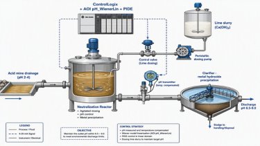
Control of pH Based on a Wiener Model
Studio 5000 solution for nonlinear pH control using a Wiener model and PIDE regulatory control.
Tags:
Hardware,
Software
Languages:
English,
Spanish,
Portuguese
Deploy Time: 30 Minutes
English
Spanish
Portuguese
Aerospace
Airports & Airlines
Automotive & Tire
Cement
Chemical
Entertainment
Fiber & Textiles
Food & Beverage
Household & Personal Care
Hydrogen
Infrastructure
Life Sciences
Marine
Metals
Mining
Mining, Metals & Cement
Oil & Gas
Power Generation
Print & Publishing
Pulp & Paper
Semiconductor
Water Wastewater
Warehouse & Fulfillment
Mass Transit
Renewable Energy
Manufacturing
Waste Management
Implementer
Software
Process Solutions
Sizing a PlantPAx system for applications with up to 10 Operator Workstations
Guide to size a PlantPAx system (up to 10 operator workstations) using IAB and PSE, ensuring validated architecture, correct components, and aligned cost/resource estimates.
What does this application do?
Sizing a PlantPAx system using Integrated Architecture Builder (IAB) and Process System Estimator (PSE) is essential to ensure technical accuracy and economic efficiency. IAB allows you to select and validate the correct control architecture components, ensuring compatibility and adequate performance, while PSE provides detailed cost and resource estimates, aligning the project with the process needs and budget. This integrated approach reduces risks of oversizing or failures, optimizes scalability, and ensures compliance with Rockwell Automation best practices, resulting in a robust, safe, and economically viable system.
General Characteristics
The proposed system consists of a CompactLogix controller dedicated to process applications, integrated with a set of I/O modules and smart drives, all connected through an EtherNet/IP industrial network structure). This architecture ensures precise and scalable control, reliable communication between devices, support for advanced automation strategies and integration with supervisory systems, offering high availability, flexibility for expansion, and compliance with process automation best practices.
Advantages
- Sizing through an updated tool
- Use of updated solutions focused on each discipline
- Assessment of possible challenges to be encountered
- Possibility of preparing complete studies related to the sized system
Limitations and Disadvantages - The IAB Software (Integrated Architecture Builder) needs to be updated to its latest version
Downloads
Please note: You will need to agree to the Terms & Conditions for each download.
Need Help?
If you need help with an application or have feedback from the Innovation Center, please contact us.
Is this application relevant to me?
This type of solution is advantageous for the user because it offers simplicity, reliability, and integration in a single package. With a CompactLogix controller, I/O, and drives connected on the network, the user obtains centralized control and standardized communication, reducing installation and maintenance complexity. In addition, the architecture is scalable and flexible, allowing future expansion without major investments, and ensures high availability and performance, resulting in greater operational efficiency, less downtime, and ease of integration with supervisory and management systems.
How can I make it work?
Requirements: products, tools, prior knowledge.
Hardware
- Standard computer or notebook
Software
- IAB (Integrated Architecture Builder), available on the Rockwell website for free download
Implementation Guide
Open IAB (Integrated Architecture Builder), and if necessary, perform the update of the program database.
If you have Internet access, you can update your IAB by clicking “Yes”.
sizing-a-plantpax-system-for-applications-with-up-to-10-operator-workstations_Picture1.png
To start our project, click on “Existing Project” and import the provided file “App Innovation Center”.
sizing-a-plantpax-system-for-applications-with-up-to-10-operator-workstations_Picture2.png
Select the application generated in Process System Estimator named “PlantPAx 10 OWS (Virt Lite)”.
sizing-a-plantpax-system-for-applications-with-up-to-10-operator-workstations_Picture3.png
Once the application is open, you can perform the configurations related to the remotes, drives, IED Protection Relays and Local Operation Stations, for each area of your system:
sizing-a-plantpax-system-for-applications-with-up-to-10-operator-workstations_Picture4.png
Configurations related to the IOs
sizing-a-plantpax-system-for-applications-with-up-to-10-operator-workstations_Picture5.png
Configurations related to the Drives
sizing-a-plantpax-system-for-applications-with-up-to-10-operator-workstations_Picture6.png
Configurations related to the IED relays
sizing-a-plantpax-system-for-applications-with-up-to-10-operator-workstations_Picture7.png
Configurations related to Local Operation
sizing-a-plantpax-system-for-applications-with-up-to-10-operator-workstations_Picture8.png
Once the items above are configured, it is possible to evaluate the Controller Status and thus have a broader view of the project as a whole. Once evaluated, simply finish and export the bill of materials.
sizing-a-plantpax-system-for-applications-with-up-to-10-operator-workstations_Picture9.png
Note: it is important to reinforce that PlantPAx is a Characterized Distributed Control System, therefore it is essential to adopt all practices, from sizing to system startup, always using the official Rockwell Automation manuals found through the link PlantPAx Distributed Control System | Rockwell Automation | US
sizing-a-plantpax-system-for-applications-with-up-to-10-operator-workstations_Picture1.png
sizing-a-plantpax-system-for-applications-with-up-to-10-operator-workstations_Picture2.png
sizing-a-plantpax-system-for-applications-with-up-to-10-operator-workstations_Picture3.png
sizing-a-plantpax-system-for-applications-with-up-to-10-operator-workstations_Picture4.png
sizing-a-plantpax-system-for-applications-with-up-to-10-operator-workstations_Picture5.png
sizing-a-plantpax-system-for-applications-with-up-to-10-operator-workstations_Picture6.png
sizing-a-plantpax-system-for-applications-with-up-to-10-operator-workstations_Picture7.png
sizing-a-plantpax-system-for-applications-with-up-to-10-operator-workstations_Picture8.png
sizing-a-plantpax-system-for-applications-with-up-to-10-operator-workstations_Picture9.png
Step 3: Lorem Ipsum
Sizing a PlantPAx system for applications with up to 10 Operator Workstations
Version 1.0 - June 2026

Sizing a PlantPAx system for applications with up to 10 Operator Workstations
Guide to size a PlantPAx system (up to 10 operator workstations) using IAB and PSE, ensuring validated architecture, correct components, and aligned cost/resource estimates.
Tags:
Software
Languages:
English,
Spanish,
Portuguese
Deploy Time: 30 Minutes
English
Spanish
Portuguese
Aerospace
Airports & Airlines
Automotive & Tire
Cement
Chemical
Entertainment
Fiber & Textiles
Food & Beverage
Household & Personal Care
Hydrogen
Infrastructure
Life Sciences
Marine
Metals
Mining
Mining, Metals & Cement
Oil & Gas
Power Generation
Print & Publishing
Pulp & Paper
Semiconductor
Water Wastewater
Warehouse & Fulfillment
Mass Transit
Renewable Energy
Manufacturing
Waste Management
Manager
Implementer
Software
Industrial Automation & Control
Industrial Networks
Consulting & Integration Services
How to Connect Your Plant or Machine to Azure Using FT‑Optix
Visualization and core integration application to connect your plant or machine directly to Microsoft Azure.
Limitations and Disadvantages - FT‑Optix-only application.
What does this application do?
Currently, automation projects and applications, whether for process industries or machine builders, are becoming increasingly connected to cloud computing, enabling these applications to send data for analysis and decision-making.
This getting-started guide describes the integration between FactoryTalk® Optix™ and Azure IoT Operations, tested on a fluid processing demonstration machine jointly developed by Rockwell Automation and Microsoft. This application concept can also be implemented by OEM machine builders.
The guide covers the architecture, installation, and configuration steps required for the integration. The architecture section includes a diagram illustrating the adaptive cloud approach, data plane, and management plane. The installation section provides detailed steps for setting up FactoryTalk Optix and Azure IoT Operations, including a shell script to automate the process. The configuration section explains how to configure FactoryTalk Optix and Azure IoT Operations, including creating applications, configuring OPC UA servers, and generating certificates.
General Characteristics
FactoryTalk Optix Studio is an integrated development environment (IDE) with a functional module framework for designing and building HMI (Human-Machine Interface) and Internet of Things (IoT) applications. FactoryTalk Optix Studio includes a library of predefined objects that support the modular design of graphical interfaces, features, and logical operations within an HMI application. Using C# language scripts, you can automate various actions during the design phase and add custom functionality to projects.
FactoryTalk Optix Studio is available as both a desktop- and web-based development environment used to build FactoryTalk Optix Applications and deploy them to client systems. The web-based FactoryTalk Optix Studio editor is accessed through FactoryTalk Hub.
You develop and build FactoryTalk Optix Applications in FactoryTalk Optix Studio. The compiled applications can be deployed to Windows® or Linux client systems, or to Rockwell Automation closed devices such as the OptixPanel or the Embedded Edge Compute Module.
Downloads
Please note: You will need to agree to the Terms & Conditions for each download.
Need Help?
If you need help with an application or have feedback from the Innovation Center, please contact us.
Architecture
The adaptive cloud approach being adopted by Rockwell Automation and Microsoft is shown in the diagram below.
The diagram below illustrates how the integration between FactoryTalk Optix and Azure IoT Operations can be achieved based on the fluid processing demonstration machine jointly developed by Rockwell Automation and Microsoft. This integration can be applied to any other scenario that requires infrastructure for data transfer and edge management.
The diagram is divided into three sections: the top section shows the vision for the adaptive cloud approach, the second section shows what has been achieved in the data plane through a functional proof of concept, and the third section shows what can be achieved with the management plane.
Advantages - Direct connection to the cloud – Microsoft Azure
Limitations and Disadvantages - FT‑Optix-only application.
Is this application relevant to me?
A ready-to-use application for integration with FT Optix and Azure. It is open source and can be easily implemented or used as a foundation for your project.
For controller connectivity, FT Optix supports integration with Logix controllers (Rockwell Automation) as well as third-party controllers.
See our available drivers: https://www.rockwellautomation.com/pt-pt/docs/factorytalk-optix/current/contents-ditamap/creating-projects/communication-driver/communication-drivers-overview.html
How can I make it work?
Requirements: products, tools, prior knowledge.
Hardware
- Intel Core i5 Standard Power processor (i5-8xxx)
- 8 GB of RAM memory
- 20 GB free hard disk space
The hardware requirements for FactoryTalk Optix applications may vary depending on the application and the type of device running the application.
Software Requirements for FactoryTalk Optix Applications - Windows 10 (x64), Windows 11 (x64), Windows Server 2016, Windows Server 2019, Windows Server 2022, or Ubuntu 22 (x64)
Software
- FactoryTalk Optix
- Download and install FactoryTalk Optix Studio and Runtime.
- Download Link: https://home.cloud.rockwellautomation.com/sign-in?returnTo=%2Fdashboard
- It can be downloaded from PCDC: https://compatibility.rockwellautomation.com/Pages/home.aspx
- Azure IoT Operations
- Install the Kubernetes cluster and Azure IoT Operations according to the instructions provided in: https://learn.microsoft.com/en-us/azure/iot-operations/deploy-iot-ops/overview-deploy
- Alternatively, refer to Appendix A – Automating Azure IoT Operations Installation for a shell script that automatically installs a Kubernetes cluster and deploys Azure IoT Operations on it. https://github.com/FactoryTalk-Optix/Optix_Sample_AzureIoTOperations?tab=readme-ov-file#appendix-a---automate-azure-iot-operations-install
ATTENTION: The script linked above was created and tested with the preview version and may require adaptation for later releases.
Prior Knowledge
- SO Windows
- FactoryTalk Optix Studio
Implementation Guide
Download our sample application from Download >> General_Files.zip
Optix_Sample_AzureIoTOperations-main
The sample FactoryTalk Optix application in this repository contains the key components required to publish data from a control system to Azure IoT Operations.
The sample application includes:
- A sample PLC program for Allen Bradley L8 ControlLogix
- EtherNet/IP communication driver
- Application certificate
- OPC UA Server
- Graphical User Interface (GUI)
- PLC data reading
- Manual tag writing (for use when no PLC is connected)
NOTE: The application certificate used by the application must be regenerated to match your computer name.
Alternatively, follow the steps below to manually create a FactoryTalk Optix application containing OPC UA data and expose it as an OPC UA Server for use with Azure IoT Operations.
- Use FactoryTalk Optix Studio to create a FactoryTalk Optix application.
- Add the communication driver(s) required to read data from the control system.
- Use the RAEtherNet/IP driver to connect to a Rockwell Automation controller.
- OPC UA is supported through the OPC UA object.
optix_comms_drivers.PNG
After the download, open the application:
optix_runtime_app.PNG
Use the Settings → Create Certificate menu to create an application certificate for the FactoryTalk Optix Server. This certificate will be used to authenticate the FactoryTalk Optix OPC UA Server with Azure IoT Operations.
optix_create_certificate.PNG
In the Project Folder pane, add an OPC UA Server.
- Set the Server certificate file and Server private key file properties to use the FactoryTalk Optix certificate.
- Use the Nodes to publish property to create a configuration that publishes a subset of nodes, or leave it blank to publish all nodes.
- Set the Endpoint URL property to use the computer name or IP address so that it is accessible from the AIO box.
- Set the Use node path in NodeIds property to True to use fully qualified tag names when configuring tags in AIO. Setting this property to True ensures that OPC UA tag names use the friendly format ns=<namespace>;s=Path.To.Node rather than requiring the node ID GUID to be specified.
opcua_server.PNG
Import the AIO certificates into the project's trusted store using the instructions provided in the FactoryTalk Optix Studio Help.
Azure IoT Operations
Import the FactoryTalk Optix certificate into the trusted store using the instructions provided in Configure OPC UA Certificates - Azure IoT Operations Preview | Microsoft Learn.
Open the Operations Experience site to configure assets and data flows.
https://iotoperations.azure.com/
On the Asset Endpoints page, create an asset endpoint profile that points to the FactoryTalk Optix OPC UA Server.
aio_asset_endpoints.PNG
On the Assets page, create an asset that uses the endpoint profile and configure the tag list.
aio_asset_tags.PNG
aio_assets.PNG
TIP: The node address for OPC UA tags can be viewed in FactoryTalk Optix Studio. Alternatively, you can use an OPC UA client such as UAExpert to browse the FactoryTalk Optix OPC UA Server and obtain the address configuration for the tags. The node ID of a tag must use the following format:
nsu=<Optix_Application_Name>;s=Path.To.Node
For example, if the Optix application is named aio_optix1 and a tag called Variable1 was created in the folder AIOTags, which is a child of the Model folder:
nsu=aio_optix1;s=aio_optix1.Model.AIOTags.Variable1
Automate Azure IoT operations:
The setupaio.sh shell script automates the installation of a Kubernetes cluster and deploys an Azure IoT Operations instance on the cluster.
- Assumptions:
- The script will create a single-node cluster.
- The script will use a specified user account for access.
Note - The script was created and tested with the Preview version and may require adaptation for later releases. This script is provided as-is, without warranty or support, and it is the user's responsibility to test and validate it before deploying it in a production environment. Copy the code into a file and name it setupaio.sh.
Caution - The file must be created directly in the Ubuntu environment to avoid formatting errors related to line-ending characters.
The code can be found at the following link: https://github.com/FactoryTalk-Optix/Optix_Sample_AzureIoTOperations/blob/main/setupaio.sh
Use the following command to execute the script and pass in the mandatory parameters: bash setupaio.sh -l <your_location> -g <your_resource_group> -c <your_cluster_name> -u <your_user_email>
Run the script again if an error is encountered during execution. In some cases, an error may occur when an object is newly created and immediately referenced, so rerunning the script can resolve the issue. However, you should document any errors and address them with an appropriate resolution to ensure the environment is configured correctly.
optix_comms_drivers.PNG
optix_runtime_app.PNG
optix_create_certificate.PNG
opcua_server.PNG
aio_asset_endpoints.PNG
aio_assets.PNG
aio_asset_tags.PNG
send-data-between-controllers-with-handshake-in-studio-5000_Step6-Image1
send-data-between-controllers-with-handshake-in-studio-5000_Step7-Image1
send-data-between-controllers-with-handshake-in-studio-5000_Step8-Image1
optix_comms_drivers.PNG
optix_runtime_app.PNG
optix_create_certificate.PNG
opcua_server.PNG
aio_asset_endpoints.PNG
aio_assets.PNG
aio_asset_tags.PNG
send-data-between-controllers-with-handshake-in-studio-5000_Step6-Image1
send-data-between-controllers-with-handshake-in-studio-5000_Step7-Image1
send-data-between-controllers-with-handshake-in-studio-5000_Step8-Image1
How to Connect Your Plant or Machine to Azure Using FT‑Optix
Version 2.0 - September 2026

How to Connect Your Plant or Machine to Azure Using FT‑Optix
Visualization and core integration application to connect your plant or machine directly to Microsoft Azure.
Tags:
Software
Languages:
English,
Spanish,
Portuguese
Deploy Time: 120 Minutes
English
Spanish
Portuguese
Aerospace
Automotive & Tire
Cement
Chemical
Entertainment
Fiber & Textiles
Food & Beverage
Household & Personal Care
Hydrogen
Infrastructure
Life Sciences
Marine
Metals
Mining
Mining, Metals & Cement
Oil & Gas
Power Generation
Print & Publishing
Pulp & Paper
Semiconductor
Water Wastewater
Warehouse & Fulfillment
Airports & Airlines
Mass Transit
Renewable Energy
Manufacturing
Waste Management
Implementer
Software
Hardware
Industrial Automation & Control
FactoryTalk Optix: Condition Monitoring Dashboards
FactoryTalk Optix dashboards for Condition-Based Maintenance (CBM) using Dynamix 1444.
Download
Please note: You will need to agree to the Terms & Conditions for each download.
Need Help?
If you need assistance with an application, subscription or have feedback about the Innovation Center, contact us.
What does this application do?
Used to visualize vibration and temperature (taken at the same measurement point) and to manage the corresponding alarms.
General Characteristics
This development includes the following:
- Program configuration in Studio 5000
- HMI screen setup in FactoryTalk Optix
Advantages:
- Provides an initial reference for condition monitoring developments of rotating machines.
- Enable monitoring of the system, even remotely.
Limitations/Disadvantages
- It is limited to acceleration and temperature readings acquired through the Dynamix 1444.
Is this application relevant to me?
If you need to implement a panel to monitor the vibration and temperature of rotating machines.
Application Areas - It can be applied in condition-based monitoring environments for rotating machines.
How can I make it work?
Requirements: products, tools, prior knowledge.
Hardware
- Any Logix Controller
- Any Optix Panel or PC
- Dynamix 1444
Software
- Studio 5000 (the program was developed in version 38)
- FactoryTalk Optix (application developed using version 1.6)
Knowledge
- Basic knowledge of programming and configuration in:
- Studio 5000
- Factorytalk Optix
- Vibration Analysis
Implementation Guide
Studio 5000 Program
1. Extract the programs:
factorytalk-optix-condition-monitoring-dashboards_16x9-optix_monitoreo_step1_image01.jpg
2. Open the Studio 5000 program
For testing this application, a CompactLogix 5380 was used.
factorytalk-optix-condition-monitoring-dashboards_16x9-optix_monitoreo_step1_image02.jpg
3. Configure the 1444 module
a) Add the 1444-DYN04-01RA module
b) Configure the module personality according to the specific needs of the application.
c) We will work with a dual accelerometer 1443-ACC-AT-T, but the procedure is similar for accelerometers that include temperature measurement from other brands.
factorytalk-optix-condition-monitoring-dashboards_16x9-optix_monitoreo_step1_image03.jpg
factorytalk-optix-condition-monitoring-dashboards_16x9-optix_monitoreo_step1_image04.jpg
factorytalk-optix-condition-monitoring-dashboards_16x9-optix_monitoreo_step1_image05.jpg
factorytalk-optix-condition-monitoring-dashboards_16x9-optix_monitoreo_step1_image06.jpg
4. We will configure the AOP according to a typical centrifugal pump application, using the application document 1444-AT001 as a reference for the case ‘Pumps – Horizontal Mount’
a) Connection b) Speed c) HW Configuration d) Filters |
e) Overall f) FFT g) Bands h) Temperature configuration |
factorytalk-optix-condition-monitoring-dashboards_16x9-optix_monitoreo_step1_image07.jpg
factorytalk-optix-condition-monitoring-dashboards_16x9-optix_monitoreo_step1_image08.jpg
factorytalk-optix-condition-monitoring-dashboards_16x9-optix_monitoreo_step1_image09.jpg
factorytalk-optix-condition-monitoring-dashboards_16x9-optix_monitoreo_step1_image10.jpg
factorytalk-optix-condition-monitoring-dashboards_16x9-optix_monitoreo_step1_image11.jpg
factorytalk-optix-condition-monitoring-dashboards_16x9-optix_monitoreo_step1_image12.jpg
factorytalk-optix-condition-monitoring-dashboards_16x9-optix_monitoreo_step1_image13.jpg
factorytalk-optix-condition-monitoring-dashboards_16x9-optix_monitoreo_step1_image14.jpg
5. We will configure the alarms within the 1444 module.
factorytalk-optix-condition-monitoring-dashboards_16x9-optix_monitoreo_step1_image15.jpg
factorytalk-optix-condition-monitoring-dashboards_16x9-optix_monitoreo_step1_image16.jpg
factorytalk-optix-condition-monitoring-dashboards_16x9-optix_monitoreo_step1_image17.jpg
FactoryTalk Optix Development
1. Open the folder named ‘CM_Optix_rev1’ that was downloaded.
factorytalk-optix-condition-monitoring-dashboards_16x9-optix_monitoreo_step2_image01.jpg
2. Inside the folder, open the FactoryTalk Optix file: CM_Optix_rev1.optix.
factorytalk-optix-condition-monitoring-dashboards_16x9-optix_monitoreo_step2_image02.jpg
factorytalk-optix-condition-monitoring-dashboards_16x9-optix_monitoreo_step2_image03.jpg
3. Configure the EtherNet/IP communication
factorytalk-optix-condition-monitoring-dashboards_16x9-optix_monitoreo_step2_image04.jpg
4. Import the tags from the Studio 5000 program that are necessary to display whether the equipment is operating and for how long.
factorytalk-optix-condition-monitoring-dashboards_16x9-optix_monitoreo_step2_image05.jpg
5. Review the hierarchy where the elements used to create the screen are displayed.
factorytalk-optix-condition-monitoring-dashboards_16x9-optix_monitoreo_step2_image06.jpg
6. Verify the screens and modify them according to your specific requirements.
factorytalk-optix-condition-monitoring-dashboards_16x9-optix_monitoreo_step2_image07.jpg
7. Modify the DataLoggers with the changes you want to apply.
factorytalk-optix-condition-monitoring-dashboards_16x9-optix_monitoreo_step2_image08.jpg
factorytalk-optix-condition-monitoring-dashboards_16x9-optix_monitoreo_step1_image01.jpg
factorytalk-optix-condition-monitoring-dashboards_16x9-optix_monitoreo_step1_image02.jpg
factorytalk-optix-condition-monitoring-dashboards_16x9-optix_monitoreo_step1_image03.jpg
factorytalk-optix-condition-monitoring-dashboards_16x9-optix_monitoreo_step1_image04.jpg
factorytalk-optix-condition-monitoring-dashboards_16x9-optix_monitoreo_step1_image05.jpg
factorytalk-optix-condition-monitoring-dashboards_16x9-optix_monitoreo_step1_image06.jpg
factorytalk-optix-condition-monitoring-dashboards_16x9-optix_monitoreo_step1_image07.jpg
factorytalk-optix-condition-monitoring-dashboards_16x9-optix_monitoreo_step1_image08.jpg
factorytalk-optix-condition-monitoring-dashboards_16x9-optix_monitoreo_step1_image09.jpg
factorytalk-optix-condition-monitoring-dashboards_16x9-optix_monitoreo_step1_image10.jpg
factorytalk-optix-condition-monitoring-dashboards_16x9-optix_monitoreo_step1_image13.jpg
factorytalk-optix-condition-monitoring-dashboards_16x9-optix_monitoreo_step1_image14.jpg
factorytalk-optix-condition-monitoring-dashboards_16x9-optix_monitoreo_step1_image11.jpg
factorytalk-optix-condition-monitoring-dashboards_16x9-optix_monitoreo_step1_image12.jpg
factorytalk-optix-condition-monitoring-dashboards_16x9-optix_monitoreo_step1_image15.jpg
factorytalk-optix-condition-monitoring-dashboards_16x9-optix_monitoreo_step1_image16.jpg
factorytalk-optix-condition-monitoring-dashboards_16x9-optix_monitoreo_step1_image17.jpg
factorytalk-optix-condition-monitoring-dashboards_16x9-optix_monitoreo_step2_image01.jpg
factorytalk-optix-condition-monitoring-dashboards_16x9-optix_monitoreo_step2_image02.jpg
factorytalk-optix-condition-monitoring-dashboards_16x9-optix_monitoreo_step2_image03.jpg
factorytalk-optix-condition-monitoring-dashboards_16x9-optix_monitoreo_step2_image04.jpg
factorytalk-optix-condition-monitoring-dashboards_16x9-optix_monitoreo_step2_image05.jpg
factorytalk-optix-condition-monitoring-dashboards_16x9-optix_monitoreo_step2_image06.jpg
factorytalk-optix-condition-monitoring-dashboards_16x9-optix_monitoreo_step2_image07.jpg
factorytalk-optix-condition-monitoring-dashboards_16x9-optix_monitoreo_step2_image08.jpg
FactoryTalk Optix: Condition Monitoring Dashboards
Version 1.0 - January 2026

FactoryTalk Optix: Condition Monitoring Dashboards
FactoryTalk Optix dashboards for Condition-Based Maintenance (CBM) using Dynamix 1444.
Tags:
Software,
Hardware
Languages:
English,
Spanish,
Portuguese
Deploy Time: 30 Minutes
Spanish
English
Portuguese
Chemical
Implementer
Software
Industrial Automation & Control
Heat Balance Using Steam Table
The desired management of the amount of thermal energy in the plant, every day, becomes more relevant in the process operation.
The desired management of the amount of thermal energy in the plant, every day, becomes more relevant in the operation, given that it impacts on the variable operating costs, as well as the carbon footprint of the product and the company. For this reason, any type of industry, such as CPG, chemical, Oil and Gas, Pharmaceuticals, among others, has become a key KPI in production, which is why companies are interested in knowing the specific amount of energy that their raw materials use at the right time, providing this information to the person. appropriate, to make appropriate decisions.
The application presented has the calculation of the material balance for three types of energy sources, named as follows:
- LP, Low Pressure,
- MP, Medium Pressure,
- HP, High Pressure,
And each of them is evaluated against a flow of:
1000 Kg/h, 5000 Kg/h and 10,000 Kg/h, to have an instantaneous energy balance.
What does this application do?
The application of configuring an energy balance for specific operating conditions, covering low pressure, medium pressure and high pressure regions, which are described above. Studio5000 is used, the PlantPAx version 4.1 libraries for the Vapor libraries, the FTLogix Echo, for configuration and simulation, in the amounts of energy and flows, so the user can modify the variables mentioned below, in order to explore its configuration in more detail:
- Temperature Variation
- Pressure Variation
- Amount of Energy in real time
- Region of thermodynamics where T and P are located, with respect to their Tsat and Psat the water vapor
General characteristics
The configuration of an energy balance in low, medium and high pressure conditions, which offers the following characteristics:
- Adjustable steam flow reference.
- Use of the Steam tables in Low, Medium and High pressure.
Advantages
Shows the integration of tools from the PlantPAx process libraries in the configuration of process equipment.
- Demonstrates the use of Studio 5000 in dynamic modeling of energy balance calculations.
- Allows you to relate the Studio 5000 with simulation tools such as the FTLogix Echo.
- Speeds up configuration time for low, medium, and high pressure energy balances using steam libraries.
- Exhibits scalability and repeatability to adapt to various industrial environments.
- Allow agile and precise modifications according to changing needs.
- Optimize performance in terms of efficiency and productivity.
Download
Please note: You will need to agree to the Terms & Conditions for each download.
Need Help?
If you need help with an application or have feedback from the Innovation Center, please contact us.
Is this application relevant to me?
Benefits - The user of the configuration will be able to find a ready-made configuration of an energy balance, with the capacity for dynamic modeling of its operation, and manipulate both the fluids and the amount of total energy of Low, Medium and High Pressure vapor.
How can I make it work?
Requirements: products, tools, prior knowledge.
- Hardware
- ControlLogix
- CompactLogix
- Software
- Studio5000 (V35)
- FT Logix Echo
- PlantPAx Libraries 5.2
- PlantPAx Libraries 4.2 (Steam Table)
- Background knowledge
- Knoowledge of Studio 5000.
- FTLogixEcho.
- PlantPAX Process Libraries.
- Thermodynamics.
Links of Interest (internal or external)
- https://compatibility.rockwellautomation.com/Pages/MultiProductDownload.aspx?Keyword=Free&crumb=112
- PlantPAx Display and Library Guidelines
- Rockwell Automation Library of Steam Table Instructions Version 4.0
Implementation Guide
Setting selection.
heat-balance-using-steam-table_Image1_Studio_5000_ACD
FTLogixEcho Configuration.
heat-balance-using-steam-table_Image2_FTLogixEcho_Connection
Initial parameter settings.
heat-balance-using-steam-table_Add_On_Instruction
Pressure Transmitter Simulation Setup.
heat-balance-using-steam-table_Image3_Studio5000_LP_Page_1_Pressure_Simulation
Temperature transmitter simulation setup.
heat-balance-using-steam-table_Studio5000_LP_Page_2_Temperature_Simulation
Enthalpy Calculation.
heat-balance-using-steam-table_Image5_Studio5000_LP_Page_3_Entalphy_Calculation
Calculation of the Quantity of Energy.
heat-balance-using-steam-table_Image5_Studio5000_LP_Page_4_Energy_Calculation
Pressure Transmitter Simulation Setup.
heat-balance-using-steam-table_Studio5000_MP_Page_1_Pressure_Simulation
Temperature transmitter simulation setup.
heat-balance-using-steam-table_Studio5000_MP_Page_2_Temperature_Simulation
Enthalpy Calculation.
heat-balance-using-steam-table_Studio5000_MP_Page_3_Entalphy_Calculation
Calculation of the Quantity of Energy.
heat-balance-using-steam-table_Studio5000_MP_Page_4_Energy_Calculation
Pressure Transmitter Simulation Setup.
heat-balance-using-steam-table_Studio5000_HP_Page_1_Pressure_Simulation
Temperature transmitter simulation setup.
heat-balance-using-steam-table_Studio5000_HP_Page_1_Temperature_Simulation
Enthalpy Calculation..
heat-balance-using-steam-table_Studio5000_HP_Page_3_Entalphy_Calculation
Calculation of the Quantity of Energy.
heat-balance-using-steam-table_Studio5000_HP_Page_4_Energy_Calculation
heat-balance-using-steam-table_Image1_Studio_5000_ACD
heat-balance-using-steam-table_Image2_FTLogixEcho_Connection
heat-balance-using-steam-table_Add_On_Instruction
heat-balance-using-steam-table_Image3_Studio5000_LP_Page_1_Pressure_Simulation
heat-balance-using-steam-table_Studio5000_LP_Page_2_Temperature_Simulation
heat-balance-using-steam-table_Image5_Studio5000_LP_Page_3_Entalphy_Calculation
heat-balance-using-steam-table_Image5_Studio5000_LP_Page_4_Energy_Calculation
heat-balance-using-steam-table_Studio5000_MP_Page_1_Pressure_Simulation
heat-balance-using-steam-table_Studio5000_MP_Page_2_Temperature_Simulation
heat-balance-using-steam-table_Studio5000_MP_Page_3_Entalphy_Calculation
heat-balance-using-steam-table_Studio5000_MP_Page_4_Energy_Calculation
heat-balance-using-steam-table_Studio5000_HP_Page_1_Pressure_Simulation
heat-balance-using-steam-table_Studio5000_HP_Page_1_Temperature_Simulation
heat-balance-using-steam-table_Studio5000_HP_Page_3_Entalphy_Calculation
heat-balance-using-steam-table_Studio5000_HP_Page_4_Energy_Calculation
Heat Balance Using Steam Table
Version 1.2 - June 2026

Heat Balance Using Steam Table
The desired management of the amount of thermal energy in the plant, every day, becomes more relevant in the process operation.
Tags:
Software
Languages:
Spanish,
English,
Portuguese
Deploy Time: 60 Minutes
English
Spanish
Portuguese
Oil & Gas
Implementer
Software
Industrial Automation & Control
Oil & Gas Well Emulation Using Logix AI
Use Logix AI to integrate synthetic Oil & Gas well data, to develop representative models that can be deployed in Studio 5000 and Logix Echo.
How can I make it work?
Download
Please note: You will need to agree to the Terms & Conditions for each download.
Need Help?
If you need help with an application or have feedback from the Innovation Center, please contact us.
Artificial Intelligence has become a key enabler in today’s Oil & Gas industry, particularly under market conditions characterized by volatile oil prices and increasing pressure to reduce operating costs and energy consumption. AI-based solutions support both onshore and offshore operations by optimizing energy efficiency, improving throughput in surface processing equipment and wells, and enhancing production quality through better control of parameters such as Basic Sediment and Water (BSW).
In this context, the development of predictive models for inferential sensors is a strategic approach to improve real-time monitoring and decision-making. These models enable the estimation of critical production and reservoir variables—including oil volume, total liquid rate, gas volume, water cut, dynamic fluid level, and reservoir pressure—without relying exclusively on physical sensors, thereby reducing CAPEX, OPEX, and operational risk while maintaining production reliability.
What does this application do?
The emulation of the Oil Volume, in a Oil & Gas well is very important because it will be used to virtual commissioning and performance representation of the well, and scenarios like a sand box for operator training. The implementation use the model of a Logix AI for the oil volume representation, FT Studio 5000 for the emulation and FT Logix Echo to represent the controller.
General Characteristics
An emulation of an Oil & Gas well, with a focus on Oil Volume, offers the following characteristics:
- The identification of VOI is the Oil Volume in [m3/day]
- The selection of Input 1 is Volume of liquid [m3/day]
- The selection of Input 2 is Gas Volume [m3/day]
- The selection of Input 3 is Gas volume Water volume [m3/day]
Advantages
- Shows the use of Logix AI.
- Speeds up the virtual commissioning and performance of the Oil Volume in oil and gas wells.
- Exhibits scalability and repeatability to adapt to various industrial environments.
- Allow agile and precise modifications according to changing needs.
- Optimize performance in terms of efficiency and productivity.
Is this application relevant to me?
The Oil Volume prediction using Logix AI is util, because will be use with to emulate a virtual commissioning and Oil Volume performance.
How can I make it work?Requirements: products, tools, prior knowledge.
Hardware
- 1756-L85EP
Software
- Studio 5000 - Version 37
- FactoryTalk Logix Echo - Version 3.00.00
- FT Logix AI FactoryTalk® Analytics LogixAI ®
Previous Knowledge:
- Products: Logix AI , Studio 5000 and LogixEcho
- Tools: Studio 5000, FT LogixEcho and FT Logix AI
Links of Interest (internal or external)
- https://www.rockwellautomation.com/en-us/products/software/factorytalk/operationsuite/analytics-logixai.html
- https://www.rockwellautomation.com/en-us/products/software/factorytalk/designsuite/studio-5000/studio-5000-logix-designer.html
- https://www.rockwellautomation.com/en-us/products/software/factorytalk/designsuite/logix-echo.html
- https://www.rockwellautomation.com/en-us/industries/oil-gas.html%20.html
Implementation Guide
Review the historical synthetic data a .xlm file
oil-gas-well-emulation-using-logix-ai_1_Historical_Synthetic_Data_Oil_and_Gas_Well.png
Open the Logix AI portal.
oil-gas-well-emulation-using-logix-ai_2_Open_Logix_AI.png
Select “Conduct Experiment”, highlighted in blue
oil-gas-well-emulation-using-logix-ai_3_Create_an_Experimental_Model_ highlighted in blue.png
Select “template”, highlighted in blue.
oil-gas-well-emulation-using-logix-ai_4_template_highlighted_in_blue.png
Review the file “template.csv”.
oil-gas-well-emulation-using-logix-ai_5_template_csv_file.png
Take the data from de Historical_Sintetic_Data_Oil_&_Gas_Well and replace in template file the changes done, will be like this:
oil-gas-well-emulation-using-logix-ai_6_6_ data_from_de_Historical_Sintetic_Data_Oil_and_Gas_Well.png
Save the File, like “Oil_Gas_Well_Logix_AI”.
oil-gas-well-emulation-using-logix-ai_6_6_ data_from_de_Historical_Sintetic_Data_Oil_and_Gas_Well.png
Select the file CHOOSE, the Logix AI platform will be look like, this:
oil-gas-well-emulation-using-logix-ai_8_ Select the file CHOOSE, the Logix AI platform will be look like this.png
Name the file “Oil_Gas_Well_Logix_AI” and select “Begin Experiment” highlighted in blue.
oil-gas-well-emulation-using-logix-ai_9 Begin Experiment.png
The Logix AI Experiment| Oil_Gas_Well_Logix_AI, will be look like this:
oil-gas-well-emulation-using-logix-ai_10_The Logix AI Experiment.png
Information
oil-gas-well-emulation-using-logix-ai_11_Information_Contributing.png
Information
oil-gas-well-emulation-using-logix-ai_12_Information_Not_Contributing.png
Calculation view
oil-gas-well-emulation-using-logix-ai_13_Calculation_View.png
oil-gas-well-emulation-using-logix-ai_1_Historical_Synthetic_Data_Oil_and_Gas_Well.png
oil-gas-well-emulation-using-logix-ai_2_Open_Logix_AI.png
oil-gas-well-emulation-using-logix-ai_3_Create_an_Experimental_Model_ highlighted in blue.png
oil-gas-well-emulation-using-logix-ai_4_template_highlighted_in_blue.png
oil-gas-well-emulation-using-logix-ai_5_template_csv_file.png
oil-gas-well-emulation-using-logix-ai_6_6_ data_from_de_Historical_Sintetic_Data_Oil_and_Gas_Well.png
oil-gas-well-emulation-using-logix-ai_7_ Oil_Gas_Well_Logix_AI.png
oil-gas-well-emulation-using-logix-ai_8_ Select the file CHOOSE, the Logix AI platform will be look like this.png
oil-gas-well-emulation-using-logix-ai_9 Begin Experiment.png
oil-gas-well-emulation-using-logix-ai_10_The Logix AI Experiment.png
oil-gas-well-emulation-using-logix-ai_11_Information_Contributing.png
oil-gas-well-emulation-using-logix-ai_12_Information_Not_Contributing.png
oil-gas-well-emulation-using-logix-ai_13_Calculation_View.png
Oil Gas Well Emulation Using Logix AI
Version 1.0 - May 2026

Oil & Gas Well Emulation Using Logix AI
Use Logix AI to integrate synthetic Oil & Gas well data, to develop representative models that can be deployed in Studio 5000 and Logix Echo.
Tags:
Software
Languages:
English,
Spanish,
Portuguese
Deploy Time: 60 Minutes
Spanish
English
Portuguese
Food & Beverage
Implementer
Software
Hardware
Machine & Equipment Builders
Rotary Knife
A functional example of applying libraries to configure a rotary blade.
Downloads
Please note: You will need to agree to the Terms & Conditions for each download.
Need Help?
If you need help with an application or have feedback from the Innovation Center, please contact us.
What does this application do?
This application serves as an example of how to use the raM_Tec_RotaryKnife library.
This AOI calculates four cam profiles for the rotary knife:
- Connection cam for acceleration from a stationary position. Typically from the initial axis position after homing or when there is no product/bag in production.
- Cyclic cam for continuous motion: one cut per product length.
- Disconnection cam for deceleration when stopping the knife without stopping the master axis.
- Dwell cam to keep the slave axis stopped for one product length.
When to Use: When a rotary knife cam profile is required for an axis.
When NOT to use: Not applicable (NA).
Functional Description
The cam calculation instruction generates profiles to synchronize the knife speed with the conveyor while they are in contact.
During the cyclic operation of a rotary knife, there is a synchronized portion and a compensation portion (see image below). The synchronized portion ensures that the knife and conveyor speeds are equal, while the compensation motion allows cut lengths to be shorter or longer than the circumference of the knife roll by accelerating or decelerating.
Compensation Motion (or Adjustment Motion):
- Motion of the knife where there is no contact between the knife and the conveyor (non-synchronized speeds).
- There are two possible interpolation profiles for the compensation motion:
- The interpolation priority is minimum energy usage and maximum speed; this may result in a non-continuous acceleration profile, even though the velocity and position profiles are continuous.
- The interpolation priority is motion smoothness (continuous position, velocity, and acceleration profiles); this may result in a higher maximum speed and may cause the knife to reverse direction for parameters that would not reverse when the maximum-speed/minimum-energy mode is selected.
Synchronized Motion:
- Motion of the knife where the knife and the conveyor are in contact (synchronized speeds).
- There are two possible profiles for synchronized motion:
- Linear Profile: Calculates the angular velocity of the knife to match the linear speed of the conveyor.
- Arcsine Compensation: Calculates the linear component of the angular velocity at each synchronization point to maintain exactly the same linear speed between the knife and the conveyor.
The Rotary Knife instruction generates four Cam Profiles (CAM) based on user-configurable inputs.
- Connection Cam:
- Use this cam profile when the master is in motion and the knife is stopped. The connection profile accelerates the knife from zero velocity to the synchronization speed, with a defined distance between the master and the slave, minimizing mechanical stress. The connection cam starts at the initial knife position and ends at the beginning of the synchronization distance. The distance of the connection cam plus the distance of the disconnection cam results in a complete cycle (cyclic cam distance). This applies to both master and slave distances.
- Cyclic Cam:
- Use this cam profile as the continuous knife cycle (one product). It contains synchronized motion (defined by Set_CutAngle in degrees) and compensation motion (defined by Set_ProductLength and Set_KnivesNumb).
- Disconnection Cam:
- Use this cam profile when it is necessary to command the knife to stop while the master continues moving. The disconnection profile decelerates the knife to zero velocity with a defined distance between the master and the slave, minimizing mechanical stress. The disconnection cam contains the synchronization profile and the motion profile from synchronization speed down to zero, considering the defined distance between the master and the slave. The distance of the connection cam plus the distance of the disconnection cam results in a complete cycle (cyclic cam distance). This applies to both master and slave distances.
- Dwell Cam:
- Use this cam profile to keep the slave axis stopped for a master distance (Set_ProductLength).
- Set_CutAngle
Cutting angle at which the master and slave move synchronously; the value is in degrees (as the entire slave must also be scaled in degrees). This value defines the distance the master must travel (X to V).
- Set_KnivesNumb
Number of knives. The number of knives defines the full cycle distance (for example, 1 knife = 360 degrees, 2 knives = 180 degrees, 3 knives = 120 degrees, etc.).
- Set_KnifeRadius
Knife radius. The radius units must match the master units (therefore, if master distances are in mm, it must be defined in mm; if in inches, the diameter must be in inches).
- Set_ProductLength
Master distance between two cuts (Y to W), defined in master units.
- Set_KnifeStartDist
Distance (A to C, in degrees) from the slave’s initial position to the first cut (i.e., after homing or dwell). The distance is defined up to the cutting position, which remains constant and independent of changes in the cutting angle (half of the cutting distance is automatically subtracted within the AOI when calculating the connection cam, since this cam does not include the synchronization motion, distance from A to B).
- Set_FilmStartDist
Master distance (U to W in master units) for the connection cam. This is the material distance to the next cutting position when starting after homing or exiting dwell (typically half the product length).
- Set_KnifeStopDist
Slave distance from the cutting position back to the initial position (C to A; the cam itself corresponds to a longer half synchronization to reach the initial position, since it contains the entire synchronization profile).
- Set_FilmStopDist
Master distance for the disconnection cam from the cutting position back to the initial position (i.e., half the product length).
- Cfg_ArcSinComp
Defines the velocity profile of the synchronized motion. If set to 0, the velocity profile is linear and the velocity Vmaster matches the velocity Vknife. If set to 1, the velocity Vmaster matches the projection of Vknife in the direction of Vmaster (VknifeX), for more precise synchronization.
- Cfg_CompMode
Defines the interpolation of the compensation motion.
If set to 0 (default), the interpolation prioritizes minimum energy usage and maximum speed; this may result in a non-continuous acceleration profile (while velocity and position profiles remain continuous).
If set to 1, the interpolation prioritizes smooth motion (continuous position, velocity, and acceleration profiles); this may result in higher maximum speed and may cause the knife to reverse direction under conditions where it would not reverse in mode 0.
- Cfg_KnifeReversal
Enables error checking for a cam to detect if the calculated cam profile includes a segment where the knife reverses direction (this may occur with improper combinations of input parameters, such as high cutting speed with long product length). When this error check is enabled and the error bit is active, the cam profiles will not be calculated.
How can I make it work?
Requirements: products, tools, prior knowledge.
Hardware
- CompactLogix 5380
- Kit Kinetix 5500
Software
- Studio 5000 - Version 35
Relevant links (internal or external)
- Download the libraries on the following link: https://compatibility.rockwellautomation.com/Pages/MultiProductFindDownloads.aspx?crumb=112&mode=3&refSoft=1&versions=56336
Implementation Guide
Open the Rotary Knife .ACD file and, in the controller properties, change the controller to match the available hardware.
rotary-knife_Step1.png
Modify the drive and the servo motor according to what is connected.
rotary-knife_Step2.png
Download the program to the controller and go online with it.
rotary-knife_Step3.png
4.1 - Enter the routine indicated in the image above:
rotary-knife_Step4-1.png
4.2 - In the Cmd_Reset contact, right-click and select Toggle Bit. With this instruction, you will initialize the servo motor, reset faults, and execute the Home routine.
rotary-knife_Step4-2.png
5.1 - Now go to the Ram_LD_RotaryKnife routine and configure the AOI according to your requirements.
rotary-knife_Step5-1.png
This is an example of how to configure a cam for a rotary knife in the Add-On Instruction (AOI).
5.2 - After homing, the knife is positioned 180 degrees away from the cutting position, and the film position is 200 units away from the first cut.
- There is only one knife in the jaws.
- The knife radius in the jaws is 50 mm.
- After homing, the knife position is 180 degrees from the cutting position.
- After homing, the film position is at the center of the product.
- The cutting angle is 60 degrees.
- The product length is 400 mm.
- When the knife stops, it is intended to stop exactly at the same position as after homing (so that it can start using the connection cam when there is no product/bag in operation).
rotary-knife_Step5-2.png
6.1 - Now go to the CM02_Production routine.
rotary-knife_Step6-1.png
6.2 - In this routine, you can start and stop the servo motor using the Toggle Bit function explained in step 4.
The servo motor will start using the profile defined in the previous step.
rotary-knife_Step6-2.png
rotary-knife_Step1.png
rotary-knife_Step2.png
rotary-knife_Step3.png
rotary-knife_Step4-1.png
rotary-knife_Step4-2.png
rotary-knife_Step5-1.png
rotary-knife_Step5-2.png
rotary-knife_Step6-1.png
rotary-knife_Step6-2.png
Rotary Knife
Version 1.1 - May 2026

Rotary Knife
A functional example of applying libraries to configure a rotary blade.
Tags:
Software,
Hardware
Languages:
Spanish,
English,
Portuguese
Deploy Time: 30 Minutes
English
Spanish
Portuguese
Aerospace
Airports & Airlines
Automotive & Tire
Cement
Chemical
Entertainment
Fiber & Textiles
Food & Beverage
Household & Personal Care
Hydrogen
Infrastructure
Life Sciences
Marine
Metals
Mining
Mining, Metals & Cement
Oil & Gas
Power Generation
Print & Publishing
Pulp & Paper
Semiconductor
Water Wastewater
Warehouse & Fulfillment
Mass Transit
Renewable Energy
Manufacturing
Waste Management
Implementer
Software
Software Evolution
Phase Correction in Cutting for Horizontal Balers
Rotary Knife Synchronization and Flying Cutting through phase correction using MAPC and MAR instructions for Kinetix 5000 Servo Drives.
What does this application do?
This is a simplified application for phase correction in cutting horizontal balers machines using an electronic cam. This application can be especially useful on horizontal packaging machines or some other type of cutting-on-the-fly machines.
General Features
This application uses a virtual axis as a master so the correction movements between the axes InFeed and Knife become independent from each other.
Advangages
- Simplified code
- Easy to implementación
- Implementation time reduction
- Cost reduction
- Operation efficiency
- Flexibitlity and scalability
Downloads
Please note: You will need to agree to the Terms & Conditions for each download.
Need Help?
If you need help with an application or have feedback from the Innovation Center, please contact us.
Is this application relevant to me?
This application can be used in cutting-on-the-fly machines, horizontal packaging, or any other type of application where an electronic cam with position correction is required. The application can be used as a complement to some existing code libraries.
How can I make it work?
Requirements: products, tools, prior knowledge.
Hardware
- Logix 5000 processor: ControlLogix and CompactLogix with Motion Control capabilities
- CIP Motion ServoDrives: Kinetix 5300/5500/5700
Software
- Studio 5000 – Logix Designer (V35.0→)
Prior Knowledge
- Intermediate to advanced knowledge on Studio 5000 Logix Designer
- Motion Control knowledge
Implementation Guide
Generate the appropriate cam profile for the application. The following images show an example of a cam that performs a dwell moment as well as a linear velocity step in the middle of the curve. This is done within the “Cam Profile” of the MAPC instruction.
In the CAM profile, identify the point where the blade would be in contact with the material (see red arrow in the image). Typically the linear speed stage is where the cutting moment takes place.
In the “MAPC” Electronic Cam instruction adjust the “Cam Position” parameter so that the cut-off point matches the appropriate cam curve response.
Once we have made the adjustments for both Master” and Cam Lock Positions, we can now set up the Knife Phase Correction routine.
For this a “Motion Arm Registratio” instruction is used to record the knife position at the time of detection of the Registration Mark.
In this instruction the registration mark detection window can be adjusted if it is necessary to discriminate detections outside the appropriate position range.
Continuing in the same routine “Knife_Phase_Correction”, we have the code to obtain the Correction Error through Set/Get System Value instructions; once this value is calculated, the correction is performed through an Incremental Movement.
phase-correction-in-cutting-horizontal-balers-machines_Imagen1
phase-correction-in-cutting-horizontal-balers-machines_Imagen2
phase-correction-in-cutting-horizontal-balers-machines_Imagen3
phase-correction-in-cutting-horizontal-balers-machines_Imagen4
phase-correction-in-cutting-horizontal-balers-machines_Imagen5
phase-correction-in-cutting-horizontal-balers-machines_Imagen6
phase-correction-in-cutting-horizontal-balers-machines_Imagen7
Phase Correction in Cutting for Horizontal Balers
Version 2.0 - September 2026

Phase Correction in Cutting for Horizontal Balers
Rotary Knife Synchronization and Flying Cutting through phase correction using MAPC and MAR instructions for Kinetix 5000 Servo Drives.
Tags:
Software
Languages:
English,
Spanish,
Portuguese
Deploy Time: 45 Minutes
English
Spanish
Portuguese
Aerospace
Airports & Airlines
Automotive & Tire
Cement
Chemical
Entertainment
Fiber & Textiles
Food & Beverage
Household & Personal Care
Hydrogen
Infrastructure
Life Sciences
Marine
Metals
Mining
Mining, Metals & Cement
Oil & Gas
Power Generation
Print & Publishing
Pulp & Paper
Semiconductor
Water Wastewater
Warehouse & Fulfillment
Mass Transit
Renewable Energy
Manufacturing
Waste Management
Implementer
Manager
Software
Industrial Automation & Control
Industrial Networks
Consulting & Integration Services
Connect Automation with IT Systems using FT-Optix and REST API
Connecting and integrating automation with IT systems, MES, SAP, CRM, and microservices using FT-Optix and REST API technology.
What does this application do?
REST API (Representational State Transfer Application Programming Interface) is a style of architecture for building web services. It defines a set of principles for communication between systems using standard web protocols, such as HTTP, allowing a flexible integration and connection between different architectures and microservices, being a very widespread technology technology technology technology information and microservices information and microservices is a technology that is widely used in the information technology system.
API stands for Application Programming Interface. In the context of APIs, the word Application refers to any software with a distinct function. The interface can be thought of as a service contract between two applications. This contract defines how the two communicate using requests and responses. The documentation for their respective APIs contains information on how developers should structure these requests and responses.
In this application note we present how FT-Optix with RESTAPI, allows machine, process and end customer manufacturers to interact with IT, SAP, MES systems and specific software using REST technology. This demo shows how to execute the call to a remote RestAPI server and process the response to show an interactive 3D model of the returned object
Download
Please note: You will need to agree to the Terms & Conditions for each download.
Need Help?
If you need help with an application or have feedback from the Innovation Center, please contact us.
General Characteristics
REST-API:
- Client-Server: Separation between client (frontend) and server (backend).
- Stateless: Each request is independent, meaning it does not maintain state on the server.
- Cacheable: Supports caching to improve performance.
- Uniform Interface: Utilizes well-defined HTTP methods, such as
- GET → Fetch Data
- POST → Create new features
- PUT → Update Existing Features
- DELETE → Remove Features
- Resource Impersonation: Data can be returned in formats such as JSON or XML.
Advantages
- Ease of Integration: Allows different systems to communicate in a simple way.
- Scalability: Being stateless, it facilitates the scalability of the system.
- Compatibility: It can be consumed by several clients (web, mobile, IoT).
- Simplicity: Uses well-known web standards such as HTTP and JSON, making it accessible to developers.
Limitations And Disadvantages - For FT-Optix up to the present version (1.5.2) only JSON format is accepted.
Is this application relevant to me?
Ready-to-integrate application with FT-Optix using REST-API, open source, and can be easily implemented or used as a basis in your project.
For connection to controllers, FT-Optix allows integration (communication driver) with Logix controllers (Rockwell Automation) or third-party controllers.
See our available drivers: https://www.rockwellautomation.com/pt-pt/docs/factorytalk-optix/current/contents-ditamap/creating-projects/communication-driver/communication-drivers-overview.html
How can I make it work?
Requirements: products, tools, prior knowledge.
Hardware
- Intel Core i5 Standard Power processor (i5-8xxx)
- 8 GB of RAM memory
- 20 GB free hard disk space
The hardware requirements for FactoryTalk Optix applications may vary depending on the application and the type of device running the application.
Software
- FactoryTalk Optix
- Download and install FactoryTalk, Optix Studio, and Runtime.
- Download Link: https://home.cloud.rockwellautomation.com/sign-in?returnTo=%2Fdashboard
- The PCDC can be downloaded: https://compatibility.rockwellautomation.com/Pages/home.aspx
Prior Knowledge
- Windows OS
- FactoryTalk Optix Studio
- Knowledge of REST-API technology
Implementation Guide
Download the app from Downloads/GeneralFiles.zip
Sample application uses REST-API from the https://restful-api.dev/rest-fundamentals site. A website containing server for demonstration projects and testing systems.
Open the application in FT-Optix Studio.
Automatically convert application if you have a newer version of FT-Optix.
connect-automation-with-it-systems-using-ft-optix-and-rest-api_Image2
- Run application and check operation
- Click the menu: GET List of All Objects, then click the GET button
Via REST-API, the command executes a script that requests (GET) to the server (REST-API) all available objects and returns a Status Code and the response in JSON format.
connect-automation-with-it-systems-using-ft-optix-and-rest-api_Image3
connect-automation-with-it-systems-using-ft-optix-and-rest-api_Image4
connect-automation-with-it-systems-using-ft-optix-and-rest-api_Image1
connect-automation-with-it-systems-using-ft-optix-and-rest-api_Image2
connect-automation-with-it-systems-using-ft-optix-and-rest-api_Image3
connect-automation-with-it-systems-using-ft-optix-and-rest-api_Image4
Connect Automation with IT Systems using FT-Optix and REST API
Version 2.0 - September 2026

Connect Automation with IT Systems using FT-Optix and REST API
Connecting and integrating automation with IT systems, MES, SAP, CRM, and microservices using FT-Optix and REST API technology.
Tags:
Software
Languages:
English,
Spanish,
Portuguese
Deploy Time: 60 Minutes
English
Spanish
Portuguese
Aerospace
Airports & Airlines
Automotive & Tire
Cement
Chemical
Entertainment
Fiber & Textiles
Food & Beverage
Household & Personal Care
Hydrogen
Infrastructure
Life Sciences
Marine
Metals
Mining
Mining, Metals & Cement
Oil & Gas
Power Generation
Print & Publishing
Pulp & Paper
Semiconductor
Water Wastewater
Warehouse & Fulfillment
Mass Transit
Renewable Energy
Manufacturing
Waste Management
Implementer
Software
Software Evolution
Send Email Notifications with FT Optix
Send notifications via email to share the status of a system, facilitating information flow and data-driven decision making.
The application was developed using FactoryTalk Optix software. The application's main objective is to send notifications via email, to indicate the status of a system, facilitating the flow of information and decision making according to the information sent. This solution uses the advanced features that FactoryTalk Optix can deliver from visualization, data management and programming structures using C#, the platform allows us to have our operations at the forefront with technological solutions that help us facilitate the challenges in today's industry.
Sending emails is a necessity that many users seek to notify events or statuses from the shop floor for decision making and to have an optimized flow of information. In this case we will use SMTP as the protocol for sending emails and a commercial email server.
What does this application do?
The application was developed using FactoryTalk Optix software. The application's main objective is to send notifications via email, to indicate the status of a system, facilitating the flow of information and decision making according to the information sent. This solution uses the advanced features that FactoryTalk Optix can deliver from visualization, data management and programming structures using C#, the platform allows us to have our operations at the forefront with technological solutions that help us facilitate the challenges in today's industry.
General Characteristics
FactoryTalk Optix can help improve your processes, efficiency and deliverables - all with one easy-to-access tool. Leveraging levels of collaboration, scalability and interoperability to achieve your digital transformation vision.
FT Optix stands out for its ability to connect to a wide variety of industrial devices and protocols such as OPC UA, Ethernet/IP, Profinet, Modbus, HTTPS, MQTT among many others, allowing with this capability the integration and real-time monitoring of equipment from different manufacturers from a single IoT platform. In addition, FactoryTalk Optix can create data logs and store this information in SQL database. This allows you to present historical alarm trends and create PDF reports as needed.
Sending emails is a necessity that many users seek to notify events or statuses from the shop floor for decision making and to have an optimized flow of information. In this case we will use SMTP as the protocol for sending emails and a commercial email server.
Advantages
- Use of structured code
- Flexibility in connectivity
- Impact on development time
- Notifications according to operational model
- Sending e-mails from a shop floor platform
- High reliability
- Compatible with implementation in your applications
- Flexibility and scalability
- Improved information flow
- Data optimization
- Real-time monitoring
- Data analysis
Downloads
Please note: You will need to agree to the Terms & Conditions for each download.
Need Help?
If you need help with an application or have feedback from the Innovation Center, please contact us.
Is this application relevant to me?
Having agile notifications with a flow of information associated with the requirements of sending emails directly from our application has a lot of possibilities.
This application can complement your projects to be able to send notifications or information via email to the users required in your operation.
It applies to any industry or industrial sector where you want to send information via email.
This functionality can be replicated as many times as necessary in your projects, increasing the value of your products, optimizing implementation costs and exploiting the information in continuous flow from the shop floor to where it is connected to your email.
How can I make it work?
Requirements: products, tools, prior knowledge.
Hardware
- Controllers compatible with FT Optix connectivity
Software
- FactoryTalk Optix (V1.5.6.0)
Prior Knowledge
- Basic knowledge in FactoryTalk Optix and C#.
Implementation Guide
Identify the application to use: FactoryTalk Optix.
Open the file Email, in the location where you have downloaded it.
Make sure you have .NET SDK x64 installed.
https://dotnet.microsoft.com/en-us/download
send-email-notifications-with-ft-optix_Step 1
Navigate the application, open the Main Window, where you can see the elements that make up this demo.
send-email-notifications-with-ft-optix_Step 2_1
In the project view locate the NetLogic, where the code for sending e-mails is located.
send-email-notifications-with-ft-optix_Step 2_2
Open C# code to send e-mails
Email > NetLogic > email
send-email-notifications-with-ft-optix_Step 3_1
- Set up the sending email address: var fromAddress = new MailAddress("fromEmail@domain.com", "Optix"); For example: var fromAddress = new MailAddress("mail_application@gmail.com", "Optix");
- Set up the receiving email address: var toAddress = new MailAddress("toEmail@domain.com", "toName"); For example: var toAddress = new MailAddress("mail_user@gmail.com", "Usuario");
- Confirm the host to use: Host = "smtp.domain.com", For example: Host = "smtp.gmail.com",
- Enter the application password of your email, usually 16 characters long: const string fromPassword = "abcd abcd abcd abcd";
If necessary, a brief explanation of how to generate the application password is given in Step 4.
However, it will depend on the email service you will use to send the emails.
send-email-notifications-with-ft-optix_Step 3_2
You can customize the body of the email according to the information you want to include in the email.
send-email-notifications-with-ft-optix_Step 3_3
This sentence allows to obtain the value of a variable of our current project, you only have to substitute the name of the var variable to be used.
Project.Current.GetVariable(“Model/var”).Value:
The following lines of code are used to send e-mails.
send-email-notifications-with-ft-optix_Step 3_4
Save the code.
send-email-notifications-with-ft-optix_Step 3_5
The Email .NET solution code should be built. Close the code.
SMTP is a protocol for e-mail transmission. It provides the necessary instructions for mail servers to communicate with each other, ensuring effective and reliable delivery of emails.
Generate the 16-character application password in your email account.
- Go to your account settings.
- Select «Security» in the left sidebar.
- Under «Login», find «Application Passwords» and click on it.
- You may need to log in again.
- At the bottom, select the application and device you are using.
- Click «Generate» and follow the instructions to obtain the application password.
A 16-character 2FA password is generated: “abcd abcd abcd abcd abcd abcd” which will be used as the password in Step 3.2.
In the Send Email button set the MouseClick event with Email/NetLogic/email/SendEmail method and confirm the input arguments.
send-email-notifications-with-ft-optix_Step 5
Run the application to see how it works.
You will be able to see the tank level.
Check the tank checklist.
In the Subject field you can modify the subject (title) of the email.
In the Body field you can add a message in the body of the email.
Send Email button will send the email with the current data.
send-email-notifications-with-ft-optix_Step 6_1
Verify the email address to which the information was sent.
send-email-notifications-with-ft-optix_Step 6_2
send-email-notifications-with-ft-optix_Step 1
send-email-notifications-with-ft-optix_Step 2_1
send-email-notifications-with-ft-optix_Step 2_2
send-email-notifications-with-ft-optix_Step 3_1
send-email-notifications-with-ft-optix_Step 3_2
send-email-notifications-with-ft-optix_Step 3_3
send-email-notifications-with-ft-optix_Step 3_4
send-email-notifications-with-ft-optix_Step 3_5
send-email-notifications-with-ft-optix_Step 5
send-email-notifications-with-ft-optix_Step 6_1
send-email-notifications-with-ft-optix_Step 6_2
Send Email Notifications with FT Optix
Version 2.0 - September 2026

Send Email Notifications with FT Optix
Send notifications via email to share the status of a system, facilitating information flow and data-driven decision making.
Tags:
Software
Languages:
English,
Spanish,
Portuguese
Deploy Time: 30 Minutes
English
Spanish
Aerospace
Airports & Airlines
Automotive & Tire
Cement
Chemical
Entertainment
Fiber & Textiles
Food & Beverage
Household & Personal Care
Hydrogen
Infrastructure
Life Sciences
Marine
Metals
Mining
Mining, Metals & Cement
Oil & Gas
Power Generation
Print & Publishing
Pulp & Paper
Semiconductor
Water Wastewater
Warehouse & Fulfillment
Mass Transit
Renewable Energy
Manufacturing
Waste Management
Implementer
Software
Process Solutions
Tank phase operation via FactoryTalk Optix
Application developed to demonstrate the integration of Process library objects into an Optix Panel, simulating the filling, stirring, recirculation, and transfer of a tank; reusable application in various industries
What does this application do?
The purpose of developing this application is to offer users a visualization alternative for local process monitoring and control from a modern, simplified, and intuitive interface. This allows to reuse predefined code for easy, reliable, and repeatable implementation, providing information for similar operations used in the operation workstations in a centralized control room. It also allows open connectivity to other equipment using international communication standards.
Is this application relevant to me?
This application shows how to implement sequences for any process, which is useful to different applications in different industries, and is useful to various types of users: operators who will have access to new local operating interfaces who will have homogeneous interfaces at the local and distributed levels; and automation and system maintenance engineers who, through an easy-to-interact platform, can address changes or new requirements based on predefined and reusable objects.
Download
Please note: You will need to agree to the Terms & Conditions for each download.
Need Help?
If you need help with an application or have feedback from the Innovation Center, please contact us.
How can I make it work?
Requirements: products, tools, prior knowledge.
The configuration was developed in:
- Engineering workstation where the following programs are installed:
- FactoryTalk® Services Platform software v.6.50.00
- Studio 5000 Logix Designer® Application v.37.00.00
- FactoryTalk® Optix v.1.6.2.36
- FactoryTalk® Logix Echo v.3.00.00
- Folder with material from Process Library v.5.20.03
- Folder with material from the Power Device Library v.3.05.01
No hardware will be used for the development of this application, but for the type of applications where a similar exercise can be implemented, the following can be used:
- Controller Process (CompactLogix o ControlLogix)
- OptixPanel™
- Access Switch
- Intelligent components for motor control (Powerflex drives , E300 relays and/or SMC soft starters)
Links of interest
- A Unified Control Platform is a Smart Solution
- Device Object Libraries
- Smart Motor Control
- FactoryTalk Optix portfolio
Implementation Guide
Rockwell Automation has developed materials that allow users to access templates for standardized and repeatable plant-wide implementation (Control Strategy Templates and graphical objects), manuals, and videos for different types of connected smart devices in the plant.
Several of these elements were used for this application; some of the procedures and important points to consider in similar developments are attached as an appendix.
Prepare the engineering workstation with the following software components:
- Studio 5000 v. 37.00.00
- FactoryTalk Optix 1.6.2.36
- FactoryTalk Logix Echo (to emulate the controller) 3.00.00
Download the following libraries from the Rockwell Product Compatibility and Download Center page:
- Process Library v.5.20.03
- Power Device Library v.3.05.01
tank-phase-operation-via-factorytalk-optix_Fig 1_1.png
tank-phase-operation-via-factorytalk-optix_Fig 1_2.png
The application uses the following elements for configuration, but they can be downloaded from the same page for other types of devices.
- Control strategies (Analog Monitoring, Motor Control with Variable Speed Drive, Solenoid Valves, Phase Operator), which are widely used in most operations across all types of industries.
- Instructions for smart control devices (for this application, only for PF525 drive, there are more options)
Open the project in Studio 5000.
Note that, due a Process Controller was used, the PlantPAx Instruction category is native and available for use in Ladder Logic or Function Block routines.
Also note that, for this application, instructions for the motor control devices used to move materials in the plant have been added.
tank-phase-operation-via-factorytalk-optix_Fig 2.png
Emulate the controller in FactoryTalk Logix Echo.
- Open the FactoryTalk Logix Echo application
- Add a chassis to emulate the controller
- Create a driver from the backup in Studio 5000 of the project: PRCApp_FTOptix_v37.ACD
tank-phase-operation-via-factorytalk-optix_Fig 3.png
Download the project
Whether from FactoryTalk Logix Echo or Logix Designer, with the project open, make sure to set the path to the emulated controller and download it; when finished, leave it in RUN mode.
Open the project in FactoryTalk Optix
For this application, the PRC_App 1 folder is available, which contains several project files; run PRC_App1 Optix
FactoryTalk Optix file folder
tank-phase-operation-via-factorytalk-optix_Fig 4.png
Once the project is open, familiarize yourself with the content:
tank-phase-operation-via-factorytalk-optix_Fig 5.png
If you wish, you can explore the project components.
There you will find not only the graph that allows monitoring and control of sequences in the Tank100, but also all the Process objects developed for FactoryTalk Optix.
UI / Main Window Panels
tank-phase-operation-via-factorytalk-optix_Fig 6_1.png
CommDrivers/RAEtherNetIP
tank-phase-operation-via-factorytalk-optix_Fig 6_2.png
Project Header
tank-phase-operation-via-factorytalk-optix_Fig 7_1.png
Project Footer
tank-phase-operation-via-factorytalk-optix_Fig 7_2.png
Tank500 Chart
tank-phase-operation-via-factorytalk-optix_Fig 8.png
Establish communication with the controller
Confirm that the Driver Observe that all Controller tags will be linked at this time to be used on the generated screens to represent the filling, stirring, recirculation, and transfer process in a tank.
Imported controller tags
tank-phase-operation-via-factorytalk-optix_Fig 9.png
Project Emulation
Once the tags have been synchronized, emulate the project.
Initial view of the emulated project
tank-phase-operation-via-factorytalk-optix_Fig 10.png
Process Operation
Begin the operation by checking the front panels of each piece of equipment and verifying the operation of the sequences:
- Filled with ingredient A
- Filled with ingredient B
- Agitation
- Recirculation
- Transfer
You will notice that each of the control components can be operated independently.
Log in with one of the declared users
User Login
tank-phase-operation-via-factorytalk-optix_Fig 11.png
Faceplates for phase control in Tank 500 (Fig. 1/5)
tank-phase-operation-via-factorytalk-optix_Fig 12_1.png
Faceplates for phase control in Tank 500 (Fig. 2/5)
tank-phase-operation-via-factorytalk-optix_Fig 12_2.png
Faceplates for phase control in Tank 500 (Fig. 3/5)
tank-phase-operation-via-factorytalk-optix_Fig 12_3.png
Faceplates for phase control in Tank 500 (Fig. 4/5)
tank-phase-operation-via-factorytalk-optix_Fig 12_4.png
Faceplates for phase control in Tank 500 (Fig. 5/5)
tank-phase-operation-via-factorytalk-optix_Fig 12_5.png
Discrete equipment covers with interlock (Fig. 1/2)
tank-phase-operation-via-factorytalk-optix_Fig 13_1.png
Discrete equipment covers with interlock (Fig. 2/2)
tank-phase-operation-via-factorytalk-optix_Fig 13_2.png
Navigating to other screens in the project
Since the Optix template downloaded from Process Library was used, navigation was left to the predefined screens to familiarize oneself with the objects and their capabilities.
Library objects for process control Available in v 5.20.03
tank-phase-operation-via-factorytalk-optix_Fig 14.png
Sandbox Screen
tank-phase-operation-via-factorytalk-optix_Fig 15.png
tank-phase-operation-via-factorytalk-optix_Fig 1_1.png
tank-phase-operation-via-factorytalk-optix_Fig 1_2.png
tank-phase-operation-via-factorytalk-optix_Fig 2.png
tank-phase-operation-via-factorytalk-optix_Fig 3.png
tank-phase-operation-via-factorytalk-optix_Fig 4.png
tank-phase-operation-via-factorytalk-optix_Fig 5.png
tank-phase-operation-via-factorytalk-optix_Fig 6_1.png
tank-phase-operation-via-factorytalk-optix_Fig 6_2.png
tank-phase-operation-via-factorytalk-optix_Fig 7_1.png
tank-phase-operation-via-factorytalk-optix_Fig 7_2.png
tank-phase-operation-via-factorytalk-optix_Fig 8.png
tank-phase-operation-via-factorytalk-optix_Fig 9.png
tank-phase-operation-via-factorytalk-optix_Fig 10.png
tank-phase-operation-via-factorytalk-optix_Fig 11.png
tank-phase-operation-via-factorytalk-optix_Fig 12_1.png
tank-phase-operation-via-factorytalk-optix_Fig 12_2.png
tank-phase-operation-via-factorytalk-optix_Fig 12_3.png
tank-phase-operation-via-factorytalk-optix_Fig 12_4.png
tank-phase-operation-via-factorytalk-optix_Fig 12_5.png
tank-phase-operation-via-factorytalk-optix_Fig 13_2.png
tank-phase-operation-via-factorytalk-optix_Fig 13_2.png
tank-phase-operation-via-factorytalk-optix_Fig 14.png
tank-phase-operation-via-factorytalk-optix_Fig 15.png
factorytalk-optix-condition-monitoring-dashboards_16x9-optix_monitoreo_step1_image17.jpg
Tank phase operation via FactoryTalk Optix
Version 1.0 - June 2026

Tank phase operation via FactoryTalk Optix
Application developed to demonstrate the integration of Process library objects into an Optix Panel, simulating the filling, stirring, recirculation, and transfer of a tank; reusable application in various industries
Tags:
Software
Languages:
English,
Spanish
Deploy Time: 30 Minutes
English
Spanish
Portuguese
Aerospace
Airports & Airlines
Automotive & Tire
Cement
Chemical
Entertainment
Fiber & Textiles
Food & Beverage
Household & Personal Care
Hydrogen
Infrastructure
Life Sciences
Marine
Metals
Mining
Mining, Metals & Cement
Oil & Gas
Power Generation
Print & Publishing
Pulp & Paper
Semiconductor
Water Wastewater
Warehouse & Fulfillment
Mass Transit
Renewable Energy
Implementer
Software
The Connected Enterprise
RMCT: Remote Monitoring Center with ThinManager
Monitor OT applications remotely from a centralized monitoring center using ThinManager.
What does this application do?
The Remote Monitoring Center application with ThinManager allows you to monitor OT applications remotely from a centralized monitoring center in a secure environment, managing devices and deploying content (applications, Web content, IP cameras, VNC Server, HMI, etc.) by devices, users/roles, locations, and events.
Is this application relevant to me?
This version is a basis to accelerate the development of remote monitoring, allowing to improve productivity, security and visualization of information from anywhere in the plant. You have the possibility to display content from different manufacturers on terminals such as Desktops, Laptops, Tablets, mobile devices and thin clients.
This first version is focused on deploying OT content that can be viewed in IT, following good information security practices.
Success stories:
- Remote operation and monitoring of cement plant (Supervision and operation of cement plant 200 kilometers away due to collapse events on the road to the plant).
- Remote support of the cement plant, reducing the cost of transfer and stopped machinery.
Functionality includes:
- Monitoring of critical variables locally or remotely, deploying existing and future software tools, using ThinManager terminals (WinTMC, aTMC or iTMC) to make real-time decisions and improve productivity.
- Possibility to display 4 contents (applications) at the same time on a Thin client (ASEM 6300) or an ASEM 6300 terminal via WinTMC.
- Provide support from anywhere in the plant.
- Mitigation of the risks present in a connected industrial environment.
- Deploy OT-to-IT content securely.
- Option to deploy preconfigured content such as Factorytalk View SE, FactoryTalk Optix, and Studio 5000.
Downloads
Please note: You will need to agree to the Terms & Conditions for each download.
Need help?
If you need help with an application or have feedback from the Innovation Center, please contact us.
How can I make it work?
Requirements: products, tools, prior knowledge.
Download the "RMCT_backup and VTC1_TEST" files and restore the RMCT_backup file to ThinManager Server and configure the applications you want to deploy to the terminals. To begin with, use the application VTC1_TEST as a Virtual ThinClient to test the content you want to deploy.
Follow the reference architecture for secure connectivity between OT and IT and keep in mind the ports to be used, which will depend on the functionalities that need to be enabled.
Ports with º are optional and are not required for core functionality, and ports with ͨ are configurable in the solution.
| Port | Protocol | Description |
|---|---|---|
| UDP 67 | DHCP | Used by the PXE server (if using PXE initialization hardware). |
| UDP 69 | TFTP | It is used to run TFTP from firmware and modules to thin clients that support ThinManager. |
| TCP 443º | HTTPS | It is used to establish HTTPS SSL tunnels to the RD gateway. |
| TCP 1494º | ICA | Used by the ICA protocol (if using Citrix ICA instead of RDP). |
| UDP 1758 ͨ | TFTP Multicast | Used if ThinManager enables multicasting. |
| TCP 2031 | Property | It is used to pass configuration from the ThinManager server to the terminal and is used for automatic synchronization between ThinManager servers. |
| TCP 3268 | LDAP | It is used for domain authentication using the Lightweight Directory Access Protocol. |
| TCP 3389 ͨ | RDP | Used by the RDP protocol. The thin client initiates the connection to the RD server |
| UDP 3391º | Datagram | Allows the transport to create a connection to the RD gateway (only required if RDP over UDP is enabled; otherwise, it defaults back to TCP 443). |
| UDP 4011 | DHCP | Used by the ThinManager PXE Service when a standard DHCP server is installed on the same computer as ThinManager. This port is used when initializing ThinManager-compatible PXE initialization thin clients using the UEFI (Unified Extensible Firmware Interface) BIOS. (ThinManager 11) |
| UDP 4900 | TFTP | Used to run firmware TFTP to ThinManager ready thin clients |
| TCP 5900 ͨ | Property, VNC | Propriety Shadow Protocol, VNC initialized by the thin client to the VNC server. |
Hardware
- Primary Remote Desktop Services (RDS) server
Software
System requirements for the application:
- Windows Server 2019
- ThinManager V13.2
- FactoryTalk View Site Edition 14
- Studio 5000 V36
- FactoryTalk Optix V1.3
Prior Knowledge
- Knowledge in ThinManager software, networking and configuration of solutions with RDS.
Implementation Guide
Refer to the reference architecture for secure connectivity between OT and IT and Refer to the ThinManager-v132-UserGuide_TM-UM001I-EN-P.pdf Manual.
Download the "RMCT_backup and VTC1_TEST" files and restore the RMCT_backup file to ThinManager Server and configure the applications you want to deploy to the terminals. You can use the VTC1_TEST application as a Virtual ThinClient to test the content you want to deploy.
Configure PEX Server and VMware Player 17 and run VTC1_TEST.
RMCT: Remote Monitoring Center with ThinManager
Version 2.0 - September 2026
RMCT: Remote Monitoring Center with ThinManager
Monitor OT applications remotely from a centralized monitoring center using ThinManager.
Tags:
Software
Languages:
English,
Spanish,
Portuguese
Deploy Time: 240 Minutes
English
Spanish
Portuguese
Aerospace
Airports & Airlines
Automotive & Tire
Cement
Chemical
Entertainment
Fiber & Textiles
Food & Beverage
Household & Personal Care
Hydrogen
Infrastructure
Life Sciences
Marine
Metals
Mining
Mining, Metals & Cement
Oil & Gas
Power Generation
Print & Publishing
Pulp & Paper
Semiconductor
Water Wastewater
Warehouse & Fulfillment
Mass Transit
Renewable Energy
Manufacturing
Waste Management
Implementer
Manager
Software
Consulting & Integration Services
Industrial Automation & Control
Industrial Networks
Remote access via Studio5000 using FactoryTalk Remote Access with Stratix 4300
Remote access for OEM and industrial applications using Studio5000 with FactoryTalk Remote Access and Stratix 4300.
What does this application do?
Imagine the possibility, ease, cost savings of connecting your application to Studio 5000 Design Studio being at your base, directly with the controllers and network/subnets present in your client remotely, through a secure VPN. That's exactly what this solution allows.
The FactoryTalk® Remote Access™ solution with Stratix 4300 provides secure communications over the Internet to enable performance and security for on-demand remote assistance, installation, programming, troubleshooting, and maintenance of any automation system and application remotely that can be used by end users, machine builders.
Note:
For a good understanding of this application note, we strongly recommend reading our application note: Remote Access using FactoryTalk® Remote Access™ Runtime, it presents basic concepts for understanding this application note. https://www.rockwellautomation.com/pt-br/support/product/product-downloads/innovation-center/acesso-remoto-utilizando-factory-talk-remote-access-runtime.html
Downloads
Please note: You will need to agree to the Terms & Conditions for each download.
Need Help?
If you need help with an application or have feedback from the Innovation Center, please contact us.
GENERAL CHARACTERISTICS
FT-Remote Access is a service in FactoryTalk HUB. FT-Remote Access has 2 (two) main working components:
- FT Remote Access Manager: A web-based client used to maintain and initiate remote connections:
- Enables account, user and permissions management, and device enrollment
- Enables VPN for remote connectivity
- FT Access EndPoint: the final element for connection, can be:
- FactoryTalk Runtime
- Stratix® 4300 Remote Access™ Router
- OptixPanel™ Graphic Terminal
- Built-in edge computing™ module
This document aims to introduce how to configure remote access between FT Remote Access Manager (FT-HUB-cloud) with controllers and network using FactoryTalk® Remote Access™ and Stratix 4300.
This solution using the Stratix 4300 is applied when there is a need for remote access directly to controllers (ControlLogix, CompactLogix, MicroLogix, Micro800), network and peripherals without the presence of a PC or IPC.
ADVANTAGES
FactoryTalk® Remote Access™ Manager integrated with the FactoryTalk® Hub™ suite of cloud products for simplified role management and easy access to other applications
- Uses familiar MyRockwell account credentials
- Web-based client for centralized remote access solution management:
- Enroll devices in your organization
- Start VPN Connection
- Create role-based groups and users to manage access
- Configure the Stratix® 4300 Router and Apply Permission Control
- View domain and remote connection audits and activity logs
- FactoryTalk® Remote Access™ Manager is available as a subscription
Simultaneous Connections
Concurrent connections are the number of users who will need to connect to any remote access endpoint at the same time.
- Connections are assigned to an organization and can't be split across multiple organizations
- Simultaneous connections are not additive
Other Advantages and Key Capabilities
- Remotely access equipment via a VPN connection, transfer files, and view operator views.
- Two-factor authentication can be applied to validate the user's identity, and the Transport Layer Security (TLS) encryption protocol ensures confidentiality, integrity, and authenticity.
- Logs and audit trails are made available to track remote operations and established connections.
LIMITATIONS/DISADVANTAGES
No analytics tools and management dashboards.
Is this application relevant to me?
- Applications
- Remote service applications to support installation, troubleshooting, and maintenance.
- Industries
- Across all industries served by Rockwell Automation.
- People
- 1. Executive - Operations
- 2. Manager - Engineering
- 3. Manager - IT
- 4. Manager - Operations
- 5. Manager – Maintenance
- Target audience
- While the product will be valuable to end-users and SIs, the primary/primary use will be OEMs.
- Customer Challenges & Outcomes
- Reduces or eliminates travel time and costs of maintaining and providing on-demand remote support services.
- The web-based client simplifies remote access, configuration, and management.
- Enable users to quickly connect with machines through a web-based client.
- Join a session with a remote operator to collaborate on real-time actions.
- Connect your domain experts to critical issues quickly – no matter where they're physically located.
How can I make it work?
Requirements: products, tools, prior knowledge.
Hardware:
- Stratix 4300
Software:
- FactoryTalk Hub, Cloud-based – No installation required
- FactoryTalk® Remote Access™ Manager, Cloud-based – No installation required
- FactoryTalk Tools Remote Access Tools – Version 13.5.174
Prior Knowledge
- Knowledge of Windows or Linux operating system
Implementation Guide
1 - See the document: Remote Access using FactoryTalk® Remote Access™ Runtime, it presents basic concepts for understanding this application note.
For base configuration it is necessary to:
- Login Rockwell
- Subscription Package – simultaneous connection
- Create an organization or join an already created organization and pertinent settings
- Access the Remote Access Manager to access the Stratix 4300 and connect to the VPN
Note: This information is in the document linked above.
2 - Perform the configuration of the Stratix 4300. To do this, download the manual 1783-um014_-en-p.pdf in General_Files, it contains all the details to set it up, best practices and pertinent information.
Important: Also pay attention to the security details for typical remote access architectures, present in chapter 1, page 14 of the manual.
1 - Install the FactoryTalkRemoteAccessToolsSetup.13.5.174 software
- Access FactoryTalk Hub – cloud-based
- Use your AR account for login
- https://home.cloud.rockwellautomation.com
- Open the FactoryTalk Remote Access Manager
2 - Associate the Stratix 4300 Router with the Domain
- You need to connect locally and add it locally by plugging your computer directly into the LAN port. The default IP is 192.168.0.1. Username and Password are "admin". See page 24 of manual 1783-um014_-en-p.pdf.
Video showing how to configure remote access on a CompactLogix L27 controller, using Studio 5000 according to the architecture presented.
Remote access via Studio5000 using FactoryTalk Remote Access with Stratix 4300
Version 2.0 - September 2026

Remote access via Studio5000 using FactoryTalk Remote Access with Stratix 4300
Remote access for OEM and industrial applications using Studio5000 with FactoryTalk Remote Access and Stratix 4300.
Tags:
Software
Languages:
English,
Spanish,
Portuguese
Deploy Time: 120 Minutes
English
Spanish
Portuguese
Food & Beverage
Implementer
Hardware
Smart Manufacturing
FT Optix Independent Car Transport Solution
iTRAK®, Logix, and FT Optix based solution for controlling, synchronizing, and visualizing independent vehicle transport systems.
What does this application do?
This application demonstrates an integrated solution for the movement of independent carts using iTRAK, Logix control, and visualization with FactoryTalk Optix. It enables the simulation and validation of high-performance architectures, delivering flexibility, synchronization, and precision in transport. It serves as a practical reference for customers to understand gains in productivity, scalability, and the reduction of traditional mechanical systems. It also accelerates the development of real projects by providing an environment ready for testing, learning, and replication.
General Characteristics
An application that demonstrates the control and synchronization of independent carts with iTRAK, using Logix and FactoryTalk Optix for operation and diagnostics. It enables the validation of flexible and scalable architectures, highlighting productivity gains and reduced mechanical complexity in industrial transport systems.
Advantages
- High operational flexibility, allowing rapid changes in layout and cart routes without mechanical modifications.
- Increased productivity and throughput due to precise and synchronized motion control.
- Reduced maintenance costs with lower use of traditional mechanical components.
- Scalability and simplified integration with the Rockwell ecosystem (Logix and Ethernet/IP).
Limitations and Disadvantages
- Software must be updated to the latest versions.
- LOGIX control platform with MOTION capability is required.
Downloads
Please note: You will need to agree to the Terms & Conditions for each download.
Need Help?
If you need help with an application or have feedback from the Innovation Center, please contact us.
Is this application relevant to me?
This application is useful for demonstrating, in a practical and reusable way, the value of iTRAK with Logix and FactoryTalk Optix in real-world scenarios, supporting technical and commercial discussions with customers. Additionally, it accelerates prototyping and solution standardization, reducing engineering effort and strengthening initiatives.
How can I make it work?
Requirements: products, tools, prior knowledge.
Hardware
- Notebook
- Logix Controller (CompactLogix / ControlLogix)
- iTRAK system (physical modules)
Software
- Studio 5000
- FactoryTalk Optix
Implementation Guide
You need to open the Studio 5000 software and upload the file “Itrak_V10.acd” located in the folder.
ft-optix-independent-car-transport-solution 2
ft-optix-independent-car-transport-solution 3.png
You need to open the FT Optix software and upload the file “Itrak_Innovation” through the “Open” section, as shown below:
ft-optix-independent-car-transport-solution 4.png
ft-optix-independent-car-transport-solution 5.png
You need to connect the applications according to the Studio 5000 and FT Optix manuals until you obtain the application:
ft-optix-independent-car-transport-solution 6.jpg
ft-optix-independent-car-transport-solution 2.png
ft-optix-independent-car-transport-solution 3.png
ft-optix-independent-car-transport-solution 4.png
ft-optix-independent-car-transport-solution 5.png
ft-optix-independent-car-transport-solution 6.jpg
FT Optix Independent Car Transport Solution
Version 2.0 - September 2026
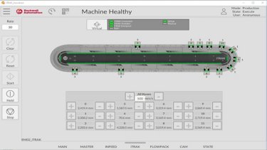
FT Optix Independent Car Transport Solution
iTRAK®, Logix, and FT Optix based solution for controlling, synchronizing, and visualizing independent vehicle transport systems.
Tags:
Hardware
Languages:
English,
Spanish,
Portuguese
Deploy Time: 45 Minutes
English
Spanish
Portuguese
Food & Beverage
Implementer
Hardware
Smart Manufacturing
FT View ME Independent Car Transport Solution
iTRAK®, Logix, and FT View ME based solution for controlling, synchronizing, and visualizing independent vehicle transport systems.
What does this application do?
This application demonstrates an integrated solution for the movement of independent carts using iTRAK, Logix control, and visualization with FactoryTalk View ME. It enables the simulation and validation of high-performance architectures, delivering flexibility, synchronization, and precision in transport. It serves as a practical reference for customers to understand gains in productivity, scalability, and the reduction of traditional mechanical components. It also accelerates the development of real projects by providing an environment ready for testing, learning, and replication.
General Characteristics
An application that demonstrates the control and synchronization of independent carts with iTRAK, using Logix and FactoryTalk View ME for operation and diagnostics. It allows validation of flexible and scalable architectures, highlighting productivity improvements and reduced mechanical complexity in industrial transport systems.
Advantages
- High operational flexibility, allowing rapid changes in layout and cart routes without mechanical modifications.
- Increased productivity and throughput due to precise and synchronized motion control.
- Reduced maintenance costs with less reliance on traditional mechanical components.
- Scalability and simplified integration with the Rockwell ecosystem (Logix and Ethernet/IP).
Limitations and Disadvantages
- Software must be updated to the latest versions.
- LOGIX control platform with MOTION capability is required.
Downloads
Please note: You will need to agree to the Terms & Conditions for each download.
Need Help?
If you need help with an application or have feedback from the Innovation Center, please contact us.
Is this application relevant to me?
This application is useful for demonstrating, in a practical and reusable way, the value of iTRAK with Logix and FactoryTalk View ME in real-world scenarios, supporting both technical and commercial discussions with customers. Additionally, it accelerates prototyping and solution standardization, reducing engineering effort and strengthening initiatives.
How can I make it work?
Requirements: products, tools, prior knowledge.
Hardware
- Notebook
- Logix Controller (CompactLogix / ControlLogix)
- iTRAK system (physical modules)
Software
- Studio 5000
- FactoryTalk View ME
Implementation Guide
You need to open the Studio 5000 software and upload the file “Itrak_V10.acd” located in the folder.
ft-view-me-independent-car-transport-solution 2.png
ft-view-me-independent-car-transport-solution 3.png
You need to open the FT Optix software and upload the file “Itrak_Innovation” through the “Open” section, as shown below:
ft-view-me-independent-car-transport-solution 4.png
ft-view-me-independent-car-transport-solution 5.png
ft-view-me-independent-car-transport-solution 6.png
You need to connect the applications according to the Studio 5000 and FT Optix manuals until you obtain the application:
ft-view-me-independent-car-transport-solution 7.jpg
ft-view-me-independent-car-transport-solution 2.jpg
ft-view-me-independent-car-transport-solution 3.jpg
ft-view-me-independent-car-transport-solution 4.jpg
ft-view-me-independent-car-transport-solution 5.jpg
ft-view-me-independent-car-transport-solution 6.jpg
ft-view-me-independent-car-transport-solution 7.jpg
FT Optix Independent Car Transport Solution
Version 2.0 - September 2026
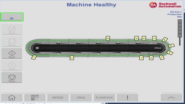
FT View ME Independent Car Transport Solution
iTRAK®, Logix, and FT View ME based solution for controlling, synchronizing, and visualizing independent vehicle transport systems.
Tags:
Hardware
Languages:
English,
Spanish,
Portuguese
Deploy Time: 45 Minutes
English
Spanish
Portuguese
Aerospace
Airports & Airlines
Automotive & Tire
Cement
Chemical
Entertainment
Fiber & Textiles
Food & Beverage
Household & Personal Care
Hydrogen
Infrastructure
Life Sciences
Marine
Metals
Mining
Mining, Metals & Cement
Oil & Gas
Power Generation
Print & Publishing
Pulp & Paper
Semiconductor
Water Wastewater
Warehouse & Fulfillment
Mass Transit
Renewable Energy
Manufacturing
Waste Management
Implementer
Software
Process Solutions
Sizing a PlantPAx system for applications with up to 5 Operator Workstations
Guide to size a PlantPAx system with up to 5 operator workstations using IAB and PSE, ensuring the correct architecture, validated components, and estimates aligned with process requirements.
What does this application do?
Sizing a PlantPAx system using the Integrated Architecture Builder (IAB) and the Process System Estimator (PSE) is essential to ensure technical accuracy and economic efficiency. IAB enables the selection and validation of the correct components for the control architecture, ensuring compatibility and proper performance, while PSE provides detailed estimates of costs and resources, aligning the project with process requirements and budget constraints. This integrated approach reduces the risks of oversizing or system failures, optimizes scalability, and ensures compliance with Rockwell Automation best practices, resulting in a robust, safe, and economically viable system.
General Characteristics
The proposed system consists of a CompactLogix controller dedicated to process applications, integrated with a set of I/O modules and intelligent drives, all connected through an industrial EtherNet/IP network. This architecture ensures precise and scalable control, reliable communication between devices, support for advanced automation strategies, and integration with supervisory systems, providing high availability, expansion flexibility, and compliance with process automation best practices.
Advantages
- Sizing using an up-to-date tool
- Use of up-to-date solutions focused on each discipline
- Evaluation of potential challenges that may arise
- Ability to develop comprehensive studies related to the sized system
Limitations and Disadvantages
The IAB (Integrated Architecture Builder) software must be updated to its latest version.
Downloads
Please note: You will need to agree to the Terms & Conditions for each download.
Need Help?
If you need help with an application or have feedback from the Innovation Center, please contact us.
Is this application relevant to me?
This type of solution is advantageous for the user because it offers simplicity, reliability, and integration in a single package. With a CompactLogix controller, I/O, and network-connected drives, the user achieves centralized control and standardized communication, reducing installation and maintenance complexity. Additionally, the architecture is scalable and flexible, allowing future expansions without significant investments, and ensures high availability and performance—resulting in greater operational efficiency, reduced downtime, and easier integration with supervisory and management systems.
How can I make it work?
Requirements: products, tools, prior knowledge.
Hardware
- Standard computer or notebook.
Software
- IAB (Integrated Architecture Builder), available for free download from the Rockwell Automation website.
Implementation Guide
Open the IAB (Integrated Architecture Builder) and, if necessary, update the program’s database. If you have internet access, you can update your IAB by clicking “Yes”.
sizing-a-plantpax-system-for-applications-with-up-to-5-operator-workstations 2.png
To start our project, click on “Existing Project” and import the provided file “App Innovation Center”.
sizing-a-plantpax-system-for-applications-with-up-to-5-operator-workstations 3.png
Select the application generated in Process System Estimator named “PlantPAx 5 OWS (PASS C)”.
sizing-a-plantpax-system-for-applications-with-up-to-5-operator-workstations 4.png
Once the application is open, you can configure the remotes, drives, IED protection relays, and local operator stations for each area of your system:
sizing-a-plantpax-system-for-applications-with-up-to-5-operator-workstations 5.png
Configurations related to I/O.
sizing-a-plantpax-system-for-applications-with-up-to-5-operator-workstations 6.png
Configurations related to drives.
sizing-a-plantpax-system-for-applications-with-up-to-5-operator-workstations 7.png
Configurations related to IED relays.
sizing-a-plantpax-system-for-applications-with-up-to-5-operator-workstations 8.png
Configurations related to local operation.
sizing-a-plantpax-system-for-applications-with-up-to-5-operator-workstations 9.png
Once the above items are configured, it is possible to evaluate the Controller Status, providing a broader view of the project as a whole. After the evaluation, simply finalize and export the bill of materials.
Note: It is important to emphasize that PlantPAx is a characterized Distributed Control System; therefore, it is essential to adopt all best practices, from system sizing to commissioning, always using the official Rockwell Automation manuals available through the provided link PlantPAx Distributed Control System | Rockwell Automation | US.
Sizing a PlantPAx System for Applications with Up to 5 Operator Workstations
Version 2.0 - September 2026
Sizing a PlantPAx system for applications with up to 5 Operator Workstations
Guide to size a PlantPAx system with up to 5 operator workstations using IAB and PSE, ensuring the correct architecture, validated components, and estimates aligned with process requirements.
Tags:
Software
Languages:
English,
Spanish,
Portuguese
Deploy Time: 30 Minutes
English
Spanish
Portuguese
Food & Beverage
Implementer
Software
Industrial Maintenance & Support
Implement AUDIT TRAIL 21CFR in FACTORYTALK OPTIX
Step-by-step guide to implement Audit Trail 21 CFR in FactoryTalk Optix, including electronic signatures and change traceability.
What does this application do?
21 CFR Part 11 is a regulation issued by the U.S. Food and Drug Administration (FDA) in 1997. It establishes the criteria under which electronic signatures and records are accepted as legal equivalents to handwritten signatures and paper records in the life sciences industry (pharmaceutical, biotechnology, medical device, etc.).
Its objective is to ensure that computer systems used in manufacturing, quality control, and regulatory documentation meet standards of:
- Authenticity
- Integrity
- Confidentiality
- Non-repudiation (a signature cannot be rejected as non-genuine)
Implementing 21 CFR is useful because it:
- Replaces paper: Reduces storage, printing, and physical handling costs.
- Streamlines processes: Enables legally valid digital workflows.
- Efficient auditing: Facilitates tracking of actions and changes in electronic records.
- Regulatory compliance: This is mandatory for companies operating under the FDA.
General Features
- Closed vs. open systems: Define controls based on who manages access.
- Electronic records: Text, graphics, audio, data, etc., in digital format.
- Electronic signatures: Legal equivalents of handwritten signatures.
- Automated audits: Records of who modified what, when, and what.
- Access controls: User authentication and role-based permissions.
Advantages
- Complete traceability: Every action is logged with a username and timestamp.
- Security: Access controls, encryption, and password policies.
- Efficiency: Digital approval workflows with electronic signatures.
- Flexibility: Configurable according to each company's specific needs.
Limitations/Disadvantages
- Implementation complexity: Requires detailed security configuration and auditing.
- Initial costs: Investment in compatible software and training.
- Maintenance: Updates, backups, and user management.
- Rigidity: Changes must follow validated procedures.
Download
Please note: You will need to agree to the Terms & Conditions for each download.
Need Help?
If you need help with an application or have feedback from the Innovation Center, please contact us.
Is this application relevant to me?
This code is defined for applications where you need to implement 21CFR.
Application areas: Food, Manufacturing, Beverage
How can I make it work?
Requirements: products, tools, prior knowledge.
Hardware
- Personal computer
Software
- FactoryTalk Optix
Prior Knowledge
- Knowledge of programming and configuration in FT Optix and application of the 21CFR standard.
Implementation Guide
Create the screen, buttons, and controls to which the electronic signature will be applied.
Image 1.1. Creating objects
Image 1.2. Creating objects (runtime)
Create the necessary users for the application from the Security tab and assign a password in the Properties section.
Image 2. Creating users
From the object library, add the Signing Workflows object by dragging it from the library to the UI.
Image 3. Signing Workflows object
Configure the AuditDialogBox object properties and assign users.
Image 4. Configure AuditDialogBox properties
Assign the Audit Signature property and the users who can change the object's condition to the variables of the objects that need to be audited.
Image 5. Configuring the Audit property in variables.
Create an Audit database, for example, embedded, from the DataStores option. Then, in the Database field of the Signing Workflows object, assign the name of the previously created database in the SigningEventLogger property.
Image 6. Definition and assignment of the Audit database.
Generate a new screen called Audit and assign the Datagrid object found in the User Interface → Data Controls → Data Grid. Once adjusted to the screen resolution, grab the SigningEventLogger property of the Signing Workflows object by dragging it to the Data Grid. From the Datagrid properties, change the setting to Descendant.
Image 7. Configure the Audit datalog.
The log of changes to the defined variables and objects is displayed in the Audit tab.
Image 8. Audit log of variables.
Image 1.1. Creating objects
Image 1.2. Creating objects (runtime)
Image 2. Creating users
Image 3. Signing Workflows object
Image 4. Configure AuditDialogBox properties
Image 5. Configuring the Audit property in variables.
Image 6. Definition and assignment of the Audit database.
Image 7. Configure the Audit datalog.
Image 8. Audit log of variables.
Implement AUDIT TRAIL 21CFR in FT Optix
Version 2.0 - September 2026

Implement AUDIT TRAIL 21CFR in FACTORYTALK OPTIX
Step-by-step guide to implement Audit Trail 21 CFR in FactoryTalk Optix, including electronic signatures and change traceability.
Tags:
Software
Languages:
English,
Spanish,
Portuguese
Deploy Time: 60 Minutes
English
Spanish
Portuguese
Aerospace
Airports & Airlines
Automotive & Tire
Cement
Chemical
Entertainment
Fiber & Textiles
Food & Beverage
Household & Personal Care
Hydrogen
Infrastructure
Life Sciences
Marine
Metals
Mining
Mining, Metals & Cement
Oil & Gas
Power Generation
Print & Publishing
Pulp & Paper
Semiconductor
Water Wastewater
Warehouse & Fulfillment
Mass Transit
Renewable Energy
Manufacturing
Waste Management
Implementer
Software
Industrial Maintenance & Support
Connect Processes with Azure IoT Operations
IoTConnect securely and scalably connects industrial plant data to Azure IoT Operations and FactoryTalk Optix using OPC UA and MQTT.
What does this application do?
The application enables industrial plant data to be securely, standardizedly, and scalably transferred to the cloud, making it possible to leverage analytics, artificial intelligence, and enterprise applications without relying on proprietary integrations. Azure IoT Operations acts as an edge data platform that connects industrial assets through OPC UA and MQTT, while FactoryTalk Optix provides visualization, monitoring, and access to operational data.
- Open and Standards-Based Architecture - Uses industry-standard protocols such as OPC UA and MQTT, reducing dependency on proprietary integrations. Facilitates interoperability between equipment from multiple vendors and existing automation systems.
- Secure OT-to-Cloud Connectivity - Provides a secure framework for transferring operational data from industrial assets to Azure. Supports modern cybersecurity strategies by implementing standardized communication and centralized data governance.
- Scalability and Flexibility - Architecture can scale from a single production line to multiple plants across the enterprise.Edge and cloud components can be expanded as operational requirements grow.
- Accelerated Digital Transformation - Creates a foundation for advanced use cases including: Predictive maintenance, Energy optimization, AI-driven recommendations, Operational anomaly detection and Digital twins.
- OT and IT Convergence - Aligns with the ISA-95 framework, enabling structured integration between industrial operations and enterprise systems. Improves visibility across production, maintenance, quality, and business functions.
- Real-Time Operational Intelligence - FactoryTalk Optix enables real-time visualization and monitoring. Azure services provide advanced analytics and AI capabilities using operational data collected from the plant floor.
- Reduced Integration Complexity - Eliminates the need for multiple custom point-to-point integrations. Provides a more maintainable and future-ready data architecture.
- Azure-Centric Ecosystem - The architecture delivers maximum value when organizations adopt Microsoft Azure services. Companies with significant investments in other cloud providers may require additional integration efforts.
- Dependence on Network Infrastructure - Reliable connectivity between OT, Edge, and Cloud environments is required. Network latency, bandwidth limitations, or connectivity interruptions may affect cloud-based use cases.
- Data Readiness Requirements - Successful analytics and AI initiatives require high-quality, contextualized operational data. Organizations with inconsistent tag structures, poor data governance, or outdated instrumentation may need preparatory work.
- Skills and Organizational Readiness - Requires expertise across OT, networking, cybersecurity, cloud technologies, and data analytics. Change management and workforce enablement may be necessary to maximize benefits.
- Initial Deployment Complexity - Integration across automation systems, historians, enterprise applications, and cloud services may require detailed architecture planning and phased implementation.
- Additional Cloud Operational Costs - Ongoing expenses may include cloud storage, data processing, AI services, and network bandwidth. Costs increase as data volume and analytics workloads grow.
- Higher Cybersecurity Responsibility - While the platform enables secure architectures, organizations must actively manage identities, certificates, access control, monitoring, and compliance requirements.
- Potential Return-on-Investment Timeline - Benefits from AI, predictive analytics, and optimization initiatives may take time to materialize, particularly when large-scale data preparation is required.
- Increased Architectural Complexity - Compared with traditional on-premise architectures, the introduction of Edge, Cloud, AI, and enterprise integration layers creates more components to manage.
- Dependence on Digital Maturity - Organizations with limited OT/IT integration maturity may not immediately realize the full value of the platform until processes, governance, and data management practices are improved.
Downloads
Please note: You will need to agree to the Terms & Conditions for each download.
Need Help?
If you need help with an application or have feedback from the Innovation Center, please contact us.
Is this application relevant to me?
This version provides a foundation for accelerating the development of a software solution that will centralize production data, capture process information, and enable its consumption by enterprise applications in Azure. The captured data can be used for:
- Energy optimization
- Failure prediction
- Operational anomaly detection
- AI-driven operational recommendations
The adaptive cloud architecture from Rockwell Automation and Microsoft connects industrial equipment and OT systems with edge technologies such as Azure IoT Operations and FactoryTalk Optix, enabling operational data to be securely collected, contextualized, and transferred to the cloud. This facilitates advanced analytics, real-time intelligence, and AI-powered applications, creating a more secure, scalable, and integrated operation. The objective is to evolve from traditional siloed architectures toward a unified ecosystem where OT, IT, Edge, Cloud, and AI converge to drive digital transformation and operational excellence.
connect-processes-with-azure-iot-operations_Adaptive Cloud Approach Architecture_1
connect-processes-with-azure-iot-operations_Adaptive Cloud Approach Architecture_1
The architecture integrates industrial automation systems with IT platforms using the ISA-95 model as a reference framework. Through FactoryTalk Optix, Azure IoT Operations, and cloud services, data flows from field devices and PLCs to enterprise applications and AI tools.
This approach enables a more connected, scalable, and intelligent operation, supporting use cases such as real-time monitoring, advanced analytics, digital twins, and enterprise-wide process optimization. By bridging OT and IT environments, organizations can unlock greater operational visibility, faster decision-making, and enhanced business outcomes.
connect-processes-with-azure-iot-operations_Factorytalk Optix + Microsoft Adaptive Cloud Approach Architecture_2
connect-processes-with-azure-iot-operations_Factorytalk Optix + Microsoft Adaptive Cloud Approach Architecture_2
How can I make it work?
Requirements: products, tools, prior knowledge.
Hardware
- ASEM 6300B-JB1 Compact Box PC 6300B-JB1AAB-CCCAN-BNNN
- Allen-Bradley ControlLogix L8 Controller
Software
- FactoryTalk Optix Studio Version 1.7.4
- FactoryTalk Optix Runtime Version 1.7.4
- Azure IoT Operations Version 1.4
Prior Knowledge
Basic knowledge of installation, configuration and integration in:
- FactoryTalk Optix
- Azure IoT Operations
- OPC UA
- MQTT
- Industrial Networking
- Kubernetes
Implementation Guide
Download the IoTConnect.zip folder and extract its contents.
- Install FactoryTalk Optix Studio and FactoryTalk Optix Runtime from FactoryTalk Hub.
- Install a Kubernetes cluster and Azure IoT Operations by following the instructions provided in the deployment guide. Deployment overview - Azure IoT Operations Preview | Microsoft Learn.
Note: This quick start guide was developed and tested on an Ubuntu machine; however, it should also work with a Windows machine.
FactoryTalk Optix
The sample FactoryTalk Optix Application in this repository contains the key components required to publish data from a control system to Azure IoT Operations. The sample application contains:
- A sample PLC program for Allen-Bradley L8 ControlLogix
- Ethernet/IP Communication Driver
- Application certificate
- OPC UA Server
- Graphical User Interface
- Read data from PLC
- Manual tag write (for when no PLC is connected)
Note: The application certificate used by the application will need to be regenerated to match your computer name.
Alternatively, follow the steps outlined below to manually create a FactoryTalk Optix application that contains OPC UA data and make it available as an OPC UA Server for use with Azure IoT Operations.
- Use FactoryTalk Optix Studio to create a FactoryTalk Optix application.
- Add Communication Driver(s) to read control system data.
- Use the RAEtherNet/IP Driver to connect to a Rockwell Automation controller.
- OPC UA is supported through the OPC UA object.
connect-processes-with-azure-iot-operations_FTOptix_CommsDrivers_3
- (Optional) Visualise the control system data on a graphical screen.
connect-processes-with-azure-iot-operations_FTOptix_runtime_app_4
- Use the Settings → Create certificate menu to create an application certificate for the FactoryTalk Optix server. This certificate will be used to authenticate the Optix OPC UA Server with Azure IoT Operations.
connect-processes-with-azure-iot-operations_FToptix_create_certificate_5
In the project folder pane, add an OPC UA Server.
- Set the Server certificate file and Server private key file properties to use the FactortyTalk Optix certificate.
- Use the Nodes to publish property to create a Configuration to publish a subset of nodes or leave blank to publish all nodes.
- Set the Endpoint URL property to use computer name or IP address so that it is accessible from the AIO box.
- Set the Use node path in NodeIds property to True to use fully qualified tag names when configuring tags in AIO. Setting this to true will ensure the OPC UA tag names use the user-friendly format of ns=<namespace>;s=Path.To.Node instead of having to specify the node id guid.
connect-processes-with-azure-iot-operations_optix_opcua_server_6
- Import the AIO certificates into the project trusted store using the instructions in the FactoryTalk Optix Studio Help.
Azure IoT Operations
- Import the FactoryTalk Optix certificate into the trusted store using instructions in Configure OPC UA certificates - Azure IoT Operations Preview | Microsoft Learn.
connect-processes-with-azure-iot-operations_empty_device_screen_7
- Open the Operations Experience site to configure a device including the endpoint profile and an asset with the right selection of data points.
connect-processes-with-azure-iot-operations_device_endpoint_config_screen_8
- In the Devices page create a device to point to the FactoryTalk Optix OPC UA Server.
connect-processes-with-azure-iot-operations_optix_device_screen_9
connect-processes-with-azure-iot-operations_empty_asset_screen_10
connect-processes-with-azure-iot-operations_asset_details_config_screen_11
connect-processes-with-azure-iot-operations_asset_data_point_config_screen_12
connect-processes-with-azure-iot-operations_optix_asset_screen_13
In the Assets page create an asset that uses the endpoint profile and then configure an data point for it.
connect-processes-with-azure-iot-operations_empty_asset_screen_10
connect-processes-with-azure-iot-operations_asset_details_config_screen_11
connect-processes-with-azure-iot-operations_empty_asset_screen_12
connect-processes-with-azure-iot-operations_empty_asset_screen_13
Tip: The node address for OPC UA tags can be seen in FactoryTalk Optix Studio.
Alternatively, you can use an OPC UA client such as UAExpert to browse the FactoryTalk Optix OPC UA Server to get the address configuration for the tags.
A tag's node id should use the format: nsu=<Optix_Application_Name>;s=Path.To.Node e.g. where the Optix application is named aio_optix1 and a tag named Variable1 has been created in folder named AIOTags, which is a child of the Model folder: nsu=AIO_optix2;s=AIO_optix2.Model.AIOTags.Variable2
connect-processes-with-azure-iot-operations_FTOptix_CommsDrivers_3
connect-processes-with-azure-iot-operations_FTOptix_runtime_app_4
adapting-conveyor-machines-with-muting-applications_Picture6.png
connect-processes-with-azure-iot-operations_optix_opcua_server_6
connect-processes-with-azure-iot-operations_empty_device_screen_7
connect-processes-with-azure-iot-operations_device_endpoint_config_screen_8
connect-processes-with-azure-iot-operations_optix_device_screen_9
connect-processes-with-azure-iot-operations_empty_asset_screen_10
connect-processes-with-azure-iot-operations_asset_details_config_screen_11
connect-processes-with-azure-iot-operations_asset_data_point_config_screen_12
connect-processes-with-azure-iot-operations_optix_asset_screen_13
Connect Processes with Azure IoT Operations
Version 1.0 - August 2026
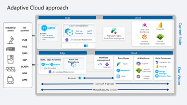
Connect Processes with Azure IoT Operations
IoTConnect securely and scalably connects industrial plant data to Azure IoT Operations and FactoryTalk Optix using OPC UA and MQTT.
Tags:
Software
Languages:
English,
Spanish,
Portuguese
Deploy Time: 120 Minutes
English
Spanish
Portuguese
Aerospace
Airports & Airlines
Automotive & Tire
Cement
Chemical
Entertainment
Fiber & Textiles
Food & Beverage
Household & Personal Care
Hydrogen
Infrastructure
Life Sciences
Marine
Metals
Mining
Mining, Metals & Cement
Oil & Gas
Power Generation
Print & Publishing
Pulp & Paper
Semiconductor
Water Wastewater
Warehouse & Fulfillment
Mass Transit
Renewable Energy
Manufacturing
Waste Management
Implementer
Software
Software Evolution
Microsoft Teams Notifications with FactoryTalk Optix
Send notifications to Microsoft Teams to share system status using messages and variables.
What does this application do?
The application was developed using FactoryTalk Optix software. Its primary objective is to send system status notifications to MS Teams, thereby streamlining information flow and facilitating decision-making based on the data transmitted. This solution leverages the advanced capabilities of FactoryTalk Optix—ranging from visualization and data management to C#-based programming structures—to keep operations at the forefront of technology. It helps address the challenges of today's industrial landscape by utilizing JSON to structure the messages being sent.
FactoryTalk Optix helps improve your processes, efficiency, and end products—all through a single, accessible tool—by leveraging collaboration, scalability, and interoperability to realize your digital transformation vision.
FT Optix stands out for its ability to connect to a wide range of industrial devices and protocols—such as OPC UA, EtherNet/IP, PROFINET, Modbus, HTTPS, and MQTT—enabling real-time integration and monitoring of equipment from various manufacturers via a unified IoT platform. Additionally, FactoryTalk Optix allows for the creation of data logs and the storage of that information in an SQL database. This facilitates the visualization of historical alarm trends and the generation of PDF reports as needed, as well as the use of REST APIs with NetLogic to make requests to external services.
Sending messages or notifications to MS Teams is a common requirement for users who need to communicate events or status updates from the plant floor to support decision-making and streamline information flow.
In this scenario, we use JSON for the message structure and Power Automate to generate the trigger that sends the message to MS Teams; internet connectivity is required.
- Use of structured code
- Flexibility in connectivity
- Impact on development time
- Notifications according to operational model
- Sending messages to MS Teams from an industrial platform
- High reliability
- Compatible with implementation in your applications
- Flexibility and scalability
- Improved information flow
- Data optimization
- Event monitoring
- Data analysis
Downloads
Please note: You will need to agree to the Terms & Conditions for each download.
Need Help?
If you need help with an application or have feedback from the Innovation Center, please contact us.
Is this application relevant to me?
Having agile notifications—with an information flow that sends alerts directly to Teams from our application—opens up a wide range of possibilities.
This application can complement your projects by enabling the delivery of notifications or information to your company's Teams chats.
It is suitable for any industry or industrial sector where there is a need to share information via Teams.
This functionality can be replicated as often as necessary across your projects, enhancing product value, optimizing implementation costs, and leveraging a continuous flow of information from the shop floor to your communication platform, such as Teams.
How can I make it work?
Requirements: products, tools, prior knowledge.
Hardware
- Controllers compatible with FT Optix connectivity
Software
- FactoryTalk Optix (V1.7.1)
Prior Knowledge
- Basic knowledge in FactoryTalk Optix and C#.
Implementation Guide
Identify the application to use: FactoryTalk Optix.
Open the file Teams_notification, in the location where you have downloaded it.
Make sure you have .NET SDK x64 installed. https://dotnet.microsoft.com/en-us/download
microsoft-teams-notifications-with-factorytalk-optix_Step1.png
Navigate the application, open the Main Window, where you can see the elements that make up this demo.
microsoft-teams-notifications-with-factorytalk-optix_Step2.png
Create an Instant Cloud Flow from your MS Power Automate platform. https://make.powerautomate.com/
microsoft-teams-notifications-with-factorytalk-optix_Step3_1.png
Select When an HTTP request is received trigger.
microsoft-teams-notifications-with-factorytalk-optix_Step3_1.png
Define the structure of the JSON to be received from FT Optix.
| { "type": "object", "properties": { "Device": { "type": "string" }, "Level": { "type": "number" }, "Temperature": { "type": "number" }, "Priority": { "type": "string" } } } |
microsoft-teams-notifications-with-factorytalk-optix_Step3_1.png
Insert a Teams action: Post a message to myself.
microsoft-teams-notifications-with-factorytalk-optix_Step3_4.png
In the content structure, use the JSON variables to display the message in Teams.
| OPTIX MESSAGE | Device: @{triggerBody()['Device']} | Level: @{triggerBody()?['Level']} | Temperature: @{triggerBody()?['Temperature']} | Priority: @{triggerBody()['Priority']} | Check your process! |
microsoft-teams-notifications-with-factorytalk-optix_Step3_5.png
After saving the flow with the configured actions, copy the HTTP URL link that we will use in FT Optix.
microsoft-teams-notifications-with-factorytalk-optix_Step3_6.png
connect-processes-with-azure-iot-operations_empty_asset_screen_10
connect-processes-with-azure-iot-operations_asset_details_config_screen_11
connect-processes-with-azure-iot-operations_asset_data_point_config_screen_12
connect-processes-with-azure-iot-operations_optix_asset_screen_13
In the project view locate the NetLogic Teams_message, which contains the code for sending messages to MS Teams chat using the JSON structure.
microsoft-teams-notifications-with-factorytalk-optix_Step4_1.png
Paste the HTTP URL link you obtained from Power Automate (Step 3.6) into line 23.
The JSON to be sent to Teams is structured within the code.
- Device: “REACTOR TANK”
- Level: varlevel
- Temperature: vartemp
- Priority: spriority
The code is compiled Teams_message.cs
microsoft-teams-notifications-with-factorytalk-optix_Step4_1.png
Run the application to see how it works.
As an example, you will see a reactor displaying water level, temperature, and priority; these variables are sent to MS Teams.
microsoft-teams-notifications-with-factorytalk-optix_Step5.png
Once the notification has been sent to Teams, we will have the information structured in our application.
microsoft-teams-notifications-with-factorytalk-optix_Step5.png
microsoft-teams-notifications-with-factorytalk-optix_Step1.png
microsoft-teams-notifications-with-factorytalk-optix_Step2.png
microsoft-teams-notifications-with-factorytalk-optix_Step3_1.png
microsoft-teams-notifications-with-factorytalk-optix_Step3_2.png
microsoft-teams-notifications-with-factorytalk-optix_Step3_3.png
microsoft-teams-notifications-with-factorytalk-optix_Step3_4.png
microsoft-teams-notifications-with-factorytalk-optix_Step3_5.png
microsoft-teams-notifications-with-factorytalk-optix_Step3_6.png
microsoft-teams-notifications-with-factorytalk-optix_Step4_1.png
microsoft-teams-notifications-with-factorytalk-optix_Step4_2.png
microsoft-teams-notifications-with-factorytalk-optix_Step5.png
microsoft-teams-notifications-with-factorytalk-optix_Step6.png
Microsoft Teams Notifications with FactoryTalk Optix
Version 1.0 - September 2026

Microsoft Teams Notifications with FactoryTalk Optix
Send notifications to Microsoft Teams to share system status using messages and variables.
Tags:
Software
Languages:
English,
Spanish,
Portuguese
Deploy Time: 30 Minutes
English
Spanish
Portuguese
Food & Beverage
Implementer
Software
Machine & Equipment Builders
Multibelt Conveyor Control
Functional description and step-by-step procedure for the MultiBelt motion control application through the Q_MAM_P_V3 AOI with position feedforward from the preceding axis.
What does this application do?
The project implements a motion control application for a MultiBelt system made up of three synchronized trains or carts on a circular path. Each train travels between a loading station and one or two unloading stations, keeping its distance from the preceding train to prevent collisions or approaches below a configured minimum distance.
The application runs on a GuardLogix/ControlLogix/CompactLogix controller and uses two main motion devices: Drive_1 and Drive_2. The train axes are named Ax_Train1, Ax_Train2 and Ax_Train3, and there is also an infeed belt axis called In_Belt along with the Ax_Converter axis, all grouped in the Axes motion group.
The logic is organized into three blocks. Main_Program governs the overall sequence: it initializes parameters and handles start-up, stop, fault reset, product simulation, MultiBelt coordination and axis management. Main_Motion_Prg executes the Q_MAM motion commands and publishes command positions for visualization or external integration. SafetyProgram manages the Safe Torque Off function of the trains through encoded safety AOIs.
The objective of this document is to commission the three-train MultiBelt application (or a configuration adapted to the need), run the cycle, observe the motion and stop it in a controlled way. The intended use mode is an environment that supports motion control, with a synchronized axis group, configured drives and a validated Safe Torque Off chain.
The problem it solves is the coordination of several independent movers on the same closed track. The logic prevents a train from catching up with the one ahead by calculating the circular distance between axes, applying a minimum distance, switching to queued mode when the gap shrinks, and propagating position feedforward from the preceding axis to the following train.
Limitations and Disadvantages
The application must not be operated on real equipment without a safety review, mechanical validation and authorization from the person responsible for the cell. Motion and safety functions must first be validated in a safe environment.
Downloads
Please note: You will need to agree to the Terms & Conditions for each download.
Need Help?
If you need help with an application or have feedback from the Innovation Center, please contact us.
Is this application relevant to me?
It is useful for anyone who needs to understand, commission or demonstrate a conveying application with several coordinated carts in Studio 5000.
Application areas: Product conveying applications with independent carts or trains on a closed track, where each mover is loaded wagon by wagon at one station and unloaded at one or two downstream stations, and where a minimum separation between movers must be guaranteed. The project also serves as a demonstration of coordinated motion control and of integration with external visualization or simulation through the tags To_E3D_T1_CmdPos, To_E3D_T2_CmdPos and To_E3D_T3_CmdPos.
How can I make it work?
Requirements: products, tools, prior knowledge.
Hardware
- 1756-L84ES controller or equivalent, major revision 36.
- Kinetix 5700/5500/5300
Software
- Studio 5000 Logix Designer version 36 or later, compatible with motion and safety projects.
- Project file Q_MAM_P_v3_GL.acd.
Prior Knowledge
- Programming in Studio 5000, CIP motion control (axis group, travel modes, position unwind and the MAM, MAJ, MAS and MRP instructions), use of Add-On Instructions, and basic understanding of safety applications with Safe Torque Off.
Implementation Guide
Application glossary: tasks, programs and routines
To interpret the procedure, it helps to first recognize the elements that make up the project. The split into three tasks matters because motion commands must run in the correct planner context, while safety runs in a separate Safety-class task.
Programs and routines
Add-On Instructions with visible logic
Q_MAM_P_V3
This is the most important motion component. It implements a Queued MAM Positive with Preceding Axis Position Feedforward: a queued positive MAM move with position feedforward based on the preceding axis. It receives the target position (in_TargetPosition), its own axis (in_Axis), the preceding axis (in_Axis_Preceding), the motion group (Cfg_MotionGroup), the motion parameters (Cfg_Q_MAM_Data) and the linked-parameter exchange structures shared between trains.
multibelt-conveyor-control_imagen 1.jpg
On start, it normalizes the target position against the track unwind (Track_Unwind): if the target exceeds the unwind, it calculates the revolution multiple and keeps the target within the circular range. It checks that the motion group is synchronized and sets error 1000 if it is not; it validates speed, acceleration, deceleration and jerk and sets error 1001 with extended codes when values are invalid; it sets error 1002 if the target tolerance is negative.
The logic calculates the circular distance between the preceding axis and its own axis using a modulo over Track_Unwind, and uses that distance to decide whether the train can move freely or must enter queued mode. In queued mode (Sts_Queued), the axis follows the preceding one while keeping Train_MinDistance: if there is room ahead it calculates a motion increment, and if not the increment is zero. It also calculates an early feedforward value (EarlyCommandValue) so that no scan is lost at the start of the move.
The PC completion condition is set when the move is within the configured tolerance and no motion is pending. The IP status indicates motion in process, and ER indicates an error in the instruction or in its internal motion commands.
AOI_MultiBelt_SingleTrain
Manages the sequence of a single train within the MultiBelt system. It determines the next target position based on the loading status, the number of loaded wagons and the unloading stations.
When first enabled, it initializes Train_Cycle_State and Mem_Cycle_State, clears errors and resets the Train_Wagon_CTU counter.
It checks that Cfg_NumberOfWagons is greater than zero, that the Cfg_Wagons array is large enough, that Cfg_TrackUnwind is valid, and that the loading and unloading positions are within the track range; if any check fails, it sets Sts_ER with codes 1005, 1006, 1007, 1008 or 1009.
State 999 corresponds to pause or error. When In_LoadingStation_ProductTrigger arrives, the AOI counts one wagon with Train_Wagon_CTU and, if not all wagons are loaded yet, calculates a new loading position by adding the size of the last loaded wagon and applying a modulo with Cfg_TrackUnwind, which generates successive targets around the circular track.
The Cmd_Q_MAM_Exe output is set when the train must move, and Out_TrainTargetPosition passes the target position to the Q_MAM_P_V3 AOI.
multibelt-conveyor-control_imagen 1.jpg
AOI_MotionPlannerCountDown
Calculates timing information for the motion planner. It reads TimeOffset, CoarseUpdatePeriod, StartTime and CycleStartTime from the motion group, reads the current CST time and converts it to planner time.
From these values it obtains TimeLeft (time remaining until the next planner call), TimeElapsed (time elapsed since the last execution) and ActualizationTimeOffset (difference between the cycle start and the group start). If the motion group is not synchronized, it sets ER.
AOI_ReadInterpolatedActualPosition
Reads interpolated positions from a CIP axis. It gets the current CST time, adds TimeOffset to it, writes that time as the axis InterpolationTime, and copies Axis.InterpolatedActualPosition and Axis.InterpolatedCommandPosition to its outputs.
In this application it is used to estimate more accurately the command position of an axis within the planner interval and to feed the feedforward calculation.
Encoded Add-On Instructions
The AOIs raM_Opr_EventCreate, _raM_Opr_DvcStateModel, _raM_Dvc_ModulePresent, raM_Dvc_CIPAxis and raM_Opr_SafeTrqOff_CD are sealed, and their internal logic cannot be inspected from the L5X. Their function is inferred from their names and visible interfaces: raM_Dvc_CIPAxis manages the CIP devices and axes associated with the drives, and raM_Opr_SafeTrqOff_CD implements the drives' Safe Torque Off.
Environment preparation
Open the Q_MAM_P_v3_GL.acd file in a programming environment that supports Logix version 36 projects, and check that the target controller is a 1756-L84ES or compatible, major revision 36.
Before continuing, confirm that the following exist: the tasks SafetyTask, _01_MainTask and _03_MotionEventTask; the programs Main_Program, Main_Motion_Prg and SafetyProgram; the axes Ax_Train1, Ax_Train2, Ax_Train3, Ax_Converter and In_Belt; the Axes motion group; and the drive modules Drive_PowerSupply, Drive_1 and Drive_2 with their addresses.
Also confirm that the required AOIs are present in the project.
Review before downloading
Check that the axes are correctly assigned to their drives and that the motion parameters are safe for the equipment or the simulator. Verify that the expected initial positions are compatible with the mechanics, that the mechanical conditions allow positive motion around the circular track, and that the system can stop the trains with the configured deceleration.
Initial command positions and stations
Train configuration and Q_MAM parameters
Download and run mode
Go online with the controller or the simulation environment and download the project. If a full download is required, put the controller in Program mode; once the download is complete, switch to Run or Remote Run mode.
Verify that _01_MainTask runs periodically every 10 ms, that _03_MotionEventTask is associated with the Motion Group Execution event, and that SafetyTask runs every 20 ms. Finally, confirm that the Axes group is synchronized through Axes.GroupSynced: this condition enables the entire subsequent sequence.
Automatic initialization
When scanning starts, Main_Rtn waits for Axes.GroupSynced to be active and starts the ProgramScanDelay timer. While ProgramScanDelay.DN is not set, Main_Rtn calls _00_InitVar and temporarily halts the rest of the application scan with TND, so that configuration and position variables are initialized before normal sequences are allowed.
_00_InitVar sets InitializeVariables and internally redefines the train command positions when they do not match the expected initial positions. It then uses GSV instructions to read the CoarseUpdatePeriod of the Axes group and convert it to seconds, and reads TravelMode, ConversionConstant and PositionUnwind from each axis to calculate Train1_Unwind, Train2_Unwind and Train3_Unwind.
If the three unwind values are equal and all three axes have TravelMode equal to 2, the common value is copied to Trains_Unwind and TrainsConfCorrect is set. The routine then loads the station positions, leaves EnableUnloadingStation1 off, configures the four wagons per train with their sizes, calculates each train's length using LBL and JMP loops, and writes the common Q_MAM parameters to Train_1_QMAM_Data, which are then copied to Train_2_QMAM_Data and Train_3_QMAM_Data.
Finally, it assigns each train's minimum distance based on the length of the preceding train and turns off RUN_CYCLE and CycleSimulationEnabled, leaving the system in a safe waiting state.
Safety check before starting
Confirm that the drives' Safe Torque Off inputs are healthy, that Train_SafeTorqueOff.Inp_SafetyInterlockOK is active, that there are no active errors in Train_SafeTorqueOff.Sts_ER, and that Train_SafeTorqueOff.Sts_TorqueDisabled correctly reflects the STO state of the trains. If a safety reset is required, momentarily set SafetyResetRequest.
SafetyProgram.MainRoutine copies that request to Train_SafeTorqueOff.Cmd_Reset and calls Trains_SafeTorqueOff, which distributes Cmd_Reset, Cfg_AutoReset, Cfg_StopCategory and Cfg_StopTime to the three internal instances _Trains_SafeTorqueOff_M1, _Trains_SafeTorqueOff_M2 and _Trains_SafeTorqueOff_M3. M1 and M2 are connected to safety signals 1 and 2 of Drive_1, and M3 to safety signal 1 of Drive_2.
Train_SafeTorqueOff.Sts_TorqueDisabled is set when all three instances report torque disabled, and Sts_MotionStop when all three report motion stopped. If any instance reports an error, its Sts_ERR and Sts_EXERR codes are copied to the global object and Train_SafeTorqueOff.Sts_ER is set. Do not request a start while safety conditions are inhibiting motion.
Application fault reset
Momentarily set FaultReset_Cmd. The FaultResetCycle sequence steps through numbered states and ends at 999 when the reset completes successfully.
Axis start-up
Verify that AxesAvailableState is active, AxesFaultedState is inactive and AxesTorqueDisabled is inactive before enabling motion. Then momentarily set StartUp_Cmd and confirm that StartUpCycle moves to state 10.
AxesOn_Cmd is set when the axes are available, not faulted, not torque-disabled and not yet activated. In _99_AxManager you should see AxT1_Ctrl_Cmd.Activate, AxT2_Ctrl_Cmd.Activate and AxT3_Ctrl_Cmd.Activate being generated, provided the corresponding axis does not have Safe Torque Disabled and the device is available. When AxT1_Ctrl_Sts.Activated, AxT2_Ctrl_Sts.Activated and AxT3_Ctrl_Sts.Activated are all active, AxesON becomes true and StartUpCycle ends at 999.
MultiBelt cycle start
With AxesON, TrainsConfCorrect and RunCycleEnabled active, momentarily set RunCycle_Cmd. RunCycleState moves to state 10 and RUN_CYCLE is latched. If running is not permitted, the sequence is invalidated with a negative state.
_01_MultiBelt sets Enable_MultiBelt_AOI when Axes.GroupSynced and InitializeVariables are true and Trains_ResetCycle is not active. This runs the three instances Train_1_AOI, Train_2_AOI and Train_3_AOI of AOI_MultiBelt_SingleTrain. Each instance receives its wagon-size array, the number of wagons, the loading and unloading positions, the track unwind, the RUN_CYCLE status, the In_ProductTrigger product trigger, the unloading-complete signal and the move-complete status of its Q_MAM, and returns Out_TrainTargetPosition.
The routine declares MultiBelt_Ready when the cycle is active and at least one train is at the loading station, and consolidates the AOI errors: if any train reports Sts_ER, MultiBelt_Cycle_Error is set and RUN_CYCLE is turned off. Each AOI sets Cmd_Q_MAM_Exe when it needs to move its train.
Q_MAM move execution
Move_Commands blocks its execution while ProgramScanDelay.DN is not set, which prevents motion commands from being sent before initialization is complete. It then calls the Q_MAM_P_V3 AOI for each train when the corresponding train AOI requests it through Cmd_Q_MAM_Exe. The chaining of preceding axes and linked parameters is circular.
Monitor Train1_QMAM.PC, Train2_QMAM.PC and Train3_QMAM.PC: each Cmd_Q_MAM_Exe must be cleared when its corresponding Q_MAM reports PC, which turns each request into a controlled execution and prevents the same command from being re-executed continuously. Also watch Train1_QMAM.ER, Train2_QMAM.ER and Train3_QMAM.ER to detect motion errors, and Sts_Queued, Sts_QueueLeader, inf_TrainsActualDistance and Sts_Mover_WayFree on each Q_MAM to validate the spacing between trains.
Product loading
For a manual test, generate a pulse on In_ProductTrigger. To use the simulation, set CycleSimulationEnabled while RUN_CYCLE is active: ProductGenerationTimeDelay times the product generation, InfeedBeltProductInput_FallingEdge generates a pulse, and that pulse sets In_ProductTrigger for one scan.
Confirm that the AOI of the train at the loading station increments its Train_Wagon_CTU counter and that the loading target advances according to the size of the loaded wagon. Repeat until the four configured wagons are complete: when the counter reaches them, the train is reset and moves on to the unloading sequence.
Product unloading
Observe Sts_TrainAtUnloadingStation1 and Sts_TrainAtUnloadingStation2 in Train_1_AOI, Train_2_AOI and Train_3_AOI. When a train reaches an unloading station, its corresponding timer (UnloadTrain1, UnloadTrain2 or UnloadTrain3) starts and, when it finishes, the unloading-complete signal Train1UnloadingCompleteSignal, Train2UnloadingCompleteSignal or Train3UnloadingCompleteSignal is generated. That signal generates Trigger_Products_Unloaded and is then cleared.
Confirm that the train AOI receives In_UnloadingComplete, advances to the next state and returns to the loading sequence. Because EnableUnloadingStation1 is initialized off, the logic may skip the first unloading station and use the second one as the main unloading point.
multibelt-conveyor-control_imagen 2.jpg
Infeed belt
When RUN_CYCLE becomes active, a start pulse is generated for _03_AxBelt and AxBelt_CycleState moves to state 10. In that state, In_Belt is jogged with the configured speed, acceleration, deceleration and jerk parameters, and once In_Belt.JogStatus confirms, the state advances to 20. When RUN_CYCLE turns off, _03_AxBelt issues another jog command at zero speed to stop the belt, and AxBelt_CycleState returns to 0 when In_Belt.JogStatus turns off.
Recommended monitoring during execution
To observe the dynamic behavior, use the trends already included in the project: Q_MAM_V3, Train1To2Distance, Train1_LinkedParametersOutput_PP, Train1_QMAM_Sts_QueueLeader, Trains, Trains1n2 and Train_1.
Normal stop
Momentarily set StopCycle_Cmd. RUN_CYCLE turns off and RunCycleState returns to 0. _01_MultiBelt clears Cmd_Q_MAM_Exe in the three train AOIs and issues stop commands for Ax_Train1, Ax_Train2 and Ax_Train3 with the configured deceleration and jerk, while _03_AxBelt stops In_Belt. Confirm that the axes have no active motion before disabling torque.
Fault or abort stop
If ApplicationMotionError occurs, StopCycle_Cmd and AbortCycle are set, RUN_CYCLE turns off, the Q_MAM commands are cleared and motion stops are executed for all three trains. Identify the source of the fault in Train1_QMAM.ER, Train2_QMAM.ER and Train3_QMAM.ER, in Sts_ER of the three train AOIs, in AxesFaultedState and in Train_SafeTorqueOff.Sts_ER.
Correct the root cause before resetting. Then run the fault reset procedure using FaultReset_Cmd, and repeat the axis start-up and cycle start only when there are no active faults.
System shutdown
First perform the normal stop with StopCycle_Cmd and confirm that there is no active motion. If the system must be left with servos disabled, deactivate the axes with AxesOff_Cmd: _99_AxManager generates the deactivation commands for the activated axes and AxesON turns off. Then apply the safety or STO conditions according to the machine procedure, and put the controller in Program mode only if the plant procedure requires it.
Expected conditions for a correct run
- Axes.GroupSynced active and TrainsConfCorrect active.
- AxesON active after start-up and RunCycleEnabled active.
- RUN_CYCLE active during operation.
- The three train AOIs without Sts_ER and the three Q_MAM instances without ER.
- The Cmd_Q_MAM_Exe commands are set on each motion request and cleared when PC is reached.
- The target positions change as wagons are loaded and the trains advance toward the unloading stations.
- The distance between trains stays above the configured minimum distance.
- The normal stop turns off the cycle and stops the trains and the belt.
multibelt-conveyor-control_imagen 1.jpg
multibelt-conveyor-control_imagen 2.jpg
Multibelt Conveyor Control
Version 1.0 - September 2026

Multibelt Conveyor Control
Functional description and step-by-step procedure for the MultiBelt motion control application through the Q_MAM_P_V3 AOI with position feedforward from the preceding axis.
Tags:
Software
Languages:
English,
Spanish,
Portuguese
Deploy Time: 30 Minutes
English
Spanish
Portuguese
Metals
Implementer
Software
Prescriptive Health Monitoring for Tank Process Variables
This solution enables the ROC to identify abnormal trends, process-dynamic changes, and progressive deviations often missed by traditional monitoring systems.
Tank operations are one of the most important operations within the production process industries. In many processes, they represent the element responsible for maintaining the continuous movement of raw materials, semi-finished products, auxiliary services, and finished products. An unplanned failure can cause significant economic losses, safety risks, environmental impacts, and production of noncompliance.
Traditionally, these are monitored through levels, but we do not access the rate of change of their process variable. However, through the PlantPAx libraries, particularly by using the P_AI objects and the Cfg_HasRoC parameter of this library, it is possible to implement a Prescriptive Health Monitoring strategy capable of detecting early signs of operational degradation before a functional failure occurs.
The solution makes it possible to identify abnormal trends, changes in process dynamics, and progressive deviations that normally go unnoticed by traditional monitoring systems.
What does this application do?
In day-to-day operation, the value of a prescriptive solution is to provide the operator and maintenance personnel with enough time to act before the failure impacts the operation, thereby preventing the pump from potentially failing and avoiding the losses associated with not taking corrective actions.
A P_AI process library associated with a level variable is used as an example, and with it we can prescribe the drop in the equipment level as the pump develops an operational malfunction:
- Prescriptive output variable Cfg_HasRoC
- Input variable, pump stop failure due to an operational situation
- Early visibility of abnormal changes in critical equipment variables, associated with and extensible to measurement variables such as flow, pressure, level, and temperature.
- Increase in operational stability, making it possible to identify gradual losses of capacity, common problems in pump suction and discharge, and possible effects extensible to cavitation and losses of hydraulic efficiency.
- Better use of PlantPAx native capabilities, without the need for new additional hardware and licensing.
- Early detection of operational equipment wear.
- Solid operational knowledge prior to larger AI implementations.
Downloads
Please note: You will need to agree to the Terms & Conditions for each download.
Need Help?
If you need help with an application or have feedback from the Innovation Center, please contact us.
Is this application relevant to me?
This application is useful for process engineers, automation and control engineers, maintenance engineers, and data scientists, so they can obtain prescriptive information from the equipment that uses it and thus generate actions that benefit the business.
How can I make it work?
Requirements: products, tools, prior knowledge.
Hardware
- 1756-L85EP
Software
Studio5000 (V37)
FactoryTalk Logix Echo Version 3.00.00
Prior Knowledge
- FT Logix Echo
- Products: Studio5000 (V37) | LogixEcho | PlantPax 5.5 | Process Libraries 5.2 | P_Ain
- Tools: Studio 5000, FT LogixEcho, PlantPax 5.5, Process Libraries
Links of Interest (internal or external)
- https://www.rockwellautomation.com/en-us/products/software/factorytalk/designsuite/studio-5000/studio-5000-logix-designer.html
- https://www.rockwellautomation.com/en-us/products/software/factorytalk/designsuite/logix-echo.html
- https://www.rockwellautomation.com/en-us/capabilities/process-solutions/process-systems/plantpax-distributed-control-system.html
- https://compatibility.rockwellautomation.com/GeneratedReleaseNote.aspx?v1=63590&v2=63590&o=&pdf=0
- https://www.rockwellautomation.com/en-us/support/documentation/technical/capabilities/plantpax-process-solutions.html
Implementation Guide
Select the file in Studio 5000
prescriptive-health-monitoring-for-tank-process-variables_Image, 1_Studio_5000_ACD.png
Open FT Logix Echo and connect it to Studio 5000. Configure FTLogixEcho so that it connects properly and operates correctly.
prescriptive-health-monitoring-for-tank-process-variables_Image, 2_FTLogixEcho_Connection.png
Configuration of Prescriptive Routines, Initial Conditions and Final Condition.
prescriptive-health-monitoring-for-tank-process-variables_Image, 3_Studio5000_Configuration.png
Configuration of Prescriptive Routines, maximum level, minimum level and derivative of volume Vs Time.
prescriptive-health-monitoring-for-tank-process-variables_Image, 4_Studio5000_Configuration_InitialCo.png
Configuration of Prescriptive Routines, Health Monitoring and level simulation Page 1/2.
prescriptive-health-monitoring-for-tank-process-variables_Image, 5_Studio5000_Configuration_Pres.png
Configuration of Prescriptive Routines, Range Change.
prescriptive-health-monitoring-for-tank-process-variables_Image, _6_Studio5000_ROC.png
ROC, real-time rate of change count.
prescriptive-health-monitoring-for-tank-process-variables_Image, 7_Studio5000_ROC.png
prescriptive-health-monitoring-for-tank-process-variables_Image, 1_Studio_5000_ACD.png
prescriptive-health-monitoring-for-tank-process-variables_Image, 2_FTLogixEcho_Connection.png
prescriptive-health-monitoring-for-tank-process-variables_Image, 3_Studio5000_Configuration.png
prescriptive-health-monitoring-for-tank-process-variables_Image, 4_Studio5000_Configuration_InitialCo.png
prescriptive-health-monitoring-for-tank-process-variables_Image, 5_Studio5000_Configuration_Pres.png
prescriptive-health-monitoring-for-tank-process-variables_Image, _6_Studio5000_ROC.png
prescriptive-health-monitoring-for-tank-process-variables_Image, 7_Studio5000_ROC.png
Prescriptive Health Monitoring for Tank Process Variables
Version 1.0 - September 2026

Prescriptive Health Monitoring for Tank Process Variables
This solution enables the ROC to identify abnormal trends, process-dynamic changes, and progressive deviations often missed by traditional monitoring systems.
Tags:
Software
Languages:
English,
Spanish,
Portuguese
Deploy Time: 60 Minutes
English
Spanish
Portuguese
Metals
Aerospace
Airports & Airlines
Automotive & Tire
Cement
Chemical
Entertainment
Fiber & Textiles
Food & Beverage
Household & Personal Care
Hydrogen
Infrastructure
Life Sciences
Marine
Mining
Mining, Metals & Cement
Oil & Gas
Power Generation
Print & Publishing
Pulp & Paper
Semiconductor
Water Wastewater
Warehouse & Fulfillment
Mass Transit
Renewable Energy
Manufacturing
Waste Management
Implementer
Software
Industrial Maintenance & Support
Connected Plant Monitor
Connected Plant Monitor centralizes real-time industrial data through MQTT, enabling asset monitoring, alarms, and events across multiple machines or sites.
What does this application do?
The Connected Plant Monitor application is a demonstration project built in FactoryTalk Optix that shows how industrial data can be collected and visualized using the MQTT communication protocol. The Connected Plant Monitor application is used to collect, consolidate, and visualize real-time and historical industrial data transmitted via MQTT from one or more field applications, providing a centralized dashboard for monitoring plant or machine information.
The main features to the Connected Plant Monitor application are:
- MQTT-based communication between industrial applications using a Publisher/Subscriber architecture.
- Collection of real-time (live) data from field devices or machine applications.
- Collection of historical data from dataloggers and event logs.
- Dashboard visualization of received operational data.
- MQTT Subscriber functionality to receive information published by the MQTT_Field application.
- Support for custom MQTT messages through configurable payload topics.
- Monitoring of connection status through indicators such as connection state and Live Data LED.
- Reception of alarm and event information in addition to process values.
- Store-and-forward capabilities for transferring historical records through MQTT topics.
- Support for multiple machines or production sites through configurable table prefixes, allowing data source identification.
- Built with FactoryTalk Optix using Runtime NetLogic components for MQTT data exchange.
The Connected Plant Monitor application provides several advantages for industrial monitoring and IIoT implementations:
- Centralized data visualization through a single dashboard that consolidates information from machines and production systems.
- Real-time monitoring by receiving live MQTT data with minimal latency.
- Scalability, as multiple machines or production sites can publish data to the same MQTT infrastructure.
- Demonstration MQTT broker. The example uses the public broker test.mosquitto.org, which is intended only for demonstration purposes and does not guarantee availability, security, or performance.
- No built-in enterprise historian. The example demonstrates MQTT data forwarding and visualization but does not provide the advanced capabilities of dedicated industrial historians such as long-term archiving, compression, redundancy, or enterprise analytics.
- Dependent on MQTT infrastructure. Communication reliability depends on broker availability, network connectivity, topic configuration, and QoS settings.
Downloads
Please note: You will need to agree to the Terms & Conditions for each download.
Need Help?
If you need help with an application or have feedback from the Innovation Center, please contact us.
Is this application relevant to me?
Primarily as a demonstration and prototyping tool rather than as a production solution.
- Integrate multiple machines or sites into a centralized dashboard using MQTT topics.
- Build proof-of-value (POV) projects showing real-time and historical data aggregation from machines or production lines.
- Demonstrate MQTT communications between industrial assets and supervisory applications.
Application areas:
- Food & Beverage, Discrete Manufacturing, OEMs (Machine Builders)
- IIoT and Digital Transformation Projects
- Multi-Machine and Multi-Site Monitoring
- Remote Equipment Monitoring
How can I make it work?
Requirements: products, tools, prior knowledge.
Hardware
- 2800E-AND-S (OptixEdge 2800,Standard (ARM),None,FT Optix L (15 tokens),Standard AB,No Conformal Coat)
Software
- FactoryTalk Optix Studio Version 1.7.5.13
- FactoryTalk Optix Runtime Version 1.7.5.1
Previous Knowledge Required
Basic knowledge of installation, configuration and integration in:
- FactoryTalk Optix
- MQTT Protocol
- Industrial Networking
- Cybersecurity Fundamentals
Implementation Guide
This application works paired with the MQTT_Asset, showing data received via MQTT protocol in form of a control dashboard.
Download the Connected_Plant_Monitor.zip folder and extract its contents.
Install FactoryTalk Optix Studio and FactoryTalk Optix Runtime from FactoryTalk Hub.
Start the MQTT_Asset
connected-plant-monitor_MQTT_Asset folder_1.png
Start the Connected Plant Monitor.
connected-plant-monitor_Connected Plant Monitor folder_2.png
Note: This quick start guide was developed and tested on an Windows machine.
Start the Field Application.
After that, open this project on another FT Optix window and run the application with FT Optix Emulator.
connected-plant-monitor_FactoryTalk Emulator_3.png
If the connection with the MQTT_Asset is working, the “Live Data” LED will be green.
connected-plant-monitor_LiveData_4.png
The data exchange is based on a Runtime Netlogic which can be found in the Netlogic folder. The Netlogic MQTTBrokerLogic is present on both applications but is configured differently.
The data exchange is based on a Runtime Netlogic which can be found in the Netlogic folder. The Netlogic MQTTBrokerLogic is present on both applications but is configured differently.
connected-plant-monitor_MQTTBrokerLogic MQTT_Asset_5.png
connected-plant-monitor_MQTTBrokerLogic Connected Plant Monitor_6.png
Here the Runtime Netlogic works as Subscriber: subscribing to the topics on which the Field Application publishes, it shows all data in the form of a dashboard.
MQTT Server
It should be activated (TRUE) only if you want to use your Uniqo application as a Broker (hence not using an existing MQTT broker, in this example test.mosquitto.org).
connected-plant-monitor_MQTT_Server_7.png
Parameters:
- IPAddress: IP address where the Broker will be instantiated
- Port: number of the port on which the broker is listening
- UseSSL: enables the use of certificates
- Certificate
- CertificatePassword
- AutoStart LEAVE TRUE
- UserAuthentication: if true only the specified users can access
- AuthorizedUsers
- IsRunning: Server status
- IsDebuggingMode NOT USED
- MaxNumberOfConnections: maximum number of clients that can connect to the Broker
- NumberOfConnections: number of active connections
MQTT Client
It must always be active (TRUE) because it is the connection with the Broker to which you publish or to which you subscribe. If you want to connect two applications, you need to set the same broker and the same port on both projects. Instead, the ClientID parameter must be different (unique) on each application.
connected-plant-monitor_MQTT Client_8.png
Parameters:
- IPAddress: broker address (test.mosquitto.org) could be external like in this case, or internal if the application work as a broker (e.g., MQTTBrokerLogic.MQTTServer.IPAddress)
- Port: broker port (1883 for test.mosquitto.org)
- UseSSL: Switch to TRUE if the broker requires certificates
- CaCertificate
- ClientCertificate
- ClientCertificatePassword
- AllowUntrustedCertificates
- UserAuthentication: Switch to TRUE if the broker requires authorized users.
- AuthorizedUsers: String array which contains Uniqo users (User1; User2; User […]);
- IsRunning NOT USED
- IsDebuggingMode NOT USED
- ClientId: this is the unique Id, different for each application that wants to participate in the data sharing/exchange
- Connected: connection status to the broker
- SentPackages STATS
- ReceivedPackages STATS
Subscriber
It must be active (TRUE) if your application needs to receive data published on the broker.
connected-plant-monitor_Subscriber_9.png
Parameters:
- LiveTags: TRUE = receive LIVE DATA
- LiveTagsFolder: this folder/Node contains a copy of the Publisher LiveTagsFolder parameter, on which the Netlogic will copy the values read from the broker.
- LiveTagsTopic: on this parameter needs to be specified the topic on which you are subscribed, and you want to receive live variables/tags values.
- LastPackageTimestamp: Timestamp of the last published packet
- StoreTables: TRUE = receive HISTORICAL DATA
- Store: DataStore on which we are saving received data. The store’s tables must be renamed with the “TablesPrefix” parameter, plus the name of the publisher application tables. Below is an example:
- Publisher application DataStore table names: Datalogger, AlarmsEventLogger
- Publisher “TablesPrefix” parameter: Station1
- Subscriber application DataStore table names: Station1_DataLogger, Station1_EventLogger Verify to have the same columns you have on the Publisher application
- StoreTablesTopic: on this parameter needs to be specified the topic on which you are subscribed, and you want to receive historical variables/tags values.
- Store: DataStore on which we are saving received data. The store’s tables must be renamed with the “TablesPrefix” parameter, plus the name of the publisher application tables. Below is an example:
- CustomPayload: Custom message without pre-defined format
- CustomPayloadMessage: Custom text message from the CustomPayloadTopic
- CustomPayloadTopic: On this parameter needs to be specified the topic on which you are subscribed, and you want to receive custom messages.
Publisher
It must be active (TRUE) if your application needs to publish data to the broker.
connected-plant-monitor_Publisher_10.png
Parameters:
- LiveTags: TRUE = publish LIVE DATA
- LiveTagsPeriod: Sending frequency (if 0000:00:00.000 send data on value change).
- LiveTagsFolder: folder (or node) that contains data to be sended
- LiveTagsTopic: /UniqoFieldHmiLiveTopic is the topic on which we are sending/publishing data
- QoS: MQTT Quality of Service (0,1,2)
- Retain: Retain message on the topic even after read
- StoreTables: TRUE = publish HISTORICAL DATA
- Store: DataStore on which we are saving our data
- TableNames: Store tables to be sended
- Table1: Datalogger
- Table2: AlarmsEventLogger
- Table (…) could be added or removed
- PreserveData NOT USED
- MaximumItemsPerPacket: define how many rows per packet to send
- MaximumPublishTime: Maximum waiting time before publishing data even if not reached the MaximumItemsPerPacket value.
- MinimumPublishTime: Minimum waiting time before publishing data when the MaximumItemsPerPacket value is reached.
- StoreTablesTopic : /UniqoFieldHmiDataLoggerTopic is the topic on which we are sending/publishing data
- QoS: MQTT Quality of Service (0,1,2)
- Retain: Retain message on the topic even after read
- TablesPrefix: A model variable containing the hypothetical name of different production sites, in this case, will be “Station1”. Into the sent packet will appear the table sent with the unique prefix corresponding to the right machine/site from which the packet arrives (Station1_AlarmsEventLogger). This is useful when we have more than one of the same machine model/more than one of the same plant configurations and we need to distinguish from which machine/plant data arrives.
- AllRows: When is TRUE, publish all the data already present in the Store Tables. Set on FALSE to publish only the data stored after the implementation of the MQTTBrokerLogic.
- CustomPayload: Custom message without pre-defined format
- CustomPayloadMessage: Custom text message published to the CustomPayloadTopic
- CustomPayloadTopic: The topic on which the message will be published
- CustomPayloadPeriod: Sending frequency of the custom message (if 0000:00:00.000 send data on value change)
- QoS: MQTT Quality of Service (0,1,2)
- Retain: Retain message on the topic even after read
connected-plant-monitor_MQTT_Asset folder_1.png
connected-plant-monitor_Connected Plant Monitor folder_2.png
connected-plant-monitor_FactoryTalk Emulator_3.png
connected-plant-monitor_LiveData_4.png
connected-plant-monitor_MQTTBrokerLogic MQTT_Asset_5.png
connected-plant-monitor_MQTTBrokerLogic Connected Plant Monitor_6.png
connected-plant-monitor_MQTT_Server_7.png
connected-plant-monitor_MQTT Client_8.png
connected-plant-monitor_Subscriber_9.png
connected-plant-monitor_Publisher_10.png
Connected Plant Monitor
Version 1.0 - October 2026
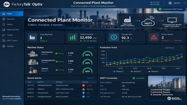
Connected Plant Monitor
Connected Plant Monitor centralizes real-time industrial data through MQTT, enabling asset monitoring, alarms, and events across multiple machines or sites.
Tags:
Software
Languages:
English,
Spanish,
Portuguese
Deploy Time: 120 Minutes
English
Spanish
Portuguese
Metals
Aerospace
Airports & Airlines
Automotive & Tire
Cement
Chemical
Entertainment
Fiber & Textiles
Food & Beverage
Household & Personal Care
Hydrogen
Infrastructure
Life Sciences
Marine
Mining
Mining, Metals & Cement
Oil & Gas
Power Generation
Print & Publishing
Pulp & Paper
Semiconductor
Water Wastewater
Warehouse & Fulfillment
Mass Transit
Renewable Energy
Manufacturing
Waste Management
Implementer
Hardware
Industrial Networks
EtherNet/IP Integration Between CompactLogix and UR5 Cobot
Integrates a CompactLogix 5480 and a UR5 cobot through EtherNet/IP to exchange cyclic data, monitor status, and validate bidirectional communication.
The implementation shown in this guide was developed using a CompactLogix 5069-L4200ERMW connected through its LAN B1 interface, a Stratix 5700 switch, a UR5 CB-Series robot with PolyScope 3, and an engineering workstation running Studio 5000 Logix Designer. The guide validates both the reading of robot information by the PLC and the transmission of data from the PLC to the UR5.
This application integrates a Universal Robots UR5 cobot with an Allen-Bradley CompactLogix 5480 controller via EtherNet/IP. The CompactLogix operates as the connection originator/scanner and the UR5 as the target/adapter, enabling cyclic exchange of process data between both controllers.
The implementation shown in this guide was developed using a CompactLogix 5069-L4200ERMW connected through its LAN B1 interface, a Stratix 5700 switch, a UR5 CB-Series robot with PolyScope 3, and an engineering workstation running Studio 5000 Logix Designer. The guide validates both the reading of robot information by the PLC and the transmission of data from the PLC to the UR5.
What does this application do?
The objective is to provide a practical, reusable reference for integrating a UR5 into a machine or automated cell controlled by Logix. The connection allows the PLC to monitor robot status, joint positions, TCP information, I/O signals, and general-purpose registers, as well as transfer commands or parameters from the CompactLogix to a PolyScope program.
Downloads
Please note: You will need to agree to the Terms & Conditions for each download.
Need Help?
If you need help with an application or have feedback from the Innovation Center, please contact us.
Is this application relevant to me?
This application is useful when the CompactLogix must coordinate the overall process sequence and the robot must operate as a subsystem within the cell. Key benefits include:
- Establishing standardized cyclic EtherNet/IP communication between CompactLogix and Universal Robots.
- Reading robot status, operating modes, safety variables, joints, TCP, I/O, and general-purpose registers from the PLC.
- Sending parameters, commands, and test values from Studio 5000 to a PolyScope program.
- Creating a reusable foundation for Ready, Busy, Done, and Fault handshakes, as well as recipe or task selection.
- Simplify diagnostics by making robot information available directly in Controller Tags.
How can I make it work?
Requirements: products, tools, prior knowledge.
Hardware
- CompactLogix 5480 (5069-L4200ERMW)
- Universal Robots UR5 CB-Series
- Allen-Bradley Stratix 5700
- Engineering Workstation (Windows, Ethernet 192.168.1.167)
Software
- Studio 5000 Logix Designer v37.x
- PolyScope 3.15.4
- UR_DataTypes.L5X
Prior Knowledge
- Basic knowledge of Studio 5000 Logix Designer and FactoryTalk Linx.
- Basic EtherNet/IP concepts.
- Basic operation of Universal Robots PolyScope 3.
Links of Interest (internal or external)
- https://www.rockwellautomation.com/en-us/products/software/factorytalk/designsuite/studio-5000/studio-5000-logix-designer.html
- https://literature.rockwellautomation.com/idc/groups/literature/documents/um/5069-um002_-en-p.pdf
- https://compatibility.rockwellautomation.com/
- https://www.universal-robots.com/articles/ur/interface-communication/ethernet-ip-guide/
- https://www.universal-robots.com/download/manuals-cb-series/user/ur5/
Implementation Guide
The following hardware and software environment is required to run the application.
Controller Revision and Software Compatibility
- The CompactLogix 5480 controller requires Studio 5000 Logix Designer v32.01 or later. Additionally, firmware v32.012 is required as the base revision for the generation. For this exercise, the physical controller was identified as running revision 37.013; therefore, it is recommended to use Studio 5000 v37.x and create the project using the same major revision as the controller to avoid incompatibilities during the download process.
IMPORTANT: If the revision installed on the controller is not available in Studio 5000, install support for that revision or consider a firmware update. A flashing process must not be interrupted by a loss of power or communication, as this could render the controller inoperable.
SAFETY: Safety states received via EtherNet/IP are useful for diagnostics and supervisory logic; however, the standard EtherNet/IP connection described here does not replace the hardwired or safety-rated safety functions required by the cell's risk assessment.
The following steps document the complete configuration used to establish and validate bidirectional communication between the CompactLogix and the UR5. The images are presented in the order of execution, and each is sequentially numbered for easy reference during the exercise.
Step 1.1
Create the Studio 5000 project and identify the controller.
Open Studio 5000 Logix Designer and create a new project. Before selecting the revision, use FactoryTalk Linx Network Browser to locate the connected CompactLogix and verify its catalog number and firmware. This application uses a 5069-L4200ERMW with IP address 192.168.1.102 and revision 37.013.
Open the Windows menu and enter “Studio 5000” in the search box. Select Studio 5000 Logix Designer to launch the programming environment in which the CompactLogix project will be created.
ethernet-ip-integration-between-compactlogix-and-ur5-cobot_01_Studio5000_Search.png
On the Studio 5000 start screen, locate the Create section and select New Project. This option opens the wizard used to define the controller family, catalog number, and revision for the application.
ethernet-ip-integration-between-compactlogix-and-ur5-cobot_02_Studio5000_NewProject.png
Step 1.2
Open FactoryTalk Linx Network Browser from Windows. This tool detects available Rockwell Automation devices on the network and allows you to verify the actual CompactLogix model before creating the project.
ethernet-ip-integration-between-compactlogix-and-ur5-cobot_04_FactoryTalkLinx_Open.png
In FactoryTalk Linx, expand the Ethernet adapter connected to the lab network. Locate the controller at address 192.168.1.102 and verify that it is a 5069-L4200ERMW before continuing.
ethernet-ip-integration-between-compactlogix-and-ur5-cobot_05_FactoryTalkLinx_Controller.png
Under Project Types, select Logix and locate the CompactLogix 5480 Controller family.
Before completing the selection, confirm the catalog number and revision of the physical device. The following steps use FactoryTalk Linx to obtain this information.
ethernet-ip-integration-between-compactlogix-and-ur5-cobot_03_Select_Controller_Family.png
Step 1.3
In Device Properties, confirm the controller catalog number and record the firmware revision shown for the device. The revision selected in Studio 5000 must be compatible with the revision installed in the CompactLogix before the project can be downloaded.
ethernet-ip-integration-between-compactlogix-and-ur5-cobot_07_Controller_Properties.png
Right-click the detected controller and select Device Properties. This window contains the information required to correctly configure the new Studio 5000 project.
ethernet-ip-integration-between-compactlogix-and-ur5-cobot_06_FactoryTalkLinx_DeviceProperties.png
Step 1.4
In the Name field, enter “Application_UR5_CompactLogix” and confirm the folder where the project file will be stored. Then select Next to continue configuring the controller.
ethernet-ip-integration-between-compactlogix-and-ur5-cobot_09_Project_Name.png
After confirming the physical device information, select CompactLogix 5480 Controller, catalog number 5069-L4200ERMW, assign the name Application_UR5_CompactLogix, and configure the project revision to match the controller. Retain the safety options required by your facility policy.
Return to Studio 5000 and, within the CompactLogix 5480 Controller family, select catalog number 5069-L4200ERMW. Make sure you select the exact model previously identified in FactoryTalk Linx.
ethernet-ip-integration-between-compactlogix-and-ur5-cobot_08_Select_5069_L4200ERMW.png
Step 1.5
Wait for Studio 5000 to finish creating and opening the project. Verify that Controller Organizer displays the 5069-L4200ERMW controller and its Ethernet interfaces before continuing with the UR5 network configuration.
ethernet-ip-integration-between-compactlogix-and-ur5-cobot_11_Studio5000_Project_Open.png
On the next screen, select a revision compatible with the revision installed in the physical controller. Retain the remaining safety parameters required for the lab, and select Finish to create the project.
ethernet-ip-integration-between-compactlogix-and-ur5-cobot_10_Project_Controller_Revision.png
Step 2.1
Verify the physical network and IP address.
The network used for this application connects all three devices to a Stratix 5700. The CompactLogix is connected through LAN B1, while the UR5 and the PC share the same Ethernet network. The Stratix operates as a Layer 2 switch; therefore, it does not need to be added to the Studio 5000 I/O tree for basic communication between the PLC and the robot.
Physically verify that the Ethernet cable used for this application is connected to the CompactLogix B1 interface. Also confirm that the NET B1 and LINK B1 indicators show network activity.
ethernet-ip-integration-between-compactlogix-and-ur5-cobot_12_CompactLogix_B1_Physical.png
Review the Stratix 5700 connections. For this application, connect the CompactLogix to port 1, the UR5 controller to port 2, and the engineering PC to port 3. Confirm that the LEDs for the ports in use indicate a link.
ethernet-ip-integration-between-compactlogix-and-ur5-cobot_13_Stratix5700_Physical.png
Step 2.2
In Studio 5000, expand I/O Configuration and review the CompactLogix B1, A1, and A2 interfaces. The UR5 integration is performed under B1, Ethernet, because this is the interface physically used in the application.
ethernet-ip-integration-between-compactlogix-and-ur5-cobot_14_Studio5000_IO_Configuration.png
NOTE: Verify that there are no duplicate IP addresses and that all three devices belong to the same subnet. The UR5 used here is a CB-Series robot with PolyScope 3; its menu layout differs from that of a UR5e with PolyScope 5.
Step 3.1
Add the UR5 as a Generic Ethernet Module.
In I/O Configuration, right-click B1, Ethernet and select New Module. Search for Generic Ethernet Module and create an ETHERNET-MODULE. The CompactLogix will be the originator of the Class 1 connection, and the UR5 will operate as the adapter.
Right-click B1, Ethernet and select New Module. This adds the EtherNet/IP representation of the UR5 controller to the I/O tree.
ethernet-ip-integration-between-compactlogix-and-ur5-cobot_15_B1_NewModule.png
In the Select Module Type window, use the search box to filter the available modules. The objective is to use a generic Ethernet module that allows the assemblies defined by Universal Robots to be entered manually.
ethernet-ip-integration-between-compactlogix-and-ur5-cobot_16_Select_Module_Type.png
Enter “Generic Ethernet Module” in the search box and select ETHERNET-MODULE. Double-click the result to open the configuration for the new device.
ethernet-ip-integration-between-compactlogix-and-ur5-cobot_17_Generic_Ethernet_Search.png
Step 3.2
When the New Module window opens, review the default values without accepting them yet. In the next step, the communication format will be changed to SINT and the IP address and assemblies for the UR5 will be entered.
ethernet-ip-integration-between-compactlogix-and-ur5-cobot_18_Generic_Ethernet_Default.png
Configure the module using the assembly parameters defined by Universal Robots:
Step 3.3
Configure the module with Name = UR5, Comm Format = Data - SINT, and IP Address = 192.168.1.150. Under Connection Parameters, enter Input Assembly 100 with Size 480, Output Assembly 112 with Size 224, and Configuration Assembly 1 with Size 0. Then select OK.
ethernet-ip-integration-between-compactlogix-and-ur5-cobot_19_UR5_EtherNetIP_Assemblies.png
In Module Properties, open the Connection tab. Set the Requested Packet Interval to 10.0 ms, keep Use Unicast Connection over EtherNet/IP enabled, and leave Inhibit Module and Major Fault On Controller If Connection Fails While in Run Mode cleared. Select OK.
ethernet-ip-integration-between-compactlogix-and-ur5-cobot_20_UR5_RPI_Unicast.png
From the PLC perspective, Input is the information received from the UR5, and Output is the information sent by the CompactLogix to the robot. An RPI of 10 ms provides a sufficiently fast update for this demonstration without using the 2 ms minimum available in the device.
Step 4.1
Download the project and align the A1/A2 Ethernet mode if required.
Open Who Active, select the CompactLogix at 192.168.1.102, and execute Download. Studio 5000 displays the standard download warning. If a second warning indicates that the project is attempting to change A1/A2 from Linear/DLR to Dual-IP, do not apply the change automatically for this application.
Open the communication path selector through Who Active. This window allows you to select the physical controller to which the newly configured project will be downloaded.
ethernet-ip-integration-between-compactlogix-and-ur5-cobot_21_WhoActive_Access.png
In Who Active, expand the Ethernet network and select the CompactLogix 5069-L4200ERMW at IP address 192.168.1.102. Verify that the displayed path points to the correct controller, and select Download.
ethernet-ip-integration-between-compactlogix-and-ur5-cobot_22_WhoActive_Controller.png
Step 4.2
Review the warning displayed before the download and confirm that the work area is safe. If the selected controller, path, and project are correct, select Download to begin the transfer.
ethernet-ip-integration-between-compactlogix-and-ur5-cobot_23_Download_Warning.png
If Studio 5000 displays a warning that the A1/A2 mode in the project differs from the controller mode, do not accept the change automatically. Select No or cancel the download to review the configuration first, because this application uses B1 for communication with the UR5.
ethernet-ip-integration-between-compactlogix-and-ur5-cobot_24_A1A2_Mode_Warning.png
Step 4.3
On the General tab of Controller Properties, locate the EtherNet/IP Mode field. If the project shows A1/A2: Dual-IP while the physical controller is set to Linear/DLR, select Change IP Mode to correct the mismatch.
ethernet-ip-integration-between-compactlogix-and-ur5-cobot_26_Controller_IP_Mode_DualIP.png
In this setup, communication with the UR5 uses B1, and ports A1/A2 are not used. Therefore, if the physical controller is already configured for Linear/DLR, cancel the download and modify the offline project so that A1/A2 are also set to Linear/DLR. This avoids unnecessarily changing the controller's existing topology.
After canceling the download, right-click the controller name in Controller Organizer and select Properties. Use this window to align the project's A1/A2 configuration with the configuration of the physical device.
ethernet-ip-integration-between-compactlogix-and-ur5-cobot_25_Controller_Properties_Menu.png
Step 4.4
In Change EtherNet/IP Mode, select A1/A2: Linear/DLR and confirm with OK. This changes the project to match the controller's current mode without altering the B1 interface used by the UR5.
ethernet-ip-integration-between-compactlogix-and-ur5-cobot_27_Change_IP_Mode_LinearDLR.png
Open Who Active again and reselect the CompactLogix at 192.168.1.102. Confirm that the communication path is correct before repeating the download.
ethernet-ip-integration-between-compactlogix-and-ur5-cobot_28_WhoActive_Redownload.png
Step 4.5
Select Download and review the standard warning again. With the A1/A2 mode now aligned, confirm the download to transfer the updated project to the controller.
ethernet-ip-integration-between-compactlogix-and-ur5-cobot_29_Download_Confirmation.png
Wait for the download process to finish and review the message pane. The procedure must end with “Complete - 0 error(s), 0 warning(s)” before continuing with the UR5 configuration.
ethernet-ip-integration-between-compactlogix-and-ur5-cobot_30_Download_Complete.png
Repeat the download and confirm that the process finishes with 0 Errors and 0 Warnings. After the download, Studio 5000 can remain in Program Mode while the robot's EtherNet/IP adapter is enabled.
Step 5.1
Enable the EtherNet/IP adapter on the UR5.
On the Teach Pendant, return to the PolyScope 3 main screen, select Program Robot, and open the Installation tab. In the side menu, select EtherNet/IP and press Enable. The indicator must turn green and display EtherNet/IP Adapter: Connected when the CompactLogix establishes the cyclic connection.
On the UR5 Teach Pendant, return to the PolyScope 3 main screen. If another program is open, use File > Exit and, from the main screen, prepare to access the robot programming environment.
ethernet-ip-integration-between-compactlogix-and-ur5-cobot_31_UR_Main_Menu.png
Select Program Robot. This option opens the environment used to edit the robot installation and enable the EtherNet/IP adapter required for the CompactLogix connection.
ethernet-ip-integration-between-compactlogix-and-ur5-cobot_32_UR_Program_Robot.png
Step 5.2
In the robot editor, select the Installation tab. The left pane displays the installation configuration options, including the available communication buses.
ethernet-ip-integration-between-compactlogix-and-ur5-cobot_33_UR_Installation_Tab.png
In the Installation side menu, select EtherNet/IP. If the heading displays “EtherNet/IP Adapter: Disabled,” press Enable to activate the UR5 communication adapter.
ethernet-ip-integration-between-compactlogix-and-ur5-cobot_34_UR_EtherNetIP_Disabled.png
Step 5.3
Wait a few seconds after enabling the adapter. When the CompactLogix establishes the connection, the heading must change to “EtherNet/IP Adapter: Connected,” and the indicator must turn green.
ethernet-ip-integration-between-compactlogix-and-ur5-cobot_35_UR_EtherNetIP_Connected.png
Save the installation under Installation > Load/Save. This retains the EtherNet/IP adapter setting the next time the installation is loaded.
With the adapter connected, open Installation > Load/Save. Press Save to store the current installation and retain EtherNet/IP enablement when this configuration is loaded again.
ethernet-ip-integration-between-compactlogix-and-ur5-cobot_36_UR_Save_Installation.png
Step 6.1
Verify I/O and import the Universal Robots UDTs.
NOTE: If the PC can ping the UR5 but Studio 5000 reports 16#0204 Connection Request Error: Connection request timed out, first verify that the EtherNet/IP Adapter is enabled and that the module IP address and assemblies match the values in this guide.
When the connection is established, Studio 5000 displays I/O OK. At this point, the generic module is exchanging 480 bytes of input data and 224 bytes of output data; however, the data appears as SINT arrays without visible meaning, for example UR5:I.Data[] and UR5:O.Data[].
Return to Studio 5000 and go online with the CompactLogix. Verify that the status at the top displays I/O OK. This confirms that the cyclic EtherNet/IP connection with the UR5 has been established correctly.
ethernet-ip-integration-between-compactlogix-and-ur5-cobot_37_Studio5000_IO_OK.png
The “raw bytes” are simply the memory block transported by EtherNet/IP between the robot and the PLC. Each byte occupies a fixed position in the message map, but a SINT array alone does not identify which positions represent Robot Mode, Safety, Joint 1, TCP X, or an integer register. The UR_DataTypes.L5X file defines UDT structures with names and data types that reflect the official map. This allows the program to work with readable members instead of manually manipulating byte offsets.
Take the project offline, go to Data Types > User-Defined > Import Data Type, and select UR_DataTypes.L5X. The import adds 14 UDTs, including the combined T2O and O2T structures and their Robot, Safety, I/O, Tool, Joints, TCP, and general-purpose register substructures.
To import the new data types, take the project offline from the Studio 5000 mode menu. The following structural changes are made to the offline project and downloaded to the PLC later.
ethernet-ip-integration-between-compactlogix-and-ur5-cobot_38_Studio5000_GoOffline.png
Step 6.2
In Controller Organizer, expand Data Types > User-Defined. Right-click User-Defined and select Import Data Type to load the official Universal Robots structures.
ethernet-ip-integration-between-compactlogix-and-ur5-cobot_39_Import_DataType_Menu.png
In the file browser, locate and select UR_DataTypes.L5X. This file contains the User-Defined Data Types that describe the format of the data exchanged with the UR5 through EtherNet/IP.
ethernet-ip-integration-between-compactlogix-and-ur5-cobot_40_UR_DataTypes_File.png
Step 6.3
In Import Configuration, verify that the 14 Data Types to be imported are displayed and that no errors are present. Retain the original names and select OK to complete the import.
ethernet-ip-integration-between-compactlogix-and-ur5-cobot_41_UR_DataTypes_Import.png
Expand Data Types > User-Defined again and verify that the Universal Robots UDTs appear, including UR_T2O_Assembly_Combined and UR_O2T_Assembly_Combined. These types allow the generic module bytes to be interpreted using readable names and structures.
ethernet-ip-integration-between-compactlogix-and-ur5-cobot_42_UR_UDTs_Imported.png
Step 7.1
Create URI/URO and map the UR5 input data with CPS.
Create two Controller Tags using the imported types: URI with UR_T2O_Assembly_Combined and URO with UR_O2T_Assembly_Combined. T2O means Target to Originator and represents UR5 → CompactLogix. O2T means Originator to Target and represents CompactLogix → UR5.
Open Controller Tags to create the two working structures that represent the flow of information between the robot and the PLC. Use New Tag or Edit Tags to add the new tags at controller scope.
ethernet-ip-integration-between-compactlogix-and-ur5-cobot_43_ControllerTags_Menu.png
Create the URI tag and assign UR_T2O_Assembly_Combined as its Data Type. Keep the tag at controller scope; URI stores the information received from the UR5.
ethernet-ip-integration-between-compactlogix-and-ur5-cobot_44_URI_Tag.png
Step 7.2
Create a second tag named URO with Data Type UR_O2T_Assembly_Combined. This structure will be used later to prepare the data that the CompactLogix sends to the robot.
ethernet-ip-integration-between-compactlogix-and-ur5-cobot_45_URO_Tag.png
In MainRoutine, add a CPS instruction to copy the input assembly to the URI UDT. The instruction must execute continuously:
Step 7.3
Open Tasks > MainTask > MainProgram > MainRoutine. Insert an available rung and prepare a copy instruction to transfer the EtherNet/IP input block to the URI structure.
ethernet-ip-integration-between-compactlogix-and-ur5-cobot_46_MainRoutine_Preparation.png
Add a CPS instruction to the rung. CPS copies the data block synchronously, preventing the logic from reading a partially updated structure during the transfer.
ethernet-ip-integration-between-compactlogix-and-ur5-cobot_47_CPS_Input_Rung.png
Step 7.4
Configure the CPS with Source = UR5:I.Data[0], Dest = URI, and Length = 1. This instruction copies the complete input assembly from the UR5 module to the URI structure on every routine scan.
ethernet-ip-integration-between-compactlogix-and-ur5-cobot_48_CPS_Input_Config.png
Length = 1 means that the destination is one complete UR_T2O_Assembly_Combined structure. CPS performs a synchronous copy to prevent the program from using a partially updated structure during the scan.
Download the project again. Set the physical CompactLogix mode switch to REM and change the controller to Remote Run from Studio 5000.
After adding the read logic, open the Studio 5000 mode menu and select Download to send the new configuration to the CompactLogix.Descargue nuevamente el proyecto. Coloque el selector
ethernet-ip-integration-between-compactlogix-and-ur5-cobot_49_Studio5000_Download.png
Step 7.5
In the confirmation window, verify that the connected controller is the 5069-L4200ERMW used for this application. If the information is correct and the area is safe, select Download.
ethernet-ip-integration-between-compactlogix-and-ur5-cobot_50_Download_Project_Confirmation.png
On the physical controller, open the mode-switch cover and set the switch to REM. This position allows Studio 5000 to change the controller between Remote Program and Remote Run without physically moving the switch again.
ethernet-ip-integration-between-compactlogix-and-ur5-cobot_51_CompactLogix_Mode_REM.png
Step 7.6
In Studio 5000, open the mode menu and select Run Mode. Because the physical switch is in REM, the option should be available to change the controller to Remote Run.
ethernet-ip-integration-between-compactlogix-and-ur5-cobot_52_Studio5000_RunMode.png
When Logix Designer requests confirmation to change to Remote Run, verify that the logic cannot cause unexpected operation, and select Yes to begin program execution.
ethernet-ip-integration-between-compactlogix-and-ur5-cobot_53_RemoteRun_Confirmation.png
Step 7.7
Open Controller Tags and select the Monitor Tags tab. This view displays the values updated by the CPS instruction in real time while the controller is running.
ethernet-ip-integration-between-compactlogix-and-ur5-cobot_54_ControllerTags_Monitor.png
Expand URI and then URI.Robot. Verify that Controller Major and Controller Minor match the UR5 PolyScope version, and observe Robot_Mode to confirm that the information is being decoded correctly.
ethernet-ip-integration-between-compactlogix-and-ur5-cobot_55_URI_Robot_Data.png
Validate and interpret the data received from the UR5.
Under Controller Tags > Monitor Tags, expand URI.Robot. During the test, Controller Major = 3 and Controller Minor = 15 were observed, consistent with PolyScope 3.15.4. The value Robot_Mode = 5 corresponds to the robot's IDLE status under this test condition. This match confirms that the CPS is correctly aligning the byte map with the UDTs.
The most useful branches for monitoring are:
Return to the main URI level and review the available branches: Robot, Safety, I/O, Tool, Joints, TCP, Bit, Int, and Float. These structures organize the data received from the robot and simplify its use in control and diagnostic logic.
ethernet-ip-integration-between-compactlogix-and-ur5-cobot_56_URI_Data_Groups
Prepare the CompactLogix-to-UR5 write path.
To transmit data to the robot, add a second CPS that copies the URO structure to the output assembly. During initial preparation, place an AFI before the CPS to keep writing disabled until the PolyScope test program is complete.
To prepare the CompactLogix → UR5 direction, return to MainRoutine and insert a second rung. Temporarily place an AFI at the beginning of the rung and add a CPS after it. The AFI keeps the output copy disabled while configuration is being completed.
ethernet-ip-integration-between-compactlogix-and-ur5-cobot_57_CPS_Output_with_AFI.png
Configure the second CPS with Source = URO, Dest = UR5:O.Data[0], and Length = 224. Keep the AFI ahead of the instruction to prevent the PLC from writing the output assembly before the UR5 test program is created.
ethernet-ip-integration-between-compactlogix-and-ur5-cobot_58_CPS_Output_Config.png
The value 224 corresponds to the 224 SINTs/bytes of the Output Assembly configured in the Generic Ethernet Module. While the AFI is present, values prepared in URO are not copied to UR5:O.Data[].
Step 10.1
Create a PolyScope test program to read an integer register.
On the Teach Pendant, create an Empty Program and verify that Program Loops Forever remains enabled. Select the <empty> node, open Structure, and insert an Assignment under Advanced.
On the Teach Pendant, open Program Robot and select Empty Program. A simple new program is created that only reads an EtherNet/IP register and contains no motion instructions.
ethernet-ip-integration-between-compactlogix-and-ur5-cobot_59_UR_Empty_Program.png
Select Robot Program in the tree and confirm that Program Loops Forever is enabled. This option repeats the register read continuously while the program is running.
ethernet-ip-integration-between-compactlogix-and-ur5-cobot_60_UR_Program_Loops_Forever.png
Select the <empty> node in the program tree and open the Structure tab. The instructions required for the communication test are inserted from here.
ethernet-ip-integration-between-compactlogix-and-ur5-cobot_61_UR_Select_Empty_Structure.png
Step 10.2
In Structure, open the Advanced tab and select Assignment. This adds an assignment line to the UR5 program for storing the value received from the PLC.
ethernet-ip-integration-between-compactlogix-and-ur5-cobot_62_UR_Assignment_Node.png
Configure the Assignment as follows:
Integer registers 0…23 belong to the range reserved by Universal Robots for Fieldbus/PLC interfaces. This test uses register 23 to avoid interfering with registers that may be used by other robot programs.
Select the new Assignment and, under Command, create or select the PLC_Value variable. Under Expression, enter read_input_integer_register(23) to read integer register 23, which is reserved for the Fieldbus/PLC interface.
ethernet-ip-integration-between-compactlogix-and-ur5-cobot_63_UR_PLC_Value_Assignment.png
Add a Wait of 0.1 s. The delay is not required for EtherNet/IP, but it simplifies the test and prevents the assignment from executing at the maximum PolyScope cycle rate.
Add a Wait instruction after the Assignment and set the time to 0.1 s. The program reads PLC_Value cyclically, with a short pause between iterations to make the test easier to observe.
ethernet-ip-integration-between-compactlogix-and-ur5-cobot_64_UR_Wait_01s.png
Step 10.3
Save the program using File > Save As with the name PLC_EIP_Test.urp, and confirm that the robot installation is also saved.
Open the File menu in the upper-left corner of the Teach Pendant and select Save As. This option saves the test program under a name that is independent of other programs already on the robot.
ethernet-ip-integration-between-compactlogix-and-ur5-cobot_65_UR_SaveAs.png
Under Save Program, enter PLC_EIP_Test as the file name and confirm with Save. Verify that the program is stored as PLC_EIP_Test.urp.
ethernet-ip-integration-between-compactlogix-and-ur5-cobot_66_UR_Save_PLC_EIP_Test.png
Open Installation > Load/Save and review the installation status. If the Save button is enabled, press it to store any pending changes. If it is disabled, the installation is already saved.
ethernet-ip-integration-between-compactlogix-and-ur5-cobot_67_UR_Save_Installation_Check.png
Replace the AFI with controlled write enable logic.
In Studio 5000, create a BOOL Controller Tag named UR_Enable_Write. Replace the AFI in the output rung with an XIC associated with this tag. This allows writing to the UR5 to be enabled or blocked without modifying the logic during testing.
In Studio 5000, open Controller Tags and create a new BOOL tag named UR_Enable_Write. This bit is used as an explicit permission to enable or block writes from the CompactLogix to the UR5.
ethernet-ip-integration-between-compactlogix-and-ur5-cobot_68_UR_Enable_Write_Tag.png
Return to MainRoutine and replace the AFI in the output rung with an XIC associated with UR_Enable_Write. Initially leave the bit at 0 so that the output CPS remains disabled until the test.
ethernet-ip-integration-between-compactlogix-and-ur5-cobot_69_UR_Enable_Write_XIC.png
IMPORTANT: Before enabling UR_Enable_Write, keep the Speed Slider and physical output masks in URO at zero if you do not want to take control of those resources. This test modifies only URO.Int.Registers[23].
Download the project, leave the controller in Remote Run, and enter the value 123 in URO.Int.Registers[23].
Download the updated project, place the controller in Remote Run, and open Controller Tags > Monitor Tags. Expand URO.Int.Registers and enter the value 123 in URO.Int.Registers[23], while keeping UR_Enable_Write at 0.
ethernet-ip-integration-between-compactlogix-and-ur5-cobot_70_URO_Int_Register23.png
Step 12.1
Run the UR5 test and validate bidirectional communication.
On the Teach Pendant, initialize the robot until it reaches START, load PLC_EIP_Test, and press Play. On the Variables tab, observe PLC_Value. Before enabling the output CPS, the value may remain at 0.
On the Teach Pendant, initialize the robot and verify that the screen shows Normal status and that the START button allows initialization to complete. Robot-arm movement is not required for this test, but the robot must be properly initialized to execute the program.
ethernet-ip-integration-between-compactlogix-and-ur5-cobot_71_UR_Initialize_Start.png
Load PLC_EIP_Test if it is not active, and press the Play button at the bottom of the Teach Pendant. The program begins repeatedly executing the Assignment and the configured Wait.
ethernet-ip-integration-between-compactlogix-and-ur5-cobot_72_UR_Play_Program.png
Step 12.2
With the program running, open the Variables tab and locate PLC_Value. Before enabling the PLC write, confirm the displayed value. In the initial test, the value is 0 because the output CPS is still blocked.
ethernet-ip-integration-between-compactlogix-and-ur5-cobot_73_UR_PLC_Value_Zero.png
Return to Studio 5000 and enable UR_Enable_Write using Toggle Bit. The XIC becomes true and the CPS begins copying URO to UR5:O.Data[0]. The value 123 sent in URO.Int.Registers[23] is received by the UR5, and the read_input_integer_register(23) instruction updates PLC_Value.
Return to Studio 5000 and, while online, right-click the UR_Enable_Write XIC and select Toggle Bit, or change the tag to 1 from Monitor Tags. When the XIC is enabled, the CPS begins copying URO to UR5:O.Data[0].
ethernet-ip-integration-between-compactlogix-and-ur5-cobot_74_Studio5000_Toggle_Write.png
Step 12.3
PLC_Value = 123 on the Teach Pendant validates the return path. Both UR5 → CompactLogix through URI and CompactLogix → UR5 through URO are now verified.
Return to the Variables tab on the Teach Pendant and observe PLC_Value. The value must change to 123, demonstrating that URO.Int.Registers[23] was sent through EtherNet/IP and read correctly by read_input_integer_register(23).
ethernet-ip-integration-between-compactlogix-and-ur5-cobot_75_UR_PLC_Value_123.png
The completed application establishes bidirectional EtherNet/IP communication between a CompactLogix 5480 and a UR5 CB-Series robot. URI receives and decodes robot information, while URO sends registers to PolyScope. The integer-register test confirms that the network configuration, assemblies, UDTs, and CPS instructions work together correctly.
This foundation supports Ready, Start, Busy, Done, and Fault handshakes, as well as recipe or task selection. For production, assign registers clearly, document the handshake, and validate behavior during communication loss, restarts, and safety-state changes.
EtherNet/IP Integration Between CompactLogix and UR5 Cobot
Version 1.0 - October 2026

EtherNet/IP Integration Between CompactLogix and UR5 Cobot
Integrates a CompactLogix 5480 and a UR5 cobot through EtherNet/IP to exchange cyclic data, monitor status, and validate bidirectional communication.
Tags:
Hardware
Languages:
English,
Spanish,
Portuguese
Deploy Time: 60 Minutes
English
Spanish
Portuguese
Metals
Aerospace
Airports & Airlines
Automotive & Tire
Cement
Chemical
Entertainment
Fiber & Textiles
Food & Beverage
Household & Personal Care
Hydrogen
Infrastructure
Life Sciences
Marine
Mining
Mining, Metals & Cement
Oil & Gas
Power Generation
Print & Publishing
Pulp & Paper
Semiconductor
Water Wastewater
Warehouse & Fulfillment
Mass Transit
Renewable Energy
Manufacturing
Waste Management
Implementer
Software
Software Evolution
SMS Notifications using Factory Talk Optix
Send SMS text messages, to share the status of a system, using short messages directly mobile
What does this application do?
The application has been developed using FactoryTalk Optix software. Its main purpose is to send notifications via SMS text messages to indicate system statuses, facilitating the flow of information and decision-making based on the information sent. This solution utilizes the advanced features that FactoryTalk Optix can deliver in terms of visualization, data management, and programming structures using C#. The platform allows us to keep our operations at the forefront with technological solutions that help us meet the challenges of today's industry, leveraging the use of SMS provider APIs. In this example, we do not use hardware such as a GSM modem.
FactoryTalk Optix can help improve your processes, efficiency, and end products—all with one easy-to-access tool. Leverage collaboration, scalability, and interoperability to achieve your digital transformation vision.
FT Optix stands out for its ability to connect to a wide variety of industrial devices and protocols such as OPC UA, Ethernet/IP, Profinet, Modbus, HTTPS, MQTT, and many others, enabling real-time integration and monitoring of equipment from different manufacturers from a single IoT platform. In addition, FactoryTalk Optix has the ability to create data logs and save this information in an SQL database. This allows you to view historical alarm trends and create PDF reports as needed. It also allows you to use REST API with NetLogic to make requests to external services.
Sending SMS text messages is a necessity that many users seek in order to notify events or statuses from the plant floor for decision-making and to have an optimized flow of information. In this case, we will use REST API with an SMS provider (in this case, we will use Twilio, although there are others), and internet connectivity is required.
- Use of structured code
- Flexibility in connectivity
- Impact on development time
- Notifications according to operational model
- Sending SMS text message from industrial platform
- High reliability
- Compatible with implementation in your applications
- Flexibility and scalability
- Improved information flow
- Data optimization
- Event monitoring
- Data analysis
Downloads
Please note: You will need to agree to the Terms & Conditions for each download.
Need Help?
If you need help with an application or have feedback from the Innovation Center, please contact us.
Is this application relevant to me?
Having agile notifications with a flow of information associated with sending SMS text messages directly from our application has a wide range of possibilities.
This application can complement your projects by sending notifications or short information in text format to the mobile phone of any user who requires it in their operation.
It applies to any industry or industrial segment where you want to send information via SMS text messages with internet connectivity using an SMS provider.
This functionality can be replicated as many times as necessary in your projects, increasing the value of your products, optimizing implementation costs, and exploiting the continuous flow of information from the plant floor to wherever you are with your mobile phone.
How can I make it work?
Requirements: products, tools, prior knowledge.
Hardware
- Controllers compatible with FT Optix connectivity
Software
- FactoryTalk Optix (V1.7.1)
Prior Knowledge
- Basic knowledge in FactoryTalk Optix and C#.
Implementation Guide
Identify the application to use: FactoryTalk Optix.
Open the file Send_SMS, in the location where you have downloaded it.
Make sure you have .NET SDK x64 installed.
https://dotnet.microsoft.com/en-us/download
sms-notifications-using-factory-talk-optix_Step 1.png
2.1 Navigate the application, open the Main Window, where you can see the elements that make up this demo.
sms-notifications-using-factory-talk-optix_Step 2 1.png
2.2 In the project view locate the NetLogic MessageSMS, where the code for send SMS text messages is located.
sms-notifications-using-factory-talk-optix_Step 2 2.png
3.1 Open the C# code to send SMS text messages
Ensure you install the Twilio SDK for C#. You can install it using the console NuGet à Manage Nuget Packages, searching for Twilio.
sms-notifications-using-factory-talk-optix_Step 3 1.png
3.2 Ensure you have a Twilio account for sending SMS messages.
Obtain credentials in Twilio Console:
- Account SID
- Auth Token
- Twilio phone number enabled for SMS
Used in the following lines of code:
- 25 const string accountSid = Account SID
- 26 const string authToken = Auth Token
- 44 from: new PhoneNumber (Número de Twilio)
sms-notifications-using-factory-talk-optix_Step 3 2.png
The function parameters are used to assign a pair of contacts (name1, phone1, name2, phone2) to send SMS text messages. Additionally, you can add custom text (textsms).
The SMS text message to be sent is structured as follows: body: $"{textsms} - {person.Value} Level: {varlevel}% Temp: {vartemp}C - send by Optix"
Result: Text – Person1 Level: 85% Temp: 180C – send by Optix
MessageSMS.cs solution code should be built/compile.
On the SMS button, secure the MouseClick event with the /MessageSMS/sms_send method and ensure that the arguments are assigned.
Run the application to see how it works.
sms-notifications-using-factory-talk-optix_Step 4.png
As an example, you can see a boiler with the water level and temperature; these variables are sent to the contacts along with a text message.
sms-notifications-using-factory-talk-optix_Step 5.png
Once the SMS text message has been sent to the mobile number, we will have the information that we structured in our application.
sms-notifications-using-factory-talk-optix_Step 6
sms-notifications-using-factory-talk-optix_Step 1.png
sms-notifications-using-factory-talk-optix_Step 2 1.png
sms-notifications-using-factory-talk-optix_Step 2 2.png
sms-notifications-using-factory-talk-optix_Step 3 1.png
sms-notifications-using-factory-talk-optix_Step 3 2.png
sms-notifications-using-factory-talk-optix_Step 4.png
sms-notifications-using-factory-talk-optix_Step 5.png
sms-notifications-using-factory-talk-optix_Step 6.PNG
SMS Notifications using Factory Talk Optix
Version 2.0 - October 2026

SMS Notifications using Factory Talk Optix
Send SMS text messages, to share the status of a system, using short messages directly mobile
Tags:
Software
Languages:
English,
Spanish,
Portuguese
Deploy Time: 30 Minutes
Items Per Page:
