
User interface
Use the
FactoryTalk Design Workbench
user interface (UI) to create projects, specify which
panes to view, and reset to the default layout if necessary. FactoryTalk Design Workbench user interface
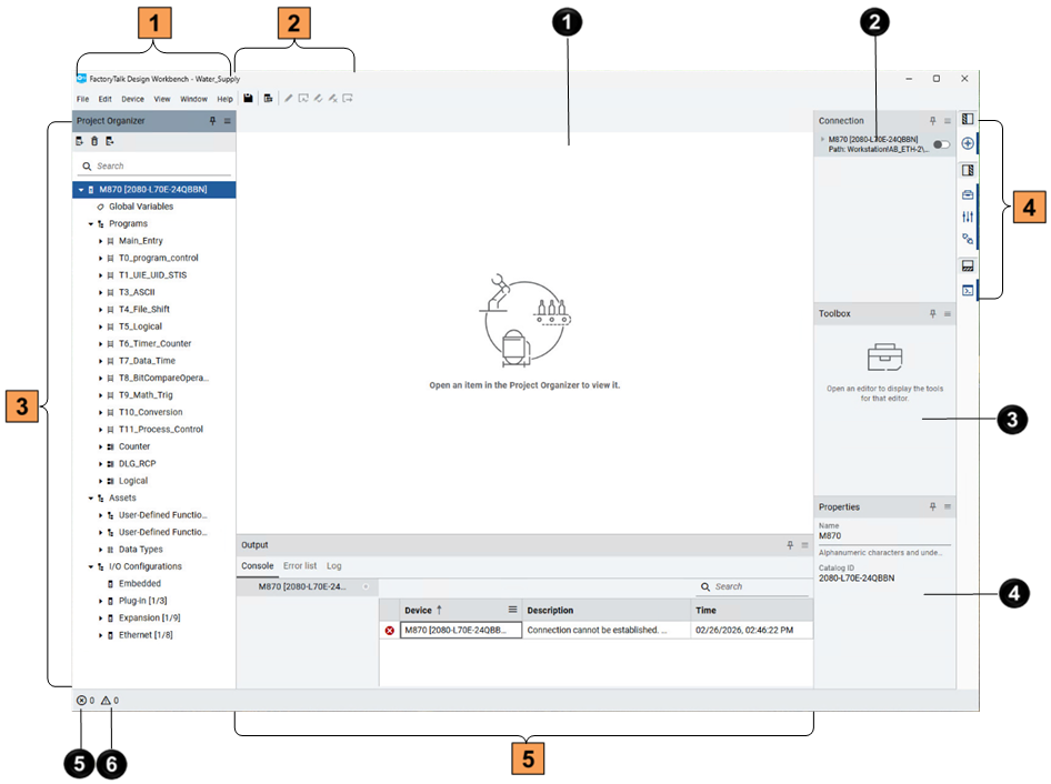
Item | Name | Description |
|---|---|---|
 | Toolbar | Contains:
|
 | Displays the devices, I/O configurations, and program elements of the project in an organized tree view. | |
 | Contains:
| |
 | Workspace | Contains the options to configure devices and build programs. The content varies
with the page you open. |
 | Connection pane | For each added device, the Connection pane contains:
|
 | Contains the logic elements and instructions that can be added to the opened
language editor. | |
 | Displays the properties of a selected item. You can edit the properties in the Properties pane. | |
 | Error indicator | Displays the total number of errors in the current project, counting only errors
from POUs that are built and verified. |
 | Warning indicator | Displays the total number of warnings in the current project, counting only errors
from POUs that are built and verified. |

 indicates that there are ongoing or unsaved RMC changes. Before
reconnecting to the controller, you can choose to resume editing.
indicates that there are ongoing or unsaved RMC changes. Before
reconnecting to the controller, you can choose to resume editing. indicates that testing is in progress on a POU. Before reconnecting
to the controller, you can choose to continue testing the POU.
indicates that testing is in progress on a POU. Before reconnecting
to the controller, you can choose to continue testing the POU.
Provide Feedback