System Configuration Tool
To access the System Configuration Tool
From the View menu, click
System Configuration Tool
.To use
Trusted®
controllers, configure the system using the System Configuration Tool
. Use the System Configuration Tool
to create the SYSTEM.INI text file used to configure the operational parameters within a Trusted
controller.From the
System Configuration Tool
, load existing SYSTEM.INI files, save new or modified files, erase the buffer, and import I/O connection files.Task | Procedure |
|---|---|
Load the buffer from a file |
|
Save the buffer to a file |
|
Erase the buffer | From the System Configuration Tool , in the File menu, click Erase Buffer . |
Import an I/O connection file |
|
TIP:
Even if a controller contains two TMR processors, the
System Configuration Tool
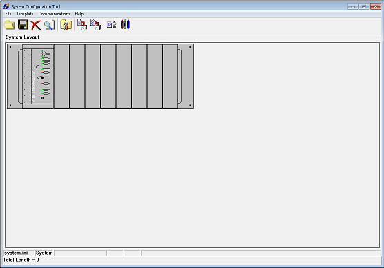
only displays one.The
System Configuration Tool
displays the system layout of the Trusted
controller chassis. The layout displayed in the System Configuration Tool
must match the physical controller.To configure the
Trusted
controller, perform the following from the System Configuration Tool
:- Create and configure system templates
- Configure theTrustedTMR Processor
- Assign modules to theTrustedSystem
- Configure I/O modules
- Configure the Communications Interface module
- Set the Communications port
- Generate the SYSTEM.INI
- Download the SYSTEM.INI
- Upload the SYSTEM.INITIP: To configure the controller, the maintenance enable key switch must be in theMaintainposition. You must connect your workstation to theTrustedTMR Processor front panel diagnostic port using the TC-304-01 Serial Maintenance Cable or via Ethernet using an 8153 Communications Interface Adapter located on the back of the T8151B Communication Interface.
Provide Feedback