Use Modbus Communications
Modbus
CommunicationsA
Trusted®
controller supports Modbus®
communications and acts as a Modbus
master or Modbus
slave. A Modbus
master can have Modbus
master slaves. The Trusted
controller uses either Ethernet or serial ports for Modbus
communications.Configure
Modbus
communications in the T8151 Communications Interface
. For more information on configuring Modbus
communications, refer to the Product Description PD-T8151B, Trusted
Communication Interface.
TIP:
Before using
Modbus
communications,
specify the Modbus
address format (Hexadecimal or Decimal) in the CAM
Trusted
settings from the Tools
> Options
menu. The
System Configuration Tool
reads Modbus
addresses for variables
in Decimal format.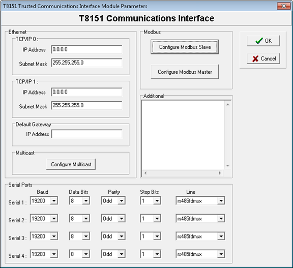
When configuring
Modbus
communications, define these properties:Property | Description |
|---|---|
TCP/IP | The Ethernet ports are listed as TCP/IP 0 and TCP/IP 1 but are described on the front panel as Ethernet 1 and 2. Each port has an IP address and a subnet mask. The subnet mask defines the network address portion of the whole IP address. Devices on one network address cannot communicate with devices on other networks without a gateway.Set the Ethernet port IP addresses for both ports on a communication interface to separate networks. For example, the IP addresses covered by the subnet mask should be different. If port 1 and 2 are on the same network, only one port can communicate. Examples
|
Default Gateway | The address of a device that allows access to other networks. Since both ports must be on different networks, only one of the ports can be on the same network as the gateway, and only this port can use the gateway. The gateway allows the port to communicate with IP addresses outside its own network, for example, across a site local area network (LAN) or even onto the Internet, perhaps to allow remote diagnostics. Example A communications interface Ethernet port is connected to network 192.200.11.x.
|
Multicast | For information on configuring Peer-to-Peer multicasting, refer to the Product Description PD-T8151B, Trusted Communication Interface. |
Serial Ports | Define the four serial ports for baud rate, data bits, parity, stop bits, and line type. The front panel serial port is port 0 and cannot be defined. The normal pattern uses two bits after each data byte. This pattern is either odd/even parity and one stop bit or no parity and two stop bits.
|
Additional | Enter configuration commands not supported by the System Configuration Tool . |
Prerequisites
- Before configuringModbuscommunications, create variables withModbusaddresses and (optional) extended attributes. ConfigureModbuscommunications in theT8151 Communications Interface.
To configure
Modbus
communications- From theVIEWmenu, clickSystem Configuration Tool.
- In thewindow, right-click an empty slot and selectTrustedSystem Configuration ToolT8151: Communications Interface.The slot displays a communications interface.
- Click the communications interface in the slot.TheT8151windowTrustedCommunications Interface Module Parametersappears.
- Define the properties for theModbuscommunications:
- TCP/IP Ethernet ports
- Default gateway
- Multicast for enhanced peer-to-peer
- Serial ports
- ConfigureModbusmaster and slave protocols for use in the communication services for controllers.
- Define additional configuration commands not supported by theSystem Configuration Tool.
Provide Feedback