Defining Modbus Master Slave Messages
Modbus
Master Slave MessagesSet up an individual list of messages (commands) for each slave device.
A
Modbus®
master supports a maximum of 400 messages from slave devices. A Modbus
master Modbus
read commands cause data to be read from the slave device to the Modbus
master, while Modbus
write commands cause data to be copied from the Modbus
master to the slave device. Define a sequence of broadcast write commands, which a Modbus
master can send to multiple Modbus
RTU slaves without requiring an acknowledgment. The AADvance controller can control and monitor individual Modbus
master objects and their slave links.Task | Procedure |
|---|---|
Add messages for a Modbus master slave |
|
Remove messages from a Modbus master slave |
|
Properties for adding messages are:
Command | Read Coils | Reads the coil status in a remote slave device. Each message has a maximum
Count of 2000 coils. |
Read Discrete Inputs | Reads the discrete input (coil) status in a remote slave device. Each message has
a maximum Count of 2000 inputs. | |
Read Holding Registers | Reads the holding registers in a remote slave device. Each message has a maximum
Count of 125 registers. | |
Read Input Registers | Reads the input registers in a remote slave device. Each message has a maximum
Count of 125 registers. | |
Write Coils | If the Master Space is Coils , forces each coil in a sequence of
coils on and off in a remote slave device.If the Master Space is Discrete Inputs , writes to each discrete
input in a remote slave device.Each message has a maximum Count of 2000 coils or inputs. | |
Write Holding Registers | Writes to the holding or input registers. Each message has a maximum Count
of 125 registers. | |
Master Space | Depending on the Command , possible values are Coils , Discrete
Inputs , Input Registers , or Holding Registers .
| |
Slave Address | Possible values are 1 to 65536; the default value is 1. | |
Master Address | Possible values are 1 to 65536; the default value is 1. | |
Count | When the Command is Read Coils , Read Discrete Inputs , or
Write Coils, the value ranges from 1 to 2000; the default value is 1.When the Command is Read Input Registers , Read Holding
Registers , or Write Holding Registers , the value ranges from 1 to
125; the default value is 1.
TIP:
Use up to 31 messages. Using more than 31
messages does not send any messages to the controller after downloading code to
the controller.
| |
Control | The address of a control register. When using a control variable, the Modbus address of the coil register. Possible values range from
1 to 65536, or 0 to disable; the default value is 0. When the address of a control
variable is unspecified, the link is automatically enabled once the controller
starts. The application may write to the control variable to switch the state of
the master slave.True = The slave is not polled False = The slave is polled for data | |
Comment | Plain text | |
All
Modbus
master objects defined for a project (Modbus
RTU or Modbus
TCP) function independent of each other. Each master polls its associated slave devices, to send the messages scheduled for the slaves.For
Modbus
RTU, a master polls its slave devices one at a time, executing one message for each slave in turn. Different slaves attached to the same master usually need a different numbers of messages. To accommodate this, the master proceeds to work through the messages listed for the slaves, one message for each pass, returning to the first message for a slave after it has sent the last one. This means that some messages (for slaves with fewer scheduled messages) are sent more than once during a polling cycle. The polling cycle completes when the Modbus
master has made an equal number of polls to each slave and has sent every message; the cycle then starts again.Example
This example displays the message schedule for a master with three slaves that require a different number of messages:
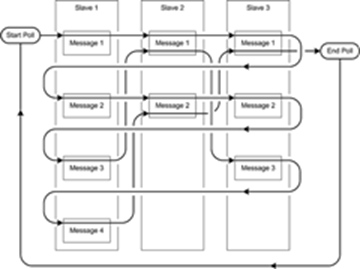
The total number of messages that the master must send in a complete polling cycle is equal to the largest number of messages scheduled for any slave, multiplied by the total number of slaves. In the previous example, the total number of messages is 4 x 3 = 12. Nine messages are specified for the three slaves. The message scheduling mechanism sends three of these messages twice, making a total of 12 messages sent. This table lists the sequence of messages for the serial communications link in the previous example:
Sequence Number | Slave | Message | Remarks |
|---|---|---|---|
1 | 1 | 1 | |
2 | 2 | 1 | |
3 | 3 | 1 | End of first pass through all the slaves |
4 | 1 | 2 | |
5 | 2 | 2 | End of pass through slave 2 |
6 | 3 | 2 | |
7 | 1 | 3 | |
8 | 2 | 1 | Repeat message |
9 | 3 | 3 | End of pass through slave 3 |
10 | 1 | 4 | End of pass through slave 1 |
11 | 2 | 2 | Repeat message |
12 | 3 | 1 | Repeat message; end of poll |
Provide Feedback