Defining a Modbus Master
Modbus
MasterThe AADvance controller can fulfill the role of a
Modbus®
master to one or more Modbus
slave devices. Slave devices can include programmable logic controllers, remote devices (typically with little or no processing capability) and, more rarely, other functional safety controllers ( Trusted®
or AADvance). A controller can have a maximum of 32 Modbus masters.The AADvance controller supports the
Modbus
TCP protocol, the Modbus
RTU protocol, and a subset of Modbus
commands. Each Modbus
master can connect to only one Modbus
TCP slave device or to one or more Modbus
RTU slave devices. Use Modbus
TCP with Ethernet ports and Modbus
RTU with point-to-point or multi-drop serial links. Serial links can use a full-duplex, 4-wire connection, or a half-duplex, 2-wire connection.
WARNING:
The
Modbus
master functionality has a safety
integrity level of zero (SIL0) and should only be used for non-safety applications.To use the AADvance controller as a
Modbus
master, perform the following:- Define the physical connections from the controller to the slave devices
- Configure the characteristics for serial ports
- Set up the project forModbusmaster and configure the application
The
Modbus
master functionality is built into the 9110 processor module and the physical communication ports are located on the 9100 processor base unit. This example shows possible arrangements for
Modbus
master connections: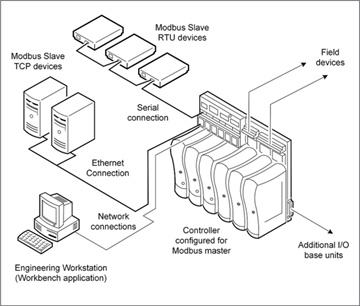
In this example, the
Modbus
RTU slave devices are connected to one or more serial ports on the controller; a common arrangement uses multi-drop (RS-485). In the example, the engineering workstation and the Modbus
TCP slave devices are connected to Ethernet ports on different networks. These devices can also be combined to use the same network.Set up an individual list of messages (commands) for each slave device.
Modbus
read commands cause data to be read from the slave device to the Modbus
master, while Modbus
write commands cause data to be copied from the Modbus
master to the slave device. Also define a sequence of broadcast write commands, which a Modbus
master can send to multiple Modbus
RTU slaves without requiring an acknowledgment. The AADvance controller can control and monitor individual Modbus
master objects and their slave links.When selecting a serial or Ethernet connection type, select the required port. A
Modbus
master uses one of two serial ports related to a processor module. When choosing an Ethernet connection, the master uses both ports related to the processor module (for example, the processor slice). Different Modbus
masters can use different connection types and ports. A processor module failure also causes the failure of the
Modbus
communications allocated to that processor. Communication with slaves allocated to different processor modules are unaffected.Define these properties to configure a
Modbus
Master:Property | Description |
|---|---|
Master Connection | Indication of whether the master uses a Serial or Ethernet connection. The default connection type is Serial. |
Port | The serial or Ethernet port used for Modbus communications.For a serial connection, the possible value is one of the following: S1-1, S1-2, S2-1, S2-2, S3-1, or S3-2. For an Ethernet connection, the possible value is one of the following slices: E1-1 and E1-2, E2-1, and E2-2, or E3-1 and E3-2. |
Name | Name of the Modbus master. Possible values are any combination of alphanumeric characters and punctuation including spaces. |
Protocol | When using a serial port, the controller supports Modbus RTU.When using an Ethernet connection, the controller supports Modbus TCP. |
Timeout (ms) | The period of time the Modbus master waits for a response from its slave devices before retrying or assuming that the slave is unavailable. The timeout is common to all slaves configured to a particular master. The Modbus master uses the timeout for each of its configured slaves to determine whether they are still communicating. If a slave does not respond within this period (and a specific number of retries), it is deemed to have failed. The number of retries is defined for individual slave devices. Possible values are 0 to 60000 milliseconds; the default value is 1000 ms. To avoid unexpected behaviors in the processor when using Modbus TCP communications, wait at least 100 ms before attempting to reconnect to the slave device. |
Control Address | The address of a control register. When using a control variable, the Modbus address of the holding register. The application may write the control variable to switch the state of the master.0 = inactive, the Modbus master is disabled; the link is inactive, there is no communication activity, and all slaves are inactive.1 = standby, the Modbus master is forced to operate in standby mode; the link is active but no data is transferred.2 = active, the Modbus master is forced to operate in active mode; the link is active and transfers data.Possible values are 1 to 65536, or 0 to disable; the default value is 0. |
Status Address | The address of a status register (a holding register). The status register, is a UINT returned by the Modbus driver to let the application monitor and act on Modbus master faults.0 = healthy, the Modbus master is operating normally; the link is active and no errors are reported.1 = initializing 2 = error, the Modbus master has an error and is disabled, or is unable to make a link.Possible values are 1 to 65536, or 0 to disable; the default value is 0. |
Message Wait Interval (ms) | Enables AADvance to support legacy Modbus slave devices having slow communication response times. Only serial RTU links are supported. Possible values range from 0 to 65535 milliseconds; the default value is 100 ms. |
Statistics Mode | Indicates the statistics reporting mode for the master. Possible values are: Disabled, the default reporting mode. Last Rate, reports the length of the most recent scan time. Maximum Rate, reports the longest scan time. Average Rate, reports the average scan time. Statistics are reported in hundredths of a second. For the Last Rate, Maximum Rate, and Average Rate reporting modes, specify the Data Address and Reset Address properties. |
Data Address | The holding register of the data variable. The data variable is reported in hundredths of a second. Possible values are 1 to 65536, or 0 to disable; the default value is 0. |
Reset Address | The holding register of the reset variable. Any non-zero value in the reset variable resets the data variable to zero. Possible values are 1 to 65536, or 0 to disable; the default value is 0. |
Comment | Plain text |
All
Modbus
masters defined for a project (Modbus
RTU or Modbus
TCP) function independent of each other. Each master polls its associated slave devices, to send the messages scheduled for the slaves.If a
Modbus
master encounters communication errors to a slave device, the master suspends polling the slave for a length of time. The suspension enables polling other slaves on the same master without pausing for the communications timeout on each cycle. At regular intervals, the controller pings the non-communicating slave. When the slave responds to a ping, the polling of the slave restarts on the next cycle.
TIP:
If the controller receives error messages with the
replies from a slave, the slave remains in the polling cycle since the controller does not
treat error messages as a communication failure.
To define a
Modbus
Master- In theCommunication View, expand the required controller, and then expand theMODBUSelement.TheMODBUS SlaveandMODBUS Masterelements are displayed.
- Right-click theMODBUS Masterelement, and then clickAdd New Master.
- Double-click theMODBUS Masterinstance.TheCommunicationproperty page is displayed with the Master properties.
- In the property page, select the requiredMaster ConnectionandPort, and then define the required properties.
Provide Feedback