Using Modbus Communications
Modbus
CommunicationsThe AADvance controller supports
Modbus®
communications and can act as a Modbus
master or Modbus
slave. A Modbus
master can have Modbus
master slaves. The AADvance controller can use serial or Ethernet ports for Modbus
communications.
TIP:
The AADvance controller does not support the
Modbus
ASCII protocol.The . December 2006. The
Modbus
functionality implemented by the AADvance controller meets this standard: Modbus
Application Protocol Specification, version 1.1bModbus
Organization.To use
Modbus
communications, Modbus
variables for the controller must be mapped. These variables are then used by Modbus
slaves, Modbus
masters, and Modbus
master slaves. When mapping variables, these are mapped as the following types:- Coils
- Discrete Inputs
- Input Registers
- Holding RegistersTIP: 64-bit variables are not supported in Modbus communications. Use 32-bit variables.
The
Modbus
mapping includes the following properties:Name | The name of the variable. |
Data Type | The data type of the variable. |
Direction | The direction of the variable. |
Base Address | The base address of the variable. Possible values range from 1 to 65536; the
default starting address value is 1. |
Allow Modbus Write | For Coils and Holding Registers, indicates whether data can be copied from the
Modbus master to the slave device. |
Modbus
uses a numeric addressing scheme to move data between devices. AADvance controllers provide a dedicated area for each of the four variable types. The original Modbus
standard defines the address field as a four-digit field with a prefix relating to the variable type. The crosshatch areas in the following example display how the original-style, five-digit Modbus
addresses (for example, a holding register at 40,001) are related to the AADvance memory map.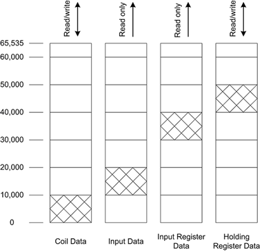
The base addresses used for
Modbus
data transfer listings start at one. The first variable network address of the AADvance controller is 1 and the first coil is 00001. When managing
Modbus
variables, perform these tasks in the Modbus
element:Task | Procedure |
|---|---|
Add a Modbus variable |
|
Renumber base addresses of Modbus variables | Renumber the base addresses of Modbus mapped variables. Base address values are assigned in the order of appearance in the list of mapped variables. Base addresses range from 1 to 65536; the default starting address value is 1.
TIP:
Manually modify the base address of
Modbus variables to the required values.In the Communication View , double-click the Modbus The Communication property page displays.
|
Allow the Modbus write attribute for Modbus variables | Allow the Modbus write attribute for coils and holding registers mapped variables.
|
Disable the Modbus write attribute on Modbus variables | Disable the Modbus® write attribute for mapped variables. The Modbus write attribute is only available for coils and holding registers variables.
|
Remove Modbus variables |
|
Delete a Modbus object |
|
Also configure
Modbus
Master and Slave protocols for use in the communication services for controllers.Provide Feedback