LED Templates for Output Modules
The LED template defines the mapping between the output state and the front panel indicators for the specific module. Use the
LED State Editor
to map the required operation for all output channels. An LED mapping entry is made using the following syntax:state# = <OFF | RED | GREEN [+FLASH]>
If no entries are made in this section, the module will operate with the default LED mapping. The following example displays the default values for the 8451 Digital Output Module, which are suitable for outputs without line monitoring devices installed.
State for Output Modules | State for 8449 Module | Default Value | Description |
|---|---|---|---|
0 | 0 | = Off | Not used |
1 | 1 | = Red | No field supply voltage |
2 | 2 | = Off | Output de-energized |
3 | 3 | = Green | Line open circuit |
4 | 4 | = Green | Output energized (on) |
5 | 5 | = Red | Field short circuit |
6 | 6 | = Off | Not used |
7 | 7 | = Off | Not used |
8 | - | = Red |
TIP:
State 7 represents a module fault. States 8 through 15
all represent channel fault states (except for the 8449 Valve Monitor module). For the 8449
module, states 8 through 15 are used differently since the valve outputs and position inputs
are grouped in pairs.
To configure the color and operating modes of the LED front panel indicators
- From theTemplate Creationdialog box, enter the template name, select an applicableModule Type, then select theLED Template Type, and then clickEdit Template.
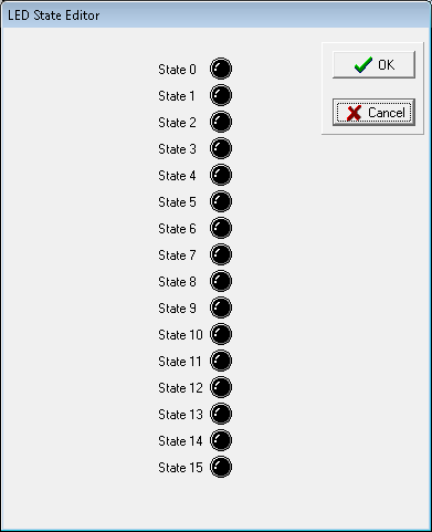 TheLED State Editordisplays.
 - To modify the color and operating mode of the channel, click the required state LED icon, and then click one of these:
- Off
- Red
- Green
- Red Flash
- Green FlashThe modified channel LED of the output module displays.
- In theLED State Editor, configure the required output channel states, and then clickOK.
Provide Feedback