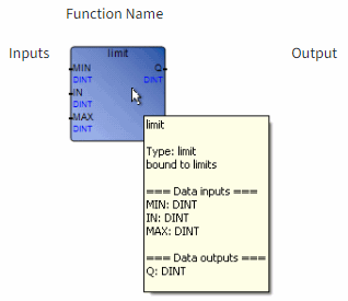
FBD Diagram Main Format
Function Block Diagram (FBD) diagrams describe a process between input
variables and output variables. A process is described as a set of elementary blocks. Input
and output variables are connected to blocks by connection lines. Outputs of blocks can also
be connected to inputs of other blocks.

An entire process represented by an FBD program is built using
the available variables, operators, functions, and function blocks. Each block has either a
fixed or defined number of input and output connection points. A block is represented by a
single rectangle. The inputs are connected on its left border. The outputs are connected on
its right border. An elementary block performs a single function between its inputs and its
outputs. The name of the function to be performed by the block is written inside its
rectangular shape. Each input or output of a block is labeled and has a well-defined
type.

Input
variables of an FBD program must be connected to input connection points of blocks. The type
of each variable must be the same as the type expected for the associated input. An input
for FBD diagram can be a literal, any internal or input variable, an output variable, or a
block output.
Output variables of an FBD program must be connected to output
connection points of blocks. The type of each variable must be the same as the type expected
for the associated block output. An output for FBD diagram can be any internal or output
variable, or the name of the function (for functions only). When an output is the name of
the currently edited function, it represents the assignment of the return value for the
function (returned to the calling program).
Input and output variables, inputs and
outputs of the blocks are wired together with connection lines, or links. Single lines can
be used to connect two logical points of a diagram:
- An input variable and an input of a block
- An output of a block and an input of another block
- An output of a block and an output variable
The connection is oriented, meaning that the line carries associated data from left to
right. The left and right ends of the connection line must be of the same data
type.
Vertical bars accept several connections on the left and several connections on
the right. Each connection on the right is equal to the OR combination of the connections on
the left. All ends of the connections must be of the same data type.
Provide Feedback
