Configure Output Controller
FactoryTalk Analytics GuardianAI can write insights, such as anomalies, failure risks, and other diagnostic information, to a Logix-based controller (ControlLogix or CompactLogix). This integration is achieved using a provided custom UDT (User-Defined Data Type) structure that you can import into the controller using Studio 5000 Logix Designer.
Once FactoryTalk Analytics GuardianAI findings are written to the UDT, any application or system capable of communicating with the controller can access and act on this data. This enables flexible user notifications and integration with both Rockwell and third-party systems. Examples include historizing the data in a historian solution or automatically generating work orders in Rockwell and third-party CMMS (Computerized Maintenance Management Systems).
To accelerate the value of this feature, use the preconfigured HMI faceplates available in Rockwell Automation’s AI Device Library. These faceplates are compatible with FactoryTalk Optix, FactoryTalk View ME/SE, and Studio 5000 View Designer, allowing operators to view diagnostics from the FactoryTalk Analytics GuardianAI system directly on the HMI. For more information, see the AI Device Library Reference Manual DEVICE-RM700 (https://literature.rockwellautomation.com/idc/groups/literature/documents/rm/device-rm700_-en-p.pdf).
The configuration of output controller is optional. To configure the output controller, follow the below steps:
- Select theController profilefrom theWrite controllersection.Alternatively the user can add a new profile using theAdd Profileoption and then the controller profile.To add a profile, follow the below steps:
- In theOutput Controllerpage, clickAdd Profile. TheAdd Controller Profilepop-up window is displayed.
- Provide the following details:
- Controller profile name: Provide a name for the controller profile. This is mandatory.
- Controller path: Provide the path. This is mandatory.Following is an example format for the controller path: *:{Ethernet bridge IP address}/{Chassis port}:{Slot}Example controller path: 2:192.168.1.0/1:0Following is an example where the user can access the controller in chassis 2 from the workstation: 2:192.168.32.10/1:4/2:192.168.32.11/1:0 where:
- 2 is the outgoing port from the workstation.
- 192.168.32.10 is the Ethernet bridge IP address
- 1 is the port number of chassis 1
- 4 is the slot number of chassis 1
- 2 is the outgoing port
- 192.168.32.11 is the Ethernet bridge IP address
- 1 is the port number of chassis 2
- 0 is the slot number of chassis 2
- ClickTest Connection. The "Connection tested successfully." message is displayed.
- ClickAdd. The "Controller Profile successfully added." message is displayed.
Output Controller Illustration
- From theTag selection, select the tag that will be used to communicate with the controller. The tag is the one that contains the custom UDT provided by the FactoryTalk Analytics GuardianAI. To download the custom UDT, follow the instruction given in Download UDT.
- Drag and drop the selected tag to theSelected tagssection.NOTE: If there are nested tags and if UDT tag is not available under a parent tag, <No UDTs found> message is displayed.Output Controller
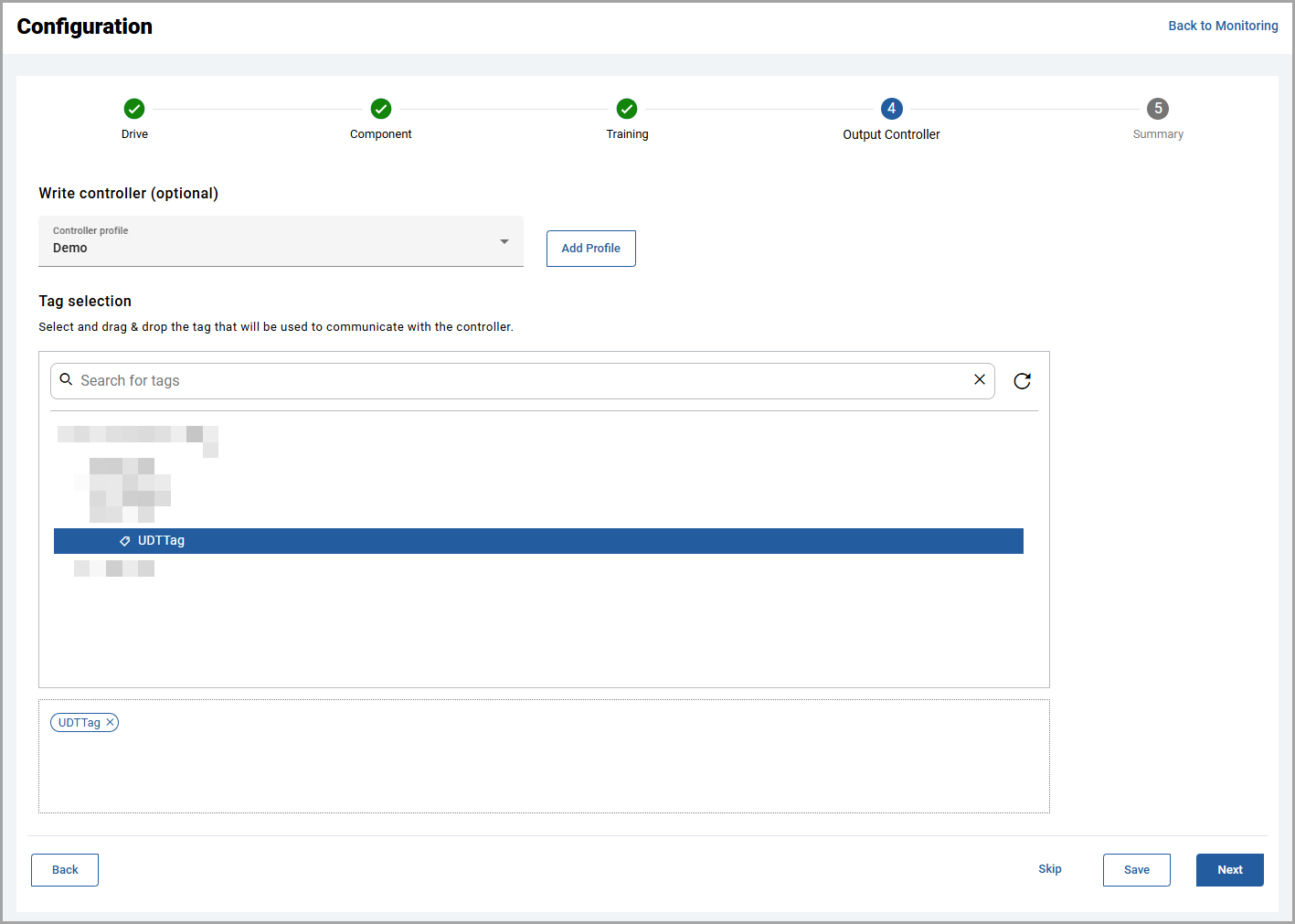
- ClickSave. The "Write controller configuration saved." message is displayed. The selected tag cannot be used again in different drive and hence it will be disabled.
- ClickNextto verify the summary.
Provide Feedback