LD Language
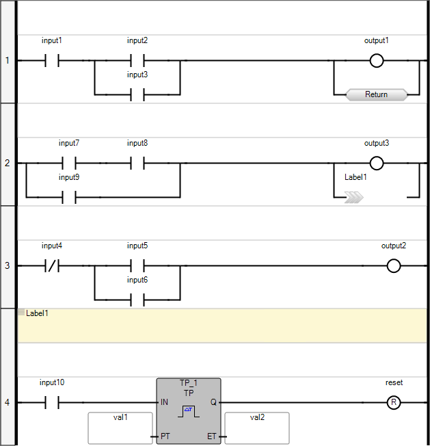
Ladder Diagram (LD) is a graphic representation of Boolean equations, combining contacts
(input arguments) with coils (output results). The LD language enables the description of
tests and modifications of Boolean data by placing graphic symbols into the program chart. LD
graphic symbols are organized within the chart as an electric contact diagram. Thus, the term
"ladder" coming from the concept of rungs connected to vertical power rails at both ends where
each rung represents an individual circuit.
Adjust editor and view settings for individual or all Ladder Diagrams. When working in a
Ladder Diagram, set the properties for the diagram from the Container properties in the
Properties window. Set the properties for all Ladder Diagrams using the options available from
the
Tools
menu. Some of the available properties include:- background and gradient colors for operators, functions, and function blocks
- displaying the grid and the height and width of grid cells, in pixels
- height and width of elements, in grid cells. Basic elements are blocks without inputs or outputs, coils, and contacts. For blocks, each input and output adds a basic element dimension. For example, note the contact using the default settings of one grid cell high by four grid cells wide. The following block uses a basic element width for the inputs, another for the block, and another for the outputs. The block uses a basic element height for the EN/ENO level, another for the first input and the output, and another for the second input.
- font type, size, style, and color applied to the text displayed in elements
- various options such as displaying comments and labels, aligning coils, and setting the colors for variables, labels, comments, power rails, and rung headers
Provide Feedback