Defining Ethernet Ports
The AADvance controller provides up to six Ethernet communication ports, two for each 9110 processor module present. Each pair of Ethernet ports is identified as E
n
-1 and En
-2 where n
indicates the processor module.- [E1-1 and E1-2]
- [E2-1 and E2-2]
- [E3-1 and E3-2]
The E
n
-1 Ethernet ports are all on one network and the En
-2 ports are on a second network.
TIP:
To avoid unexpected ARP requests, it is recommended to
configure IP addresses for E
n
-2 ports (even if they are unused).When defining Ethernet ports, indicate an IP address and optionally a comment. Each controller on a local area network must have a unique IP address. Set the IP address when creating a system or fitting a new processor base unit. The IP address must be configured in the physical controller by using AADvance Discover and must then be configured in the AADvance controller.
TIP:
Change an IP address in the
Communication
property page only. Changing an IP address in the Properties
window does not update
the IP address in Communication View
.To define Ethernet ports
- From theAADvance-Trusted SIS Workstation software, open or create the required project.
- From theViewmenu, clickCommunication View.
- In theCommunication View, right-clickEthernet, and then clickOpen.
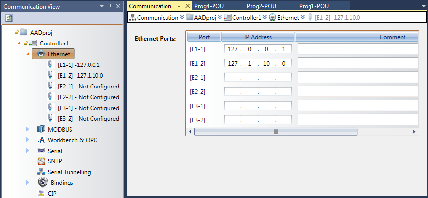 The Communication property page displays with the six Ethernet Ports.
 - In theCommunicationproperty page, type the IP address for each required port.TIP: Ports that are Not Configured can be configured individually by selecting the required port in theCommunication View.
Provide Feedback