Configuring I/O Modules for Trusted Applications
Trusted
ApplicationsAfter assigning modules to their required slots in the
Trusted
chassis, all I/O modules for the Trusted
system must be configured. When configuring the I/O module, the Module Definition
dialog box displays the supported templates to add to the definition. Templates must be created before adding them to the I/O module definition. Scheduled polling, simulation, and a description for the module ay also be enabled.When enabling scheduled polling, specify the following parameters:
Parameter | Definition | |
|---|---|---|
Poll Interval | The scan rate of the I/O module. Possible values range from o to 20. For example, a value of 5 means the I/O module is only scanned every 5 application scans. | |
Poll Offset | Defines the application scan that scans the I/O module, enabling an even distribution of scans. The offset value must be less than the defined Poll Interval. For example, if two modules have the Poll Interval set to 5, and one has the Poll Offset set to 3 and the other to 4, the first module is polled in the third scan and the other is polled in the fourth scan, so that they do not get polled in the same application scan. | |
TIP:
All input information that is used for safety-critical
functions must have an update rate less than one-half the Process Safety Time.
Enabling simulation allows the system to start up without the primary module installed. Software simulation of the module is invoked if the module is not present. Simulation provides a set of default values for the field inputs corresponding to the default safe-state (logic ‘0’). If the module is present the system uses the actual module instead of the simulation model. Simulation is useful during system integration as it allows the normal applications to be loaded and tested without a full complement of I/O modules.
When simulating, the
Partner Chassis
and Partner Slot
must be specified for the System to start without the primary module fitted. The secondary module position must always be the adjacent slot to the right of that occupied by the primary module when using the Companion Slot configuration. When starting up a system with a secondary module, the simulation model is first opened (inputs signals all report default safe-state) and the system performs an Active/Standby changeover between the simulated model and the actual secondary module.The
Partner Chassis
and Partner Slot
parameters are used to identify the position for a unique Companion Slot position for a standby module. The Partner Chassis
and Partner Slot
parameters should not be specified for a SmartSlot system since more than one module may use the same smart slot. If the same partner chassis/slot is specified for different modules, the MP removes the partnering. Therefore, SmartSlot systems should have Partner Chassis
and Partner Slot
set to 0.
TIP:
For Companion Slot modules, enter a module in the
primary slot. Enable simulation and enter the partner (secondary) chassis and slot location.
Do NOT enter a module in the secondary slot.
To configure an I/O module
- From theSystem Configuration Tool, in the required chassis, click the I/O module to configure.
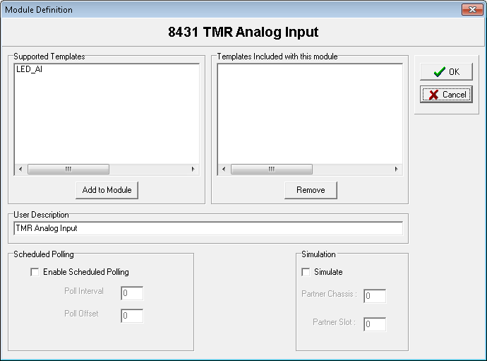 TheModule Definitiondialog box displays for the specific I/O module.
 - In theModule Definitiondialog box, select the required templates in theSupported Templateslist and then clickAdd to Module.The templates display in theTemplates Included with this modulelist.
- To remove a template from the I/O module definition, select the template in theTemplates Included with this modulelist and then clickRemove.
- To enable polling, selectEnable Scheduled Pollingand then enter the required values forPoll IntervalandPoll Offset.
- To enable simulation, selectSimulateand then enter the required values forPartner ChassisandPartner Slot.
- To add a description, type the required information in theUser Descriptiontext box.
- To complete the I/O module configuration, clickOK.
Provide Feedback