Debug LD Programs
When power flow debugging Ladder Diagram (LD) programs, monitor the output values of
elements. These values display using color, numeric, or textual values according to their
data type:
- Output values of Boolean type display using color. The output value color continues to the next input. When the output value is unavailable, Boolean elements remain black. The default colors are red when True and blue when False. Customize the colors used for Boolean items.
- Output values of DINT, REAL, TIME, and MESSAGE type display as a numeric or textual value in the element. When the output is a structure type, the display value is the selected member.
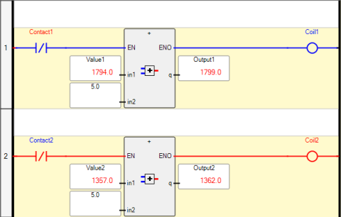
When the output value for a numeric or textual value is unavailable, the
WAIT
text
displays in the output label. Transitional elements like Pulse rising edge (positive)
contacts, with an unstable state, remain black. Values also display in the corresponding
dictionary instance.When the device is in the DEBUGGING state, perform one of these operations:
Task | Procedure | ||
|---|---|---|---|
Change the cycle timing |
| ||
Toggle the logical value of a contact, coil, or block input |
|
 .
.
IMPORTANT:
Set the
Generate debug information
property to False
if a build error occurs when the In-line
property is True
for LD function blocks.Provide Feedback