
Motion Redefine Position (MRP)
Use the Motion Redefine Position (MRP) instruction to change the command or actual
position of an axis. The value specified by Position is used to update the Actual or
Command position of Axis. The position redefinition can be calculated on an Absolute
or Relative basis. If Absolute is selected the Position value is assigned to the
current Actual or Command position. If Relative is selected the Position value is
added as a displacement to the current Actual or Command position. The process of
redefining the current axis position has no affect on motion in progress as the
instruction preserves the current servo following error during the redefinition
process. As a result, axis position can be redefined on-the-fly without disturbing
axis motion.
Available Languages
Ladder Diagram
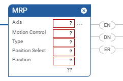
Structured Text
MRP(Axis,MotionControl,Type,PositionSelect,Position);
Operands
Ladder Diagram and Structured Text
Operand | Type | Format | Description |
|---|---|---|---|
Axis | AXIS | Tag | Name of the axis on which to perform the operation. |
Motion Control | MOTION_INSTRUCTION | Tag | Structure used to access instruction parameters. |
Type | BOOLEAN | Immediate | The way you want the redefinition operation to work. Select
either: 0 = absolute 1 = relative |
Position Select | BOOLEAN | Immediate | Choose what position to perform the redefinition operation on.
Select either: 0 = actual position 1 = command position |
Position | REAL | Immediate or Tag | The value to use to change the axis position to or offset to
current position. |
See Structured Text syntax for more information on the syntax of expressions within structured text.
For the operands that require you to select from available options, enter your
selection as:
This Operand | Has These Options Which You | |
|---|---|---|
Enter as Text | Or Enter as a Number | |
Type | Absolute Relative | 0 1 |
PositionSelect | Actual Command | 0 1 |
MOTION_INSTRUCTION Structure
Mnemonic | Description |
|---|---|
.EN (Enable) Bit 31 | It is set when the rung makes a false-to-true transition and
remains set until the servo message transaction is completed and
the rung goes false. |
.DN (Done) Bit 29 | It is set when the axis' position action has been
successfully redefined. |
.ER (Error) Bit 28 | It is set to indicate that the instruction detected an error,
such as if you specified an unconfigured axis. |
Description
The MRP instruction directly sets the actual or command position of the specified
axis to the specified absolute or relative position. No motion is caused by this
instruction—the current axis position is simply redefined. Select or enter the
desired Axis, Type, Position Selection, and enter a value or tag variable for the
desired New Position.
If the targeted axis does not appear in the list of available axes, the axis has not
been configured for operation. Use the Tag Editor to create and configure a new
axis.
The MRP instruction may be used while the axis is moving as well as when it is at
rest. MRP is used to redefine position on-the-fly for certain registration, slip
compensation, and re-calibration applications.
Selection | Description |
|---|---|
Absolute Mode | When Absolute is selected or entered as the MRP Type, the New
Position specifies the new absolute position of the axis. No
motion occurs—the current axis position (actual or command) is
simply redefined to be the specified new position. If software overtravel limits are used, the new position must be
between the Max Positive and Max Negative Travel configuration
values. Otherwise a software overtravel fault is generated when
the instruction is executed. Important : If software overtravel limit checking is in
effect, execution of an MRP in Absolute Mode may invalidate the
current Max Positive and Max Negative Travel limits in the
absolute sense. Exercise caution when redefining the absolute
position of an axis that has travel limits.Absolute and relative mode MRP instructions have the same effect
when the axis is not moving. When the axis is moving, however,
absolute mode introduces a position error equal to the motion of
the axis during the time it takes to execute the MRP instruction
and assign the new position. Relative mode does not introduce
this error and guarantees an exact correction independent of
axis speed or position. |
Relative Mode | When Relative is selected or entered as the MRP Type, the New
Position value is used to offset the current position of the
axis. No motion occurs—the current axis position (actual or
command) is simply redefined to be the current position plus the
specified new position. In relative mode, axis position is redefined in such a way that
no position errors are introduced if the axis is moving. It is
particularly useful for unwinding axis position under program
control rather than using the built-in rotary axis feature. Absolute and relative mode MRP instructions have the same effect
when the axis is not moving. When the axis is moving, however,
absolute mode introduces a position error equal to the motion of
the axis during the time it takes to execute the MRP instruction
and assign the new position. Relative mode does not introduce
this error and guarantees an exact correction independent of
axis speed or position. |
Actual Position | When Actual is selected or entered as the MRP Position Selection,
the New Position is directly applied to the actual position of
the physical axis. The command position of the axis is also
adjusted along with the new actual position to preserve any
position error which exists. This ensures that there is no
unexpected motion of the axis when the positions are redefined.
See the Motion Axis Object Specification for more discussion of
command position, actual position, and position error. |
Command Position | When Command is selected or entered as the MRP Position
Selection, the New Position is directly applied to the command
position of the servo or imaginary axis. For an axis with a
Position Loop type of Feedback Only, the Command Position and
the Actual Position are the same. The MRP can be used with ether
the Command or Actual Position with the same effect. The actual
position of servo axes is also adjusted along with the new
command position to preserve any position error which exists.
This ensures that there is no unexpected motion of the axis when
the positions are redefined. Command position is the desired or commanded position of a servo
as generated by any previous motion instructions. Actual
position is the current position of a physical or virtual axis
as measured by the encoder or other feedback device. Position
error is the difference between these two and is used to drive
the motor to make the actual position equal to the command
position. The Figure below shows the relationship of these three
positions. 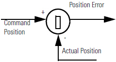 To successfully execute a MRP instruction, the targeted axis must
be configured as either a Servo or Feedback Only axis.
Otherwise, the instruction errs. Important : The instruction execution may take multiple
scans to execute because it requires multiple coarse updates to
complete the request. The Done (.DN) bit is not set immediately,
but only after the request is completed. |
In this transitional instruction, the relay ladder, toggle the Rung-condition-in from
cleared to set each time the instruction should execute.
Affects Math Status Flags
No
Major/Minor Faults
None specific to this instruction. A major fault can occur if an uninitialized
reference or a reference of incorrect type is passed to the Axis Operand. See Common Attributes for operand-related faults.
Execution
Ladder Diagram
Condition/State | Action Taken |
|---|---|
Prescan | The .EN, .DN, .ER, and .IP bits are cleared to false. |
Rung-condition-in is false | The .EN bit is cleared to false if the .DN or .ER bit is
true. |
Rung-condition-in is true | The .EN bit is set to true and the instruction executes. |
Postscan | N/A |
Structured Text
Condition/State | Action Taken |
|---|---|
Prescan | See Prescan in the Ladder Diagram table. |
Normal execution | See Rung-condition-in is false, followed by rung is true in the
Ladder Diagram table. |
Postscan | See Postscan in the Ladder Diagram table. |
Error Codes
See Motion Error Codes
.ERR for Motion Instructions.
Extended Error Codes
Extended Error Codes provide additional instruction specific information for the
Error Codes that are generic to many instructions. See Motion Error Codes
.ERR for Motion Instructions. The following Extended Error codes help to
pinpoint the problem when the MRP instruction receives a Servo Message Failure (12)
error message.
Associated Error Code (decimal) | Extended Error Code (decimal) | Meaning |
|---|---|---|
SERVO_MESSAGE_FAILURE (12) | Device in wrong state (16) | Redefine Position, Home, and Registration 2 are mutually
exclusive. |
Extended Error codes for the Parameter Out of Range (13) error code work a little
differently. Rather than having a standard enumeration, the number that appears for
the Extended Error code refers to the number of the operand as they are listed in
the faceplate from top to bottom with the first operand being counted as zero.
Therefore for the MRP instruction, an extended error code of 4 would refer to the
Position operand’s value. You would then have to check your value with the accepted
range of values for the instruction.
MRP Changes to Single Axis Status Bits
The AxisHomedStatus bit is not impacted by the execution of the MRP instruction. The
status is the same before and after the MRP is execution. If the axis has been homed
using the absolute home procedure, the AbsoluteReferenceStatus is set.
AxisHomedStatus may also be set is the axis has not been subject to a power cycle.
AbsoluteReferenceStatus is cleared when the MRP is executed and this is only true to
Axis_Servo_Drive axis. This indicates the axis position is no longer referenced to
the absolute home position.
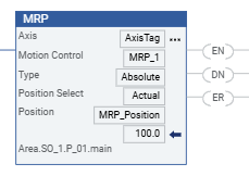
Example
Ladder Diagram
Provide Feedback