
Motion Axis Gear (MAG)
The Motion Axis Gear (MAG) instruction provides electronic gearing between any two
axes in a specified direction and at a specified ratio. When called, the specified
Follower Axis is geared to the Leader Axis at the specified Ratio (for example,
1.345) or Follower Counts to Leader Counts (for example, 1:3). The MAG instruction
supports specification of the gear ratio in one of two different formats, Real or
Fractional, as determined by the Ratio Format input selection. The direction of
Follower Axis motion relative to the Leader Axis is defined by a very flexible
Direction input parameter. The gearing direction may be explicitly set as the Same
or Opposite or set relative to the current gearing direction as Reverse or
Unchanged.
TIP:
The value for Ratio is sign sensitive. The Leader
Reference selection allows gearing input to be derived from either the Actual or
Command position of the Leader Axis. When the instruction’s Clutch capability is
activated the gearing instruction commands the follower axis to accelerate or
decelerate at a controlled rate before Locking on to the leader axis using the
instructions Acceleration value much like the clutch of a car.
This is a transitional instruction. Follow these steps when using it:
- In ladder logic, insert an instruction to toggle the rung-condition-in from false to true each time the instruction should execute.
- In a Structured Text routine, insert a condition for the instruction to cause it to execute only on a transition.
Available Languages
Ladder Diagram
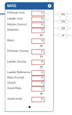
Structured Text
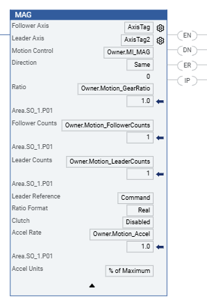
MAG(FollowerAxis,LeaderAxis,MotionControl,Direction,Ratio,FollowerCounts,LeaderCounts,LeaderReference,RatioFormat,Clutch,AccelRate,AccelUnits);
Operands
Ladder Diagram and Structured Text
Operand | Type | Format | Description |
|---|---|---|---|
Follower Axis | AXIS | Tag | Name of the axis on which to perform operation. |
Leader Axis | AXIS | Tag | The axis that the follower axis follows. For controllers that support the REF_TO motion data types, the
supported axis operand type can be replaced by an equivalent
REF_TO type. |
Motion Control | MOTION_INSTRUCTION | Tag | Structure used to access instruction status parameters. |
Direction | SINT, INT, or DINT | Immediate | The relative direction that the Follower axis tracks the Leader
Axis. Select one of following: 0 = follower axis moves in the same direction as the leader
axis 1 = follower axis moves in the opposite direction of its current
direction 2 = follower axis reverses from current or previous 3 = follower axis to continue its current or previous
direction. |
Ratio | REAL | Immediate or Tag | Signed Real value establishing the gear ratio in Follower User
Units per Leader User Unit. |
Follower Counts | SINT, INT, or DINT | Immediate or Tag | Integer value representing follower counts used in specifying a
Fractional gear ratio. |
Leader Counts | SINT, INT, or DINT | Immediate or Tag | Integer value representing leader counts used in specifying a
Fractional gear ratio. |
Leader Reference | BOOLEAN | Immediate | Sets the leader position reference to either Command position or
Actual position. 0 = Actual – follower axis motion is generated from the current
position of the leader axis as measured by its encoder or other
feedback device. 1 = Command – follower axis motion is generated from the desired
or commanded position of the leader axis. |
Ratio Format | BOOLEAN | Immediate | The desired ratio specification format. Select either: 0 = real gear ratio 1 = integer fraction of follower encoder counts to leader encoder
counts. |
Clutch | BOOLEAN | Immediate | When Clutch is enabled, motion control ramps the follower axis up
to gearing speed at the instruction’s defined Acceleration
value. If not enabled, the Follower axis immediately locks onto
the Leader axis. If the Leader Axis is currently moving this
condition results in an abrupt uncontrolled acceleration event
of the Follower Axis which can cause the axis to fault. Select
either: 0 = enabled 1 = disabled |
Accel Rate | REAL | Immediate or Tag | Acceleration rate of the Follower Axis in % or Acceleration
Units. It is applied when the Clutch feature is enabled. |
Accel Units | DINT | Immediate | The units used to display the Acceleration value. Select
either: 0 = units per sec 2 1 = % of maximum acceleration |
See Structured Text syntax for more information on the syntax of expressions within structured text.
For the operands that require you to select from available options, enter your
selection as described below.
This Operand | Has These Options Which You | |
|---|---|---|
Enter as Text | Or Enter as a Number | |
LeaderReference | actual command | 0 1 |
RatioFormat | real fraction_follower_leader_counts | 0 1 |
Clutch | enabled disabled | 0 1 |
AccelUnits | unitspersec2 %ofmaximum | 0 1 |
MOTION_INSTRUCTION Structure
Mnemonic | Description |
|---|---|
.EN (Enable) Bit 31 | It is set when the rung makes a false-to-true transition and
remains set until the servo message transaction is completed and
the rung goes false. |
.DN (Done) Bit 29 | It is set when axis gear has been successfully initiated. |
.ER (Error) Bit 28 | It is set to indicate that the instruction detected an error,
such as if you specified an unconfigured axis. |
.IP (In Process) Bit 26 | It is set on positive rung transition and cleared if either
superseded by another Motion Gear Axes command, or terminated by
a stop command, merge, shutdown, or servo fault. |
Description
The MAG instruction enables electronic gearing between two axes at a specified ratio.
Electronic gearing allows any physical axis to be synchronized to the actual or
command position of another physical axis at a precise ratio. It provides a direct
edge-to-edge lock between the two axes—no maximum velocity, acceleration, or
deceleration limits are used. The speed, acceleration, and deceleration of the
follower axis is completely determined by the motion of the leader axis and the
specified gear ratio.
IMPORTANT:
The maximum velocity, acceleration, or
deceleration limits established during axis configuration do not apply to electronic
gearing.
Select or enter the desired Leader Axis, Follower Axis, and Direction and enter a
value or tag variable for the desired ratio. If an axis is dimmed (gray) or not
shown in the Follower Axis pop-up menu, the physical axis is not defined for Servo
operation.
If the targeted axis does not appear in the list of available axes, the axis has not
been configured for servo operation. Use the Tag Editor to create and configure a
new axis.
Electronic gearing remains active through any subsequent execution of jog, or move
processes for the follower axis. This allows electronic gearing motions to be
superimposed with jog, or move profiles to create complex motion and
synchronization.
Slaving to the Actual Position When Actual Position is entered or selected as the
Leader Reference source, the follower axis motion is generated from the actual
position of the leader axis as shown below.
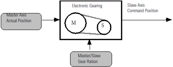
Actual position is the current position of a physical axis as measured by the axis
encoder. This is the only valid selection when the leader axis’ Axis Type is
configured as Feedback Only.
Follower to the Command Position
When Command Position is entered or selected as the Leader Reference source, the
follower axis motion is generated from the command position of the leader axis as
shown below.
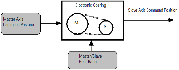
Command position (only valid when the leader axis’ Axis Type is configured as Servo)
is the current desired or commanded position for the leader axis.
Since the command position does not incorporate any associated following error,
external position disturbances, or quantization noise, it is a more accurate and
stable reference for gearing. When gearing to the command position of the leader,
the leader axis must be commanded to move to cause any motion on the follower
axis.
Gear in the Same Direction
When Same is selected or entered as the Direction, the follower axis moves in its
positive direction at the specified gear ratio when the leader axis moves in its
positive direction and vice-versa.
Gear in the Opposite Direction
When Opposite is selected or entered as the Direction, the follower axis moves in its
negative direction at the specified gear ratio when the leader axis moves in its
positive direction and vice-versa.
Change the Gear Ratio
When Unchanged is selected or entered as the Direction, the gear ratio may be changed
while preserving the current gearing direction (same or opposite). This is useful
when the current direction is not known or not important.
Reverse the Gearing Direction
When Reverse is selected or entered as the Direction, the current direction of the
electronic gearing is changed from same to opposite or from opposite to same. This
is very useful for winding applications where the gear ratio must be reversed at
each end of the wind.
Real Number Gear Ratio
When Ratio Format is selected or entered as Real, the gear ratio is specified as a
real number or tag variable with a value between 0.00001 and 9.99999 (inclusive)
representing the desired ratio of follower axis position units to leader axis
position units. A gear ratio expressed this way is easy to interpret since it is
defined in the axes’ configured position units.
Fraction Gear Ratios
When Ratio Format is selected or entered as Fraction, the gear ratio is specified as
a pair of integer numbers or tag variables representing the ratio between the number
of follower axis feedback counts and the number of leader axis feedback counts. See
The Tag variable Builder earlier in this manual for information on tag
variables.
IMPORTANT:
The Conversion Constant entered as part of
the axis configuration procedure is not used when the Ratio Format for the MAG
instruction is specified as a Fraction.
If your gear ratio cannot be exactly expressed as a real number with a maximum of
five digits to the right of the decimal point, use Fraction as the Ratio Format.
Specifying the gear ratio as a fraction allows the direct implementation of
irrational gear ratios (such as 1/3) with no accumulated positioning errors or round
off. Since the leader and follower count values do not use the axis conversion
constants and because they are integers, the actual gear ratio relationship between
the follower and leader axes exactly match the specified ratio.
For example, the irrational gear ratio of 1/3 can be equivalently specified as 1
follower count to 3 leader counts, 10 follower counts to 30 leader counts, 3
follower counts to 9 leader counts.
Clutch
When the Clutch check box is checked, the follower axis accelerates or decelerates to
the speed that it would be moving if it were currently geared to the selected leader
axis at the specified gear ratio and direction using a trapezoidal velocity profile
(linear acceleration or deceleration). Once the follower axis has reached the
gearing speed, electronic gearing is automatically activated according to the other
selections. Enter the desired Accel Rate as a percentage of the current configured
maximum acceleration value or directly in the configured user units for
acceleration.
This clutch function works much like the clutch in a car, allowing the follower axis
to be smoothly engaged to the leader axis as shown below.
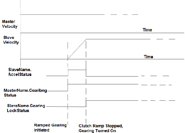
Clutch Function
Using the clutch feature avoids the uncontrolled acceleration or deceleration that
results when electronic gearing is enabled while the leader axis is moving. The
clutch feature can also be used to merge gear ratio changes on-the-fly, even changes
in direction. The motion controller automatically ramps the follower axis to the
speed implied by the leader axis at the new ratio and/or direction.
The operation of the clutch ramp generator has no affect on jog or move processes
that might be in progress on the follower axis.
Changing Leader Axes
The leader axis for electronic gearing can be changed at any time, even while gearing
is currently enabled. However, since it is possible to have electronic gearing
enabled on more than one axis at a time, if a Servo leader axis and follower axis
are reversed, the axes become cross-coupled and unexpected motion may result.
For example, if you are gearing Axis 0 to Axis 1 (defined as a Servo axis) and then
want to change to gearing Axis 1 to Axis 0, you must first disable gearing on Axis 0
(see Disable Gearing later in this section). This is because specifying Axis 1 as
the follower axis with Axis 0 as the leader axis does not automatically disable Axis
0 from being a follower axis with Axis 1 as the leader axis.
Move While Gearing
An incremental MAM instruction may be used for the follower axis (or leader axis if
the Axis Type is configured as Servo) while the electronic gearing is enabled. This
is particularly useful to accomplish phase advance/retard control. The incremental
move distance can be used to eliminate any phase error between the leader and the
follower, or to create an exact non-zero phase relationship. Incremental MAM
instruction may also be used in conjunction with electronic gearing to compensate
for material slip.
Normally a gear ratio of 1 is used with phase adjustment. A 1:1 ratio ensures that
the computed phase error does not change before performing the move to correct it.
Electronic gearing is not normally used with absolute moves, since the ultimate
endpoint is not predictable.
To successfully execute a MAG instruction, the targeted axis must be configured as a
Servo Axis Type and the axis must be in the Servo On state. If any of these
conditions are not met than the instruction errors.
IMPORTANT:
The MAG instruction execution completes in a single scan, thus the Done (.DN) bit
and the In Process (.IP) bit are set immediately. The In Process (.IP) bit
remains set until the initiated Gear process is superseded by another MAG
instruction, or terminated by a Motion Axis Stop command, Merge operation, or
Servo Fault Action.
In this transitional instruction, the relay ladder, toggle the Rung-condition-in from
cleared to set each time the instruction should execute.
Affects Math Status Flags
No
Major/Minor Faults
None specific to this instruction. A major fault can occur if an uninitialized
reference or a reference of incorrect type is passed to the Axis operand. See Common Attributes for operand-related faults
Execution
Ladder Diagram
Condition/State | Action Taken |
|---|---|
Prescan | The .EN, .DN, .ER, and .IP bits are cleared to false. |
Rung-condition-in is false | The .EN bit is cleared to false if either the .DN or .ER bit is
true. |
Rung-condition-in is true | The .EN bit is set to true and the instruction executes. |
Postscan | N/A |
Structured Text
Condition/State | Action Taken |
|---|---|
Prescan | See Prescan in Ladder Diagram table |
Normal execution | See Rung-condition-in is false, followed by rung is true in the
Ladder Diagram table. |
Postscan | See Postscan in Ladder Diagram table. |
Extended Error Codes
Use Extended Error Codes (.EXERR) for more instructions about an error. See Motion Error Codes
.ERR.
If ERR is | And EXERR is | Then | ||
|---|---|---|---|---|
Cause | Corrective Action | |||
13 | Varies | An operand is outside its range. | The EXERR is the number of the operand that is out of range. The
first operand is 0. For example, if EXERR = 4, then check the Decel Rate. | |
EXERR | Operand | |||
10 | Accel Rate | |||
Example
Ladder Diagram
Provide Feedback