HSCE_CFG_PLS
The HSCE_CFG_PLS instruction is used for HSC configuration with Programmable Limit Switch (PLS). This function is an additional set of operating modes for the high-speed counter. When operating in these modes, the preset and output data values are updated using user-supplied data each time one of the presets is reached. These modes are programmed by providing a PLS file that contains the data sets to be used.
Languages supported: Function block diagram, ladder diagram, structured text.
This instruction applies to the L20E, L50E, and L70E controllers.
HSCE_CFG_PLS
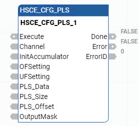
Parameter | Parameter Type | Data Type | Description |
|---|---|---|---|
Execute | Input | BOOL | Rising edge initiates the HSC configuration (HSCE Enable should be equal to FALSE). A falling edge will clear all the output value. |
Channel | Input | HSCE_CHANNEL | The HSCE channel. |
InitAccumulator | Input | LINT | Accumulator initial value. |
OFSetting | Input | LINT | Counter overflow limit value. |
UFSetting | Input | LINT | Counter underflow limit value. |
PLS_Data | Input | PLS2 | Configuration values for High Preset (LINT), Low Preset (LINT), High Preset Output (UDINT), and Low Preset Output (UDINT). |
PLS_Size | Input | USINT | PLS data size, and the maximum value is 24 for a plug-in. |
PLS_Offset | Input | USINT | Offset to start with in the PLS data array. |
OutputMask | Input | UDINT | Output mask for PLS functionality. |
Done | Output | BOOL | HSC configuration action (initiated by this instruction) succeeds. |
Error | Output | BOOL | Indicates that an error occurred. |
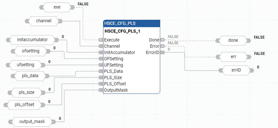
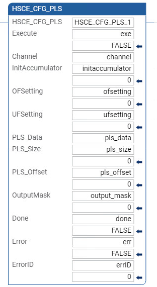
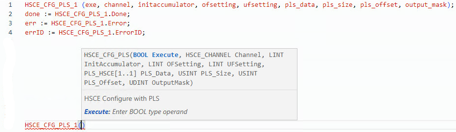
HSCE_CGF_PLS examples
HSCE_CGF_PLS function block diagram example
HSCE_CGF_PLS ladder diagram example
HSCE_CGF_PLS text structure example
Provide Feedback