
Configure the Supplemental Power Tap
Follow these steps to configure the power tap.
- In an existing controller project, select theEtherNet/IP™interface, then add the gateway in the Select Module Type window that follows.Add an 1834-SUP-PWR Supplemental Power Tap
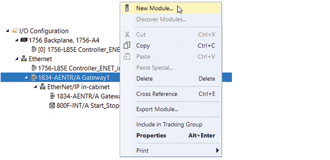 Example: Select a Module
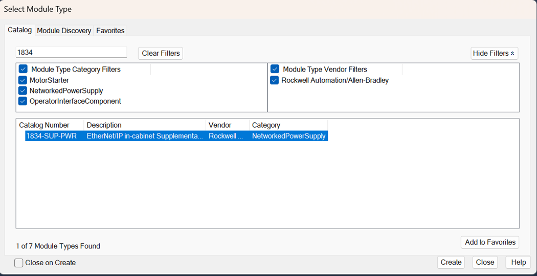 The New Module dialog box contains Information views and Configuration views. The Overview view is where you enter the device definition parameters.
 - For a new device, enter the Device Definition parameters.Supplemental Power Tap Device Definition
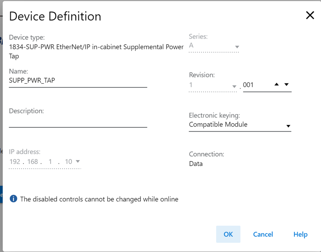 FieldDescriptionDevice typeStatic field that displays the connected device type.NameA text field for a user-defined name.DescriptionThe selected device description is automatically entered.IP addressThis field configures the IP address. Select the final digits of the IP address from the dropdown list. Values are from 2 to 40.SeriesSelect the letter designation for the device series from the dropdown list.RevisionSelect the major and minor revisions from the dropdown lists.Electronic keyingConfigures the type of electronic keying that is used to compare the device in the project with physical device before I/O communication begin. Select the electronic keying type from the dropdown list. Values are:
- Exact Match: Prevents communication if one of the following parameters do not match:
- Vendor ID
- Device Type
- Product Code
- Revision
- Compatible Module: Communication occurs if the following parameters match:
- Vendor ID
- Device Type
- Product Code
- Disable Keying: Communication occurs regardless of whether the keying parameters match or not.
ConnectionSelect the connection for the configured device:- Data
Provide Feedback