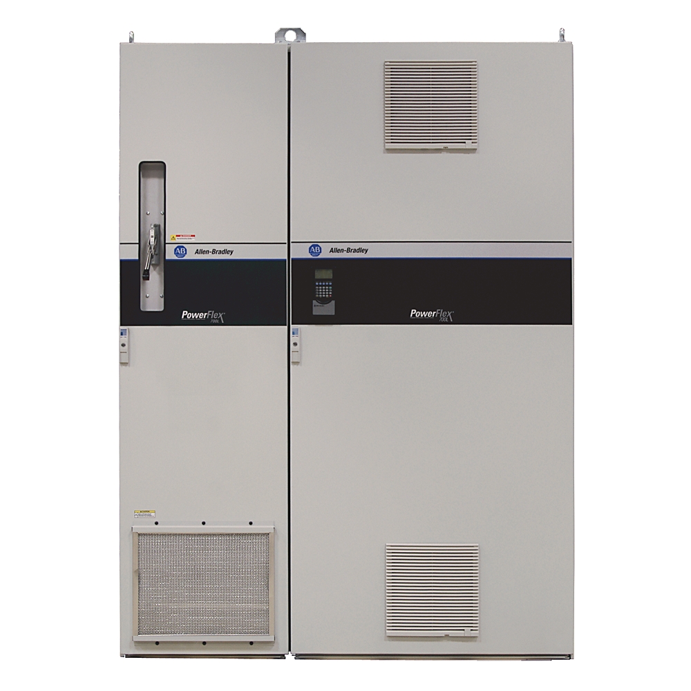
PowerFlex 700L AC Drive 20L
PowerFlex 700L AC Drive 20L
| Unique Product Identifier |
20LC1K2A0ENNAN10WA
|
|---|---|
| UPC |
820919753862
|
| Estimated Lead Time |
43 days
|
| Standard Warranty Duration |
1 year See details |
| Country of Origin |
United States of America
|
| Brake IGBT |
Without
|
|---|---|
| Brake Resistor |
No Internal
|
| Equipment Type |
Complete Regenerative Drive
|
| Feedback Options |
No ftdback
|
| Internal Communication Module |
No Communication Module
|
| Sub Brand |
PowerFlex 700L AC Drive
|
| AC input overvoltage trip |
528V @ 400V
|
|---|---|
| AC input undervoltage trip |
340V @ 400V
|
| Acceleration/deceleration |
Two independently progmable accel and decel times. Each time can be progmed from 0...3600 s in 0.1 s increments
|
| Actual short circuit rating |
Determined by AIC rating of installed circuit breaker.
|
| Additional configuration |
None
|
| Application in domestic- and commercial area permitted |
True
|
| Application in industrial area permitted |
True
|
| Brake IGBT |
No brake IGBT
|
| Brake resistor |
No internal brake resistor
|
| Bussmann fuse current rating |
2000A @ 540V DC
|
| Carrier frequency |
2 or 4 kHz drive rating based on 4 kHz
|
| Circuit breaker current rating |
1500A @ 400...480V AC input voltage
|
| Control logic noise immunity |
Showering arc transients upto 1500V peak
|
| Control method |
Sine coded PWM with progmable carrier frequency
|
| Control options |
700 vector control with 24V DC I/O
|
| Current limit capability |
Proactive current limit progmable from 20...160% of rated output current, Independently progmable proportional and integral gain
|
| DC bus overvoltage trip |
815V @ 400V
|
| DC bus undervoltage shutoff/fault |
300V @ 400V
|
| DC nominal bus voltage |
600V @ 400V
|
| DC power bus bar |
DC power from converter power module to inverter power module (2 terminals: DC+, DC-) for power terminal
|
| Displacement power factor |
0.98 across entire speed range.
|
| Documentation |
English documentation set
|
| Drive overcurrent trip |
Software overcurrent trip: 200% of rated current (typical)
|
| Efficiency |
97.5% at rated A, nominal line volts
|
| Electronic motor overload protection |
Class 10 motor overload protection according to NEC article 430 and motor over-temperature protection according to NEC article 430.126 (A)(2). UL 508C file E59272
|
| Enclosure type |
IP20/NEMA/UL Type 1
|
| Encoder duty cycle |
50% ±10%
|
| Encoder input voltage supply |
Dual channel plus marker, isolated with differential transmitter output (line drive) incremental, dual channel quadrature type 5V DC or 12V DC (5V DC requires an external power supply), 320 mA/channel for ftdback
|
| Encoder quadrature |
90°, ±27° at 25 °C
|
| Encoder requirements |
Encoders must be line driver type, quadrature (dual channel) or pulse (single channel), 8...15V DC output (3.5...6V DC @ 5V encoder), single-ended or differential and capable of supplying a minimum of 10 mA per channel. Maximum input frequency is 250 kH
|
| Encoder supply |
12V @ 250mA. 12V @ 10mA minimum inputs isolated with differential transmitter, 250 kHz maximum
|
| Encoder type |
Incremental, dual channel
|
| Equipment type |
Complete regenerative drive
|
| Feedback option |
No ftdback
|
| Frequency accuracy |
Digital input: within ±0.01% of set output frequency
|
| Frequency control |
Speed regulation with slip compensation (volts per Hz mode): 0.5% of base speed across 40:1 speed range 40:1 operating range 10 rad/sec bandwidth
|
| Ground fault trip |
Phase-to-ground on drive output
|
| Heat sink thermistor |
Monitored by microprocessor overtemp trip
|
| Human interface module |
No HIM (blank plate inserted)
|
| Input current rating |
1250A @ 540V DC
|
| Input frequency tolerance |
47...63 Hz
|
| Input frequency, ,max |
400 kHz ftdback
|
| Input phases |
3-phase input provides full rating for all drives.
|
| Input power wire lugs |
Input power connections on drive (R/L1, S/L2, T/L3) for power terminal
|
| Input voltage |
400V AC, 3-phase, 60 Hz
|
| Intermittent overload |
110% overload capability for up to 1 min, 150% overload capability for up to 3 s
|
| Internal communication module |
No communication module
|
| Line transients |
Up to 6000 volts peak per IEEE C62.41-1991
|
| Logic control ride-thru |
0.5 s minimum, 2 s typical
|
| Mains frequency |
60 Hz
|
| Mains voltage |
400 V
|
| Number of analogue inputs |
2
|
| Number of analogue outputs |
2
|
| Number of digital inputs |
6
|
| Number of digital outputs |
3
|
| Number of phases input |
3
|
| Number of phases output |
3
|
| Output current (with 400V AC induction motor) |
Normal duty: 1875 A @ 150% of continuous current for 3 s
|
| Output current rating |
1250A @ 960Hp (715 kW) normal duty, 700 Hp (525 kW) heavy duty, frame 3B
|
| Output frequency |
0 to 420 Hz
|
| Output power bus bar |
Motor connections (U/T1, V/T2, W/T3) for power terminal
|
| Output voltage range |
0 to rated motor voltage
|
| Selectable motor control |
Sensorless vector with full tuning. Standard V/Hz with full custom capability and vector control with force technology (with and without ftdback).
|
| Short circuit current rating |
To match specified circuit breaker capability, less than or equal to 200000 A symmetrical.
|
| Short circuit trip |
Phase-to-phase on drive output
|
| Shunt trip rating |
100 kAIC @ 400...480V AC input voltage
|
| Speed control |
Speed regulation with ftdback: 0.001% of base speed across 120:1 speed range 1000:1 operating range 250 rad/sec bandwidth
|
| Stop modes |
Multiple progmable stop modes including RA, Coast, DC-brake, RA-to-hold and S-curve.
|
| Supporting protocol for CAN |
True
|
| Supporting protocol for DeviceNet |
True
|
| Supporting protocol for EtherNet/IP |
True
|
| Supporting protocol for Modbus |
True
|
| Supporting protocol for PROFIBUS |
True
|
| Supporting protocol for TCP/IP |
True
|
| Torque regulation with feedback |
±2%, 2500 rad/sec bandwidth
|
| Torque regulation without feedback |
±5%, 600 rad/sec bandwidth
|
| Watt loss |
Power section: 23000 W 400V total (into air and into liquid)
|
| With control element |
True
|
| Active converter cassette terminal blocks-P1 & P2 |
Active converter AC power and control wiring for control terminal
|
|---|---|
| Custom option |
None
|
| DC bus test point socket |
4 mm socket for DC bus voltage measurement only (2 terminals: DC+, DC-) for power terminal
|
| Depth |
1033 mm
|
| Height |
2278 mm
|
| Motor lead lengths |
76 m (250 ft) total
|
| PE wire lug |
Terminating point for ground wires for power terminal
|
| Recommended tightening torque |
62 Nm (550 in-lb)(±10%), output power bus bar for power terminal
|
| Recommended tightening torque for SHLD terminal |
1.4 Nm (12 in-lb)(±10%) for control terminal
|
| Recommended tightening torque for active converter cassette terminal blocks-P1 & P2 |
0.8 Nm (7 in-lb)(±10%) for control terminal
|
| Recommended tightening torque for terminal blocks-TB5 and TB6 |
1.4 Nm (12 in-lb)(±10%) for control terminal
|
| SHLD terminal |
Terminating point for control wiring shields on power module for control terminal
|
| Terminal blocks-TB5 and TB6 |
Power module control wiring for control terminal
|
| Weight |
1361 kg
|
| Width |
1600 mm
|
| Wire size |
600 MCM to #2 AWG, PE wire lug for power terminal
|
| Wire size for SHLD terminal |
0.3 mm² to 2.1 mm² (#22 AWG to #14 AWG) for control terminal
|
| Wire size for active converter cassette terminal blocks-P1 & P2 |
0.3 mm² to 3.3 mm² (#22 AWG to #12 AWG) for control terminal
|
| Wire size for terminal blocks-TB5 and TB6 |
0.2 mm² to 4 mm² (#24 AWG to #10 AWG) for control terminal
|
| Wire strip length for SHLD terminal |
10 mm (0.39 in) for control terminal
|
| Wire strip length for active converter cassette terminal blocks-P1 & P2 |
8 mm (0.31 in) for control terminal
|
| Wire strip length for terminal blocks-TB5 and TB6 |
8 mm (0.31 in) for control terminal
|
| Degree of protection (IP) |
IP20
|
|---|---|
| PWM frequency |
4 kHz
|
| Shock |
10 G peak for 11 ms duration (±1.0 ms), three shocks in each direction, in each axis
|
| Vibration |
2 mm (0.07 in.) displacement, 1 G peak Alitude, 1 mm (0.04 in.) displacement from 2…13.2 Hz, 0.7 G acceleration at 13.2 Hz to 1.0 G acceleration at 55 Hz, 1 G acceleration from 55 …512 Hz Duration: ten logarithmic sine sweep cycles per axis, at sweep ra
|
| Altitude |
1000 m (3280 ft) at rated current
|
|---|---|
| Atmosphere |
Drive must not be installed in an area where the ambient atmosphere contains volatile or corrosive gas, vapors, or dust, If the drive is not going to be installed for a period of time, it must be stored in an area where it will not be exposed to a corrosi
|
| Coolant flow rating, max |
94.6 l/min
|
| Coolant flow rating, min |
56.8 l/min
|
| Coolant temperature |
0 °C
|
| Coolant type |
WEG50 equals good quality or distilled water with approved inhibited ethylene glycol, 50% glycol by volume or WPG50 equals good quality or distilled water with approved inhibited propylene glycol, 50% glycol by volume.
|
| Degree of protection (NEMA) |
1
|
| Estimated amount of coolant |
19 L
|
| Pressure drop from drive inlet to drive outlet at minimum coolant flow rate |
0.48 bar
|
| Relative humidity |
5...95% noncondensing
|
| Storage temperature |
-40...85 °C (-40...185 °F) for all constructions
|
| Surrounding air temperature without derating, max |
0...40 °C (32...104 °F) @ IP20, NEMA/UL Type 1
|
| Drawings | |
|---|---|
| Dimension Drawing (PDF) | Download (PDF) |
| Product Drawing | Drawing (DXF) |
| Product Drawing | Drawing (DWG) |
| Drawings |
|---|
| Dimension Drawing (PDF) Download (PDF) |
| Product Drawing Drawing (DXF) |
| Product Drawing Drawing (DWG) |
| General | Publication |
|---|---|
| Product Cutsheet | -- |
| Installation Instructions | Publication |
|---|---|
| 20l-in003_-en-e | 20L-IN003 |
| Technical Data | Publication |
|---|---|
| 20l-td001_-en-p | 20L-TD001 |
| 20l-td001_-en-p | 20L-TD001 |
| User Manual | Publication |
|---|---|
| 20l-um001_-en-p | 20L-UM001 |


This product was certified with the above certifications as of 2026-08-11. Products sold before or after this date might carry different certifications. Please review the product label to check for the certifications your specific product carries.
Looking for certification documents?
Explore certifications for this product and more in our comprehensive Literature Library.
| EU Importer Address |
Rockwell Automation N.V |
|---|---|
| EU Authorized Representative Address |
Rockwell Automation N.V |
| Technotes |
|---|
Overview
| Unique Product Identifier |
20LC1K2A0ENNAN10WA
|
|---|---|
| UPC |
820919753862
|
| Estimated Lead Time |
43 days
|
| Standard Warranty Duration |
1 year See details |
| Country of Origin |
United States of America
|
Electrical & Connectivity
| Brake IGBT |
Without
|
|---|---|
| Brake Resistor |
No Internal
|
| Equipment Type |
Complete Regenerative Drive
|
| Feedback Options |
No ftdback
|
| Internal Communication Module |
No Communication Module
|
| Sub Brand |
PowerFlex 700L AC Drive
|
| AC input overvoltage trip |
528V @ 400V
|
|---|---|
| AC input undervoltage trip |
340V @ 400V
|
| Acceleration/deceleration |
Two independently progmable accel and decel times. Each time can be progmed from 0...3600 s in 0.1 s increments
|
| Actual short circuit rating |
Determined by AIC rating of installed circuit breaker.
|
| Additional configuration |
None
|
| Application in domestic- and commercial area permitted |
True
|
| Application in industrial area permitted |
True
|
| Brake IGBT |
No brake IGBT
|
| Brake resistor |
No internal brake resistor
|
| Bussmann fuse current rating |
2000A @ 540V DC
|
| Carrier frequency |
2 or 4 kHz drive rating based on 4 kHz
|
| Circuit breaker current rating |
1500A @ 400...480V AC input voltage
|
| Control logic noise immunity |
Showering arc transients upto 1500V peak
|
| Control method |
Sine coded PWM with progmable carrier frequency
|
| Control options |
700 vector control with 24V DC I/O
|
| Current limit capability |
Proactive current limit progmable from 20...160% of rated output current, Independently progmable proportional and integral gain
|
| DC bus overvoltage trip |
815V @ 400V
|
| DC bus undervoltage shutoff/fault |
300V @ 400V
|
| DC nominal bus voltage |
600V @ 400V
|
| DC power bus bar |
DC power from converter power module to inverter power module (2 terminals: DC+, DC-) for power terminal
|
| Displacement power factor |
0.98 across entire speed range.
|
| Documentation |
English documentation set
|
| Drive overcurrent trip |
Software overcurrent trip: 200% of rated current (typical)
|
| Efficiency |
97.5% at rated A, nominal line volts
|
| Electronic motor overload protection |
Class 10 motor overload protection according to NEC article 430 and motor over-temperature protection according to NEC article 430.126 (A)(2). UL 508C file E59272
|
| Enclosure type |
IP20/NEMA/UL Type 1
|
| Encoder duty cycle |
50% ±10%
|
| Encoder input voltage supply |
Dual channel plus marker, isolated with differential transmitter output (line drive) incremental, dual channel quadrature type 5V DC or 12V DC (5V DC requires an external power supply), 320 mA/channel for ftdback
|
| Encoder quadrature |
90°, ±27° at 25 °C
|
| Encoder requirements |
Encoders must be line driver type, quadrature (dual channel) or pulse (single channel), 8...15V DC output (3.5...6V DC @ 5V encoder), single-ended or differential and capable of supplying a minimum of 10 mA per channel. Maximum input frequency is 250 kH
|
| Encoder supply |
12V @ 250mA. 12V @ 10mA minimum inputs isolated with differential transmitter, 250 kHz maximum
|
| Encoder type |
Incremental, dual channel
|
| Equipment type |
Complete regenerative drive
|
| Feedback option |
No ftdback
|
| Frequency accuracy |
Digital input: within ±0.01% of set output frequency
|
| Frequency control |
Speed regulation with slip compensation (volts per Hz mode): 0.5% of base speed across 40:1 speed range 40:1 operating range 10 rad/sec bandwidth
|
| Ground fault trip |
Phase-to-ground on drive output
|
| Heat sink thermistor |
Monitored by microprocessor overtemp trip
|
| Human interface module |
No HIM (blank plate inserted)
|
| Input current rating |
1250A @ 540V DC
|
| Input frequency tolerance |
47...63 Hz
|
| Input frequency, ,max |
400 kHz ftdback
|
| Input phases |
3-phase input provides full rating for all drives.
|
| Input power wire lugs |
Input power connections on drive (R/L1, S/L2, T/L3) for power terminal
|
| Input voltage |
400V AC, 3-phase, 60 Hz
|
| Intermittent overload |
110% overload capability for up to 1 min, 150% overload capability for up to 3 s
|
| Internal communication module |
No communication module
|
| Line transients |
Up to 6000 volts peak per IEEE C62.41-1991
|
| Logic control ride-thru |
0.5 s minimum, 2 s typical
|
| Mains frequency |
60 Hz
|
| Mains voltage |
400 V
|
| Number of analogue inputs |
2
|
| Number of analogue outputs |
2
|
| Number of digital inputs |
6
|
| Number of digital outputs |
3
|
| Number of phases input |
3
|
| Number of phases output |
3
|
| Output current (with 400V AC induction motor) |
Normal duty: 1875 A @ 150% of continuous current for 3 s
|
| Output current rating |
1250A @ 960Hp (715 kW) normal duty, 700 Hp (525 kW) heavy duty, frame 3B
|
| Output frequency |
0 to 420 Hz
|
| Output power bus bar |
Motor connections (U/T1, V/T2, W/T3) for power terminal
|
| Output voltage range |
0 to rated motor voltage
|
| Selectable motor control |
Sensorless vector with full tuning. Standard V/Hz with full custom capability and vector control with force technology (with and without ftdback).
|
| Short circuit current rating |
To match specified circuit breaker capability, less than or equal to 200000 A symmetrical.
|
| Short circuit trip |
Phase-to-phase on drive output
|
| Shunt trip rating |
100 kAIC @ 400...480V AC input voltage
|
| Speed control |
Speed regulation with ftdback: 0.001% of base speed across 120:1 speed range 1000:1 operating range 250 rad/sec bandwidth
|
| Stop modes |
Multiple progmable stop modes including RA, Coast, DC-brake, RA-to-hold and S-curve.
|
| Supporting protocol for CAN |
True
|
| Supporting protocol for DeviceNet |
True
|
| Supporting protocol for EtherNet/IP |
True
|
| Supporting protocol for Modbus |
True
|
| Supporting protocol for PROFIBUS |
True
|
| Supporting protocol for TCP/IP |
True
|
| Torque regulation with feedback |
±2%, 2500 rad/sec bandwidth
|
| Torque regulation without feedback |
±5%, 600 rad/sec bandwidth
|
| Watt loss |
Power section: 23000 W 400V total (into air and into liquid)
|
| With control element |
True
|
Physical Characteristics
| Active converter cassette terminal blocks-P1 & P2 |
Active converter AC power and control wiring for control terminal
|
|---|---|
| Custom option |
None
|
| DC bus test point socket |
4 mm socket for DC bus voltage measurement only (2 terminals: DC+, DC-) for power terminal
|
| Depth |
1033 mm
|
| Height |
2278 mm
|
| Motor lead lengths |
76 m (250 ft) total
|
| PE wire lug |
Terminating point for ground wires for power terminal
|
| Recommended tightening torque |
62 Nm (550 in-lb)(±10%), output power bus bar for power terminal
|
| Recommended tightening torque for SHLD terminal |
1.4 Nm (12 in-lb)(±10%) for control terminal
|
| Recommended tightening torque for active converter cassette terminal blocks-P1 & P2 |
0.8 Nm (7 in-lb)(±10%) for control terminal
|
| Recommended tightening torque for terminal blocks-TB5 and TB6 |
1.4 Nm (12 in-lb)(±10%) for control terminal
|
| SHLD terminal |
Terminating point for control wiring shields on power module for control terminal
|
| Terminal blocks-TB5 and TB6 |
Power module control wiring for control terminal
|
| Weight |
1361 kg
|
| Width |
1600 mm
|
| Wire size |
600 MCM to #2 AWG, PE wire lug for power terminal
|
| Wire size for SHLD terminal |
0.3 mm² to 2.1 mm² (#22 AWG to #14 AWG) for control terminal
|
| Wire size for active converter cassette terminal blocks-P1 & P2 |
0.3 mm² to 3.3 mm² (#22 AWG to #12 AWG) for control terminal
|
| Wire size for terminal blocks-TB5 and TB6 |
0.2 mm² to 4 mm² (#24 AWG to #10 AWG) for control terminal
|
| Wire strip length for SHLD terminal |
10 mm (0.39 in) for control terminal
|
| Wire strip length for active converter cassette terminal blocks-P1 & P2 |
8 mm (0.31 in) for control terminal
|
| Wire strip length for terminal blocks-TB5 and TB6 |
8 mm (0.31 in) for control terminal
|
| Degree of protection (IP) |
IP20
|
|---|---|
| PWM frequency |
4 kHz
|
| Shock |
10 G peak for 11 ms duration (±1.0 ms), three shocks in each direction, in each axis
|
| Vibration |
2 mm (0.07 in.) displacement, 1 G peak Alitude, 1 mm (0.04 in.) displacement from 2…13.2 Hz, 0.7 G acceleration at 13.2 Hz to 1.0 G acceleration at 55 Hz, 1 G acceleration from 55 …512 Hz Duration: ten logarithmic sine sweep cycles per axis, at sweep ra
|
Compliance & Environment
| Altitude |
1000 m (3280 ft) at rated current
|
|---|---|
| Atmosphere |
Drive must not be installed in an area where the ambient atmosphere contains volatile or corrosive gas, vapors, or dust, If the drive is not going to be installed for a period of time, it must be stored in an area where it will not be exposed to a corrosi
|
| Coolant flow rating, max |
94.6 l/min
|
| Coolant flow rating, min |
56.8 l/min
|
| Coolant temperature |
0 °C
|
| Coolant type |
WEG50 equals good quality or distilled water with approved inhibited ethylene glycol, 50% glycol by volume or WPG50 equals good quality or distilled water with approved inhibited propylene glycol, 50% glycol by volume.
|
| Degree of protection (NEMA) |
1
|
| Estimated amount of coolant |
19 L
|
| Pressure drop from drive inlet to drive outlet at minimum coolant flow rate |
0.48 bar
|
| Relative humidity |
5...95% noncondensing
|
| Storage temperature |
-40...85 °C (-40...185 °F) for all constructions
|
| Surrounding air temperature without derating, max |
0...40 °C (32...104 °F) @ IP20, NEMA/UL Type 1
|
Drawings
| Drawings | |
|---|---|
| Dimension Drawing (PDF) | Download (PDF) |
| Product Drawing | Drawing (DXF) |
| Product Drawing | Drawing (DWG) |
| Drawings |
|---|
| Dimension Drawing (PDF) Download (PDF) |
| Product Drawing Drawing (DXF) |
| Product Drawing Drawing (DWG) |
Documents
|
Product Cutsheet
General
-- |
|
20l-in003_-en-e
Installation Instructions
20L-IN003 |
|
20l-td001_-en-p
Technical Data
20L-TD001 |
|
20l-td001_-en-p
Technical Data
20L-TD001 |
|
20l-um001_-en-p
User Manual
20L-UM001 |
| General | Publication |
|---|---|
| Product Cutsheet | -- |
| Installation Instructions | Publication |
| 20l-in003_-en-e | 20L-IN003 |
| Technical Data | Publication |
| 20l-td001_-en-p | 20L-TD001 |
| 20l-td001_-en-p | 20L-TD001 |
| User Manual | Publication |
| 20l-um001_-en-p | 20L-UM001 |
Downloads
Certifications
This product was certified with the above certifications as of 2026-08-11. Products sold before or after this date might carry different certifications. Please review the product label to check for the certifications your specific product carries.
Looking for certification documents?
Explore certifications for this product and more in our comprehensive Literature Library.
| EU Importer Address |
Rockwell Automation N.V |
|---|---|
| EU Authorized Representative Address |
Rockwell Automation N.V |
Accessories
Alternative Products
Technotes
| Technotes |
|---|
