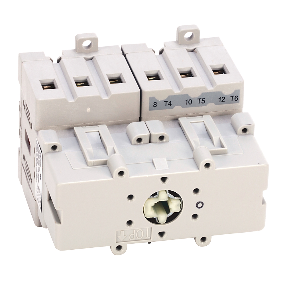
25 A 194E Load switch
| Unique Product Identifier |
194E-E25-1753-6N
|
|---|---|
| UPC |
662468863254
|
| Estimated Lead Time |
5 days
|
| Standard Warranty Duration |
1 year See details |
| Country of Origin |
Poland
|
The information provided by Rockwell Automation on www.rockwellautomation.com (the “Site”) is for demonstration purposes only and may be incomplete or inaccurate. All information is provided “as is”, and Rockwell Automation makes no representations or warranties of any kind, express or implied, regarding the accuracy, adequacy, validity, reliability, or completeness of any information on the Site. Use of this information is at your own risk.
| Interlockable |
True
|
|---|---|
| Version as emergency stop installation |
False
|
| Suitable for front mounting 4-hole |
True
|
| Suitable for front mounting centre |
True
|
| Colour control element |
Red
|
| Degree of protection (NEMA) |
Other
|
| Device construction |
Built-in device fixed built-in technique
|
| Tightening torque |
1.4 Nm (12.2 in-lb)
|
| Switch configuration |
OFF-ON 90°
|
| Rigid wire gauge |
1.5...16 mm2 (14...8 AWG)
|
| Fine strands wire gauge |
1.5...10 mm2 (14...8 AWG)
|
| Switch body height, approx |
64 mm (2-33/64 in) @ 25 A
|
| Switch body depth, approx |
60 mm (2-3/8 in) @ 25 A
|
| Switch body width, approx |
45 mm (1-25/32 in) @ 25 A
|
| Knockouts |
PG-type cable gland entry
|
| Wire gauge, max |
Terminal size per IEC 947-1: A6
|
| Protection class according to IEC 529 |
Switch bodies: IP20 @ motor rating 60 Hz
|
| Actuator type |
Supplied with a type N red/yellow actuator
|
| Installation |
Open-front/door
|
| Suitable for distribution board installation |
False
|
| Version as reversing switch |
False
|
| Version as main switch |
True
|
| Version as maintenance-/service switch |
True
|
| Degree of protection (IP), front side |
IP20
|
| Mechanical life operations |
200000
|
| Ambient enclosed temperature |
-20 °C
|
|---|---|
| Ambient storage temperature |
-40 °C
|
| Ambient operation temperature |
-25 °C
|
| Number of auxiliary contacts as normally open contact |
0
|
|---|---|
| Number of auxiliary contacts as normally closed contact |
0
|
| Conditioned rated short-circuit current Iq |
20 kA
|
| Rated permanent current Iu |
25 A
|
| Rated operation power at AC-23, 400 V |
11 kw
|
| Max. rated operation voltage Ue AC |
690 V
|
| Rated operation power at AC-3, 400 V |
7.5 kw
|
| Rated short-time withstand current lcw |
900 kA
|
| Type of control element |
Long turning handle
|
| Rated frequency |
60 Hz
|
| Switch size |
25 A
|
| Lost power per pole |
1 W
|
| Conventional free air thermal current (Ith) |
40 A per IEC
|
| Conventional enclosed thermal current (Ie) |
32 A per IEC
|
| Rated operational voltage (Ue) |
690V per IEC
|
| Rated isolation voltage (Ui) |
690V per IEC
|
| Continuous current |
UL/CSA (applications): 25 A
|
| Rated breaking capacity |
AC-23A (cosφ 0.45): 296A @ 230V
|
| Motor FLA rating |
UL/CSA application: 8.5A @ 480V, 60 Hz, 1 pole, 1 phase
|
| Hp motor rating |
UL/CSA application: 5Hp @ 600V, 60 Hz, 1 pole, 1 phase
|
| Fuse rating of circuit (type g, G), max |
Short circuit current (co-ordination type 2): 25A @ 400/415V
|
| Rated current (Ie) |
DC-21A (for resistive loads): 5A @ 220V, 2 pole in series, T ≤1 ms, Ue max = 660V
|
| Rated power (Pe) |
AC-3: 7.5 kW @ 690V
|
| Number of switches |
1
|
| Motor drive integrated |
False
|
| Voltage release optional |
False
|
| Type of electrical connection of main circuit |
Screw connection
|
| Switching rate |
120 ops/h
|
| Rated impulse voltage (Uimp) |
8 kV per UL, CSA
|
| Test voltage (Ui) |
2.5kV @ 1min
|
| Heavy pilot duty |
UL/CSA (applications): A600, AC
|
| General | Publication |
|---|---|
| Product Cutsheet | -- |
| Installation Instructions | Publication |
|---|---|
| 194e-in010_-en-p | 194E-IN010 |
| Technical Data | Publication |
|---|---|
| 194-td002_-en-p | 194-TD002 |
This product was certified with the above certifications as of 2026-05-19. Products sold before or after this date might carry different certifications. Please review the product label to check for the certifications your specific product carries.
Looking for certification documents?
Explore certifications for this product and more in our comprehensive Literature Library.
| EU Importer Address |
Rockwell Automation N.V |
|---|---|
| EU Authorized Representative Address |
Rockwell Automation N.V |
| Technotes |
|---|
Overview
| Unique Product Identifier |
194E-E25-1753-6N
|
|---|---|
| UPC |
662468863254
|
| Estimated Lead Time |
5 days
|
| Standard Warranty Duration |
1 year See details |
| Country of Origin |
Poland
|
The information provided by Rockwell Automation on www.rockwellautomation.com (the “Site”) is for demonstration purposes only and may be incomplete or inaccurate. All information is provided “as is”, and Rockwell Automation makes no representations or warranties of any kind, express or implied, regarding the accuracy, adequacy, validity, reliability, or completeness of any information on the Site. Use of this information is at your own risk.
Physical Characteristics
| Interlockable |
True
|
|---|---|
| Version as emergency stop installation |
False
|
| Suitable for front mounting 4-hole |
True
|
| Suitable for front mounting centre |
True
|
| Colour control element |
Red
|
| Degree of protection (NEMA) |
Other
|
| Device construction |
Built-in device fixed built-in technique
|
| Tightening torque |
1.4 Nm (12.2 in-lb)
|
| Switch configuration |
OFF-ON 90°
|
| Rigid wire gauge |
1.5...16 mm2 (14...8 AWG)
|
| Fine strands wire gauge |
1.5...10 mm2 (14...8 AWG)
|
| Switch body height, approx |
64 mm (2-33/64 in) @ 25 A
|
| Switch body depth, approx |
60 mm (2-3/8 in) @ 25 A
|
| Switch body width, approx |
45 mm (1-25/32 in) @ 25 A
|
| Knockouts |
PG-type cable gland entry
|
| Wire gauge, max |
Terminal size per IEC 947-1: A6
|
| Protection class according to IEC 529 |
Switch bodies: IP20 @ motor rating 60 Hz
|
| Actuator type |
Supplied with a type N red/yellow actuator
|
| Installation |
Open-front/door
|
| Suitable for distribution board installation |
False
|
| Version as reversing switch |
False
|
| Version as main switch |
True
|
| Version as maintenance-/service switch |
True
|
| Degree of protection (IP), front side |
IP20
|
| Mechanical life operations |
200000
|
Compliance & Environment
| Ambient enclosed temperature |
-20 °C
|
|---|---|
| Ambient storage temperature |
-40 °C
|
| Ambient operation temperature |
-25 °C
|
Electrical & Connectivity
| Number of auxiliary contacts as normally open contact |
0
|
|---|---|
| Number of auxiliary contacts as normally closed contact |
0
|
| Conditioned rated short-circuit current Iq |
20 kA
|
| Rated permanent current Iu |
25 A
|
| Rated operation power at AC-23, 400 V |
11 kw
|
| Max. rated operation voltage Ue AC |
690 V
|
| Rated operation power at AC-3, 400 V |
7.5 kw
|
| Rated short-time withstand current lcw |
900 kA
|
| Type of control element |
Long turning handle
|
| Rated frequency |
60 Hz
|
| Switch size |
25 A
|
| Lost power per pole |
1 W
|
| Conventional free air thermal current (Ith) |
40 A per IEC
|
| Conventional enclosed thermal current (Ie) |
32 A per IEC
|
| Rated operational voltage (Ue) |
690V per IEC
|
| Rated isolation voltage (Ui) |
690V per IEC
|
| Continuous current |
UL/CSA (applications): 25 A
|
| Rated breaking capacity |
AC-23A (cosφ 0.45): 296A @ 230V
|
| Motor FLA rating |
UL/CSA application: 8.5A @ 480V, 60 Hz, 1 pole, 1 phase
|
| Hp motor rating |
UL/CSA application: 5Hp @ 600V, 60 Hz, 1 pole, 1 phase
|
| Fuse rating of circuit (type g, G), max |
Short circuit current (co-ordination type 2): 25A @ 400/415V
|
| Rated current (Ie) |
DC-21A (for resistive loads): 5A @ 220V, 2 pole in series, T ≤1 ms, Ue max = 660V
|
| Rated power (Pe) |
AC-3: 7.5 kW @ 690V
|
| Number of switches |
1
|
| Motor drive integrated |
False
|
| Voltage release optional |
False
|
| Type of electrical connection of main circuit |
Screw connection
|
| Switching rate |
120 ops/h
|
| Rated impulse voltage (Uimp) |
8 kV per UL, CSA
|
| Test voltage (Ui) |
2.5kV @ 1min
|
| Heavy pilot duty |
UL/CSA (applications): A600, AC
|
Drawings
Documents
|
Product Cutsheet
General
-- |
|
194e-in010_-en-p
Installation Instructions
194E-IN010 |
|
194-td002_-en-p
Technical Data
194-TD002 |
| General | Publication |
|---|---|
| Product Cutsheet | -- |
| Installation Instructions | Publication |
| 194e-in010_-en-p | 194E-IN010 |
| Technical Data | Publication |
| 194-td002_-en-p | 194-TD002 |
Certifications
This product was certified with the above certifications as of 2026-05-19. Products sold before or after this date might carry different certifications. Please review the product label to check for the certifications your specific product carries.
Looking for certification documents?
Explore certifications for this product and more in our comprehensive Literature Library.
| EU Importer Address |
Rockwell Automation N.V |
|---|---|
| EU Authorized Representative Address |
Rockwell Automation N.V |
Accessories
Alternative Products
Technotes
| Technotes |
|---|