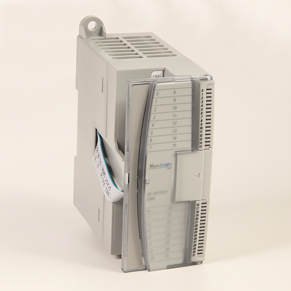
Loading
Allen-Bradley 1762-OB8 product image
Allen Bradley
1762-OB8

MicroLogix 8 Point Digital Output Module

PrintPrint
Print
EmailEmail
Share
Product RegistrationProduct Registration
QR code
Allen-Bradley 1762-OB8 product image
Allen Bradley
Lifecycle status: Active Mature
Product at a glance
Replacement Available
Lifecycle status: Active Mature
Product at a glance
Replacement Available
Add to BoM
  • Get Support
Technical Specifications
Drawings
Documents
Certifications
Technotes
Class
Progmable Logic Controller Module
Depth
87
digital output modules
8 Point 24V DC Source Output Module
Height
90
I/O Isolation
Isolated
I/O Status Indication
LED
Module Interfaces
Digital
Number Of Channels
8 Point
Output
8 Point, 24V DC Source
Temperature Rating
0…55 °C (32…131 °F)
Number of digital outputs
8
Suitable for safety functions
False
Digital inputs configurable
False
Digital outputs configurable
False
Type of output voltage
DC
Type of digital output
Relay
Type of electric connection
Screw connection
Heat dissipation, max
1.61 W
Continuous current per common, max
8A @ 30°C (86 °F)
Continuous current per module, max
8A @ 30°C (86 °F)
Continuous current per point, max
1A @ 30°C (86 °F)
Bus current draw, max
115mA @ 5V DC (0.575 W)
Signal delay, resistive load
On delay: 0.1 ms Off delay: 1.0ms
Power supply distance rating
6 (The module may not be more than 6 modules away from the power supply.)
Isolated groups
Group 1: Outputs 0...7
Surge current, max
2.0 A (Repeatability is once every 2 s at 55 °C (131 °F), once every s at 30 °C (86 °F) for a duration of 10 ms.)
Output group to backplane isolation
Verified by one of the following dielectric tests: 1200V AC @ 1s or 1697V DC @ 1s 75V DC working voltage (IEC Class 2 reinforced insulation)
Redundancy
False
Short-circuit protection, outputs available
False
Width
40.4 mm
Height
90 mm
Depth
87 mm
Weight
210 g
Shock
Operating: 30G panel mounted, 3 pulses per axis Relay ops: 7G
Vibration
Operating: 10…500 Hz, 5G, 0.030 in. max. peak-to-peak, 2 hr per axis Relay ops: 1.5G
On-state voltage drop, max
1.0V DC
Off-state leakage current, max
1 mA
Voltage category
24V DC
On-state current, min
1 mA
Operating voltage
20.4...26.4V DC
ESD immunity
IEC1000-4-2: 4kV contact, 8kV air, 4kV indirect
Conducted RF immunity
IEC 1000-4-6: 10V @ 0.15...80MHz
EFT/B immunity
IEC1000-4-4: 2kV @ 5kHz
Hazardous environment class
Hazardous Location, Class I, Division 2 Groups A, B, C, D (UL 1604, C-UL under CSA C22.2 No. 213)
Operating temperature
-20 to 65 °C
Surge transient immunity
IEC1000-4-5: 2 kV common mode, 1 kV differential mode
Radiated RF immunity
IEC1000-4-3: 10 V/m, 80...1,000 MHz, 80% Alitude modulation, +900 MHz keyed carrier
Altitude
2000 m
Storage temperature, min
-40 °C
Radiated and conducted emissions
EN50081-2: Class A
Operating humidity
5...95% noncondensing
Drawings
3-Dimensional STEP model (STP) Download (ZIP)
Product Drawing Drawing (DWG)
Drawings
3-Dimensional STEP model (STP) Download (ZIP)
Product Drawing Drawing (DWG)
Sign in to your Rockwell Automation account to view and download technical drawings.
Sign In
Type Resource Publication
General Product Cutsheet --
General Selection Guide 1761-SG001
Looking for more documentation?
Find curated technical documentation for this product in the Technical Documentation Center, or search our full Literature Library.
Search the Literature Library
  • UL Listed Hazardous

This product was certified with the above certifications as of 2025-07-20. Products sold before or after this date might carry different certifications. Please review the product label to check for the certifications your specific product carries.

Looking for more Technotes?
Find questions and answers from Rockwell Automation technical experts for this product in our Knowledgebase.
Search Knowledgebase
Technical Specifications
Class
Progmable Logic Controller Module
Depth
87
digital output modules
8 Point 24V DC Source Output Module
Height
90
I/O Isolation
Isolated
I/O Status Indication
LED
Module Interfaces
Digital
Number Of Channels
8 Point
Output
8 Point, 24V DC Source
Temperature Rating
0…55 °C (32…131 °F)
Number of digital outputs
8
Suitable for safety functions
False
Digital inputs configurable
False
Digital outputs configurable
False
Type of output voltage
DC
Type of digital output
Relay
Type of electric connection
Screw connection
Heat dissipation, max
1.61 W
Continuous current per common, max
8A @ 30°C (86 °F)
Continuous current per module, max
8A @ 30°C (86 °F)
Continuous current per point, max
1A @ 30°C (86 °F)
Bus current draw, max
115mA @ 5V DC (0.575 W)
Signal delay, resistive load
On delay: 0.1 ms Off delay: 1.0ms
Power supply distance rating
6 (The module may not be more than 6 modules away from the power supply.)
Isolated groups
Group 1: Outputs 0...7
Surge current, max
2.0 A (Repeatability is once every 2 s at 55 °C (131 °F), once every s at 30 °C (86 °F) for a duration of 10 ms.)
Output group to backplane isolation
Verified by one of the following dielectric tests: 1200V AC @ 1s or 1697V DC @ 1s 75V DC working voltage (IEC Class 2 reinforced insulation)
Redundancy
False
Short-circuit protection, outputs available
False
Width
40.4 mm
Height
90 mm
Depth
87 mm
Weight
210 g
Shock
Operating: 30G panel mounted, 3 pulses per axis Relay ops: 7G
Vibration
Operating: 10…500 Hz, 5G, 0.030 in. max. peak-to-peak, 2 hr per axis Relay ops: 1.5G
On-state voltage drop, max
1.0V DC
Off-state leakage current, max
1 mA
Voltage category
24V DC
On-state current, min
1 mA
Operating voltage
20.4...26.4V DC
ESD immunity
IEC1000-4-2: 4kV contact, 8kV air, 4kV indirect
Conducted RF immunity
IEC 1000-4-6: 10V @ 0.15...80MHz
EFT/B immunity
IEC1000-4-4: 2kV @ 5kHz
Hazardous environment class
Hazardous Location, Class I, Division 2 Groups A, B, C, D (UL 1604, C-UL under CSA C22.2 No. 213)
Operating temperature
-20 to 65 °C
Surge transient immunity
IEC1000-4-5: 2 kV common mode, 1 kV differential mode
Radiated RF immunity
IEC1000-4-3: 10 V/m, 80...1,000 MHz, 80% Alitude modulation, +900 MHz keyed carrier
Altitude
2000 m
Storage temperature, min
-40 °C
Radiated and conducted emissions
EN50081-2: Class A
Operating humidity
5...95% noncondensing
Drawings
Drawings
3-Dimensional STEP model (STP) Download (ZIP)
Product Drawing Drawing (DWG)
Drawings
3-Dimensional STEP model (STP) Download (ZIP)
Product Drawing Drawing (DWG)
Sign in to your Rockwell Automation account to view and download technical drawings.
Sign In
Documents
Product Cutsheet General
--
Selection Guide General
1761-SG001
Type Resource Publication
General Product Cutsheet --
General Selection Guide 1761-SG001
Looking for more documentation?
Find curated technical documentation for this product in the Technical Documentation Center, or search our full Literature Library.
Search the Literature Library
Certifications
  • UL Listed Hazardous

This product was certified with the above certifications as of 2025-07-20. Products sold before or after this date might carry different certifications. Please review the product label to check for the certifications your specific product carries.

Technotes
Looking for more Technotes?
Find questions and answers from Rockwell Automation technical experts for this product in our Knowledgebase.
Search Knowledgebase
Loading
Find your nearest distributor
Change location
EmailEmail
PhonePhone
Find a partner
MicroLogix 8 Point Digital Output Module
CloseClose
1762-OB8
Close
Print
Allen-Bradley 1762-OB8 product image
Phone:
Call
Rockwell Automation Home
Copyright ©2025 Rockwell Automation, Inc.
Sign in to your Rockwell Automation account to submit a repair documentation request.
Sign In
Request repair documentation
All fields with * are required for processing your request.
This field is required
Documentation of liability insurance is required for anyone who is requesting documentation for product repairs.
UploadUpload
Please upload documentation of liability insurance.*
1 file selected
CloseClose
File size is too large. Must be less than 5 MB.
Accepted file types: zip, pdf; Maximum size: 5 MB.
Right to Repair Terms and Conditions
Rockwell Automation is making, parts, and service documentation available at your request in compliance with applicable right to repair laws and regulations. By signing below, you are agreeing to the following terms and conditions of your purchase of Rockwell Automation genuine repair parts for repair of a Rockwell Automation product. As used below, “Self Service Repair Parts” means genuine Rockwell Automation parts (components of Rockwell Automation products) purchased from Rockwell Automation for installation in a Rockwell Automation product as part of a Self Service Repair. Self Service Repair Parts may be new or previously used genuine Rockwell Automation parts that have been tested and passed Rockwell Automation functional requirements. “Self Service Repair Tools” means equipment and related materials purchased for the purpose of performing repairs.
Your request has been successfully submitted.
Please allow up to 5 business days to receive a response to your inquiry.
  1. Chevron LeftChevron Left Rockwell Automation Home
  2. Chevron LeftChevron Left Products
Please update your cookie preferences to continue.
This feature requires cookies to enhance your experience. Please update your preferences to allow for these cookies:
  • Social Media Cookies
  • Functional Cookies
  • Performance Cookies
  • Marketing Cookies
  • All Cookies
You can update your preferences at any time. For more information please see our {0} Privacy Policy
CloseClose