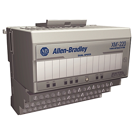
Speed Measurement Module
Speed Measurement Module
| Unique Product Identifier |
1440-SPD02-01RB
|
|---|---|
| UPC |
781180505355
|
| Estimated Lead Time |
129 days
|
| Standard Warranty Duration |
1 year See details |
| Country of Origin |
United States of America
|
| Nonvolatile configuration |
A copy of the module configuration is retained in nonvolatile memory from which the configuration is loaded upon powerup, The configuration that is stored in nonvolatile memory can be deleted only by a module-reset,command that is sent via a serial interf
|
|---|---|
| Output |
2
|
| Status indicator |
Module - red/green, Network - red/green, Channel 1 - yellow/red, Channel 2 - yellow/red, Startup - yellow, Relay - red, AUX - reserved for future use
|
| Tachometer Inputs |
2
|
| Consumption |
300 mA, max, 225 mA, typical
|
|---|---|
| Heat production |
7 W (24 BTU/hr), max, 4 W (14 BTU/hr), typical
|
| Isolation voltage |
250V (continuous), Basic Insulation Type, relay to all other circuits, Isolation between other circuits is not rated, Type tested at 1500V AC @ 60s
|
| Module |
24V DC
|
| Power dissipation, max |
7 W
|
| Rated control supply voltage at DC |
24 V
|
| Rated operating frequency |
0.0167 khz
|
| Transducer |
Isolated 24V DC, user configurable with wiring
|
| Type of electric connection |
Screw connection
|
| Voltage and current ratings |
Supply: 24V DC @ 0.3A max, Class 2/SELV, Relay: 120V AC @ 0.5A, 110V DC @ 0.5A, 30V DC @ 1.0A
|
| Voltage type for actuating |
DC
|
| Wire type |
Signal connections: shielded, Power and relay connections: unshielded
|
| Wiring category |
2 - on relay and signal ports, 3 - on serial and power ports, 2 - on XM bus ports
|
| Activation on |
Alarm Status: Normal, Alert, Danger, Disarm, Transducer fault, Module fault, Tacho fault
|
|---|---|
| Failsafe |
Normally energized (fail-safe), Normally de-energized (non-failsafe)
|
| Latching |
Latching, non-latching
|
| Logic |
Single or paired AND or OR logic that is applied to any alarm
|
| Number |
Single on-board relay, two sets of contacts - DPDT (two Form C), Four additional relays when interconnected to an XM-441 expansion relay module, or, Four virtual relays whose status can be used by remote control systems or the XM-440 master relay module
|
| On-board relay rating |
Voltage, max: 120V DC @ 125V AC, Current: 0…3.5 A, Power, max: 60 W, 62.5VA, max currentis up to 40 °C (104 °F), then derates to 2A @ 65°C (149 °F), Agency rating, 120V AC @ 0.5A, 110V DC @ 0.3A, 30V DC @ 1.0A
|
| Reset |
Local reset switch on top of module, Remote reset switch that is wired to terminal base, Digital reset command via serial or DeviceNet interface
|
| Time delay |
0…25.5 s, adjustable in 100 ms increments
|
| Input impedance |
120 kΩ minimum
|
|---|---|
| Speed measurement error |
1…240 rpm: ±0.2 rpm, 241…12,000 rpm: ±2 rpm, 12,001…20,400 rpm: ±5 rpm, 20,401…120,000 rpm: ±20 rpm, 120,001…360,000 rpm: ±50 rpm, 360,001…1,200,000 rpm: ±160 rpm
|
| Speed range |
1 r/m
|
| Two tachometer inputs |
±25V (50V max peak-to-peak), Eddy current transducer signals, Magnetic pickups, TTL output devices
|
| 4...20 mA outputs |
Each output is independently progmed to represent speed or acceleration, from either channel, Two isolated outputs, 300Ω max load, One active buffer per input channel
|
|---|---|
| Buffered outputs |
Output range configurable by wiring, -24...9V, -5…24V, -5…9V, Third buffered outpit available when the module is configured for single redundant channel mode, Outputs a CMOS (0…5V) level square-wave that corresponds to the active input signal
|
| DeviceNet network |
Standard DeviceNet protocol for all functions (not power-module power is provided independently), Available EDS file supports most DeviceNet compliant systems, Communication rate that is set automatically by bus master to 125 Kbps, 250 Kbps, or 500 Kbps,
|
|---|---|
| Serial |
RS-232 via mini-connector or terminal base unit, Communication rate that is fixed at 19.2 Kbps, Local configuration via the Serial Configuration Utility
|
| Alarm parameters |
Alarm and danger pair that is provided for each of: Speed, Acceleration, Zero speed, Locked rotor
|
|---|---|
| Hysteresis |
User configurable in software
|
| Operator |
Greater than, Less than, Inside range, Outside range
|
| Eddy current transducer |
Bias voltage is compared with the fault limits
|
|---|---|
| Magnetic pickups |
A current source is available for biasing passive magnetic pickups to detect open or short circuits
|
| Dual channel |
Two sensors are used independently to perform two separate speed, acceleration and peak speed measurements
|
|---|---|
| Reverse rotation |
Two sensors are used to monitor both speed and direction. The two sensors must be mounted out of phase from each other so that the rotational direction can be determined by monitoring which sensor the shaft keyway passes first
|
| Single redundant channel |
One sensor is used to perform the speed, acceleration, and peak speed measurements. If the current sensor fails, the module automatically switches to the s (redundant) sensor
|
| Measured parameters |
Forward, Reverse, Rpm, Direction of rotation, Acceleration in Rpm/min
|
|---|---|
| Peak speed capture |
The module retains the value of the highest speed that is observed since module power was cycled or the peak speed value was manually reset
|
| Units |
Rpm, Direction of rotation, Acceleration in rpm/min
|
| Conducted RF immunity |
10V rms with 1 kHz sine-wave 80% AM from 150 kHz...80 MHz
|
|---|---|
| Conformal coating |
All printed circuit boards are conformally coated in accordance with IPC-A-610C
|
| EFT/B immunity |
±2kV @ 5kHz on power ports, ±1kV @ 5kHz on relay and signal ports, ±1kV @ 5kHz on XM bus port
|
| ESD immunity |
6 kV contact discharges, 8 kV air discharges
|
| Emissions |
Class A
|
| Nonoperating temperature |
-40 °C
|
| Operating temperature |
-20 °C
|
| Radiated RF immunity |
10 V/m with 1 kHz sine-wave 80% AM from 80...2000 MHz, 10 V/m with 200 Hz 50% Pulse 100% AM @ 900 MHz, 10 V/m with 200 Hz 50% Pulse 100% AM @ 1890 MHz, 3 V/m with 1 kHz sine-wave 80% AM from 2000...2700 MHz
|
| Relative humidity |
5...95% noncondensing
|
| Storage temperature |
-40 °C
|
| Surge transient immunity |
±2 kV line-earth(CM) on relay and shielded signal ports, ±2 kV line-earth(CM) on XM bus port
|
| Surrounding air temperature, max |
65 °C
|
| Depth |
94 mm
|
|---|---|
| Function rotational speed monitoring |
True
|
| Height |
97 mm
|
| Shock |
Opsal: 15 G
|
| Vibration |
2.0 G @ 10…500 Hz
|
| Width |
94 mm
|
| Enclosure type rating |
None (open-style)
|
|---|
| General | Publication |
|---|---|
| Product Cutsheet | -- |
| Technical Data | Publication |
|---|---|
| 1440-td001_-en-p | 1440-TD001 |
| Accessory Files | Size | Notes | |
|---|---|---|---|
|
|
XM Serial Configuration Utility R8 | 12.04 MB | |
| EDS - Electronic Data Sheet Files | Size | Notes | |
|
|
EDS files for 1440-SPD02-01RB (multi) | 20.25 KB | |
|
|
EDS files for XM Family (multi) | 583 KB | |
| Firmware | Size | Notes | |
|
|
Firmware for 1440-SPD02-01RB v8.018 | 9.61 MB | |


This product was certified with the above certifications as of 2026-08-11. Products sold before or after this date might carry different certifications. Please review the product label to check for the certifications your specific product carries.
Looking for certification documents?
Explore certifications for this product and more in our comprehensive Literature Library.
| EU Importer Address |
Rockwell Automation N.V |
|---|---|
| EU Authorized Representative Address |
Rockwell Automation N.V |
| Technotes |
|---|
Overview
| Unique Product Identifier |
1440-SPD02-01RB
|
|---|---|
| UPC |
781180505355
|
| Estimated Lead Time |
129 days
|
| Standard Warranty Duration |
1 year See details |
| Country of Origin |
United States of America
|
Electrical & Connectivity
| Nonvolatile configuration |
A copy of the module configuration is retained in nonvolatile memory from which the configuration is loaded upon powerup, The configuration that is stored in nonvolatile memory can be deleted only by a module-reset,command that is sent via a serial interf
|
|---|---|
| Output |
2
|
| Status indicator |
Module - red/green, Network - red/green, Channel 1 - yellow/red, Channel 2 - yellow/red, Startup - yellow, Relay - red, AUX - reserved for future use
|
| Tachometer Inputs |
2
|
| Consumption |
300 mA, max, 225 mA, typical
|
|---|---|
| Heat production |
7 W (24 BTU/hr), max, 4 W (14 BTU/hr), typical
|
| Isolation voltage |
250V (continuous), Basic Insulation Type, relay to all other circuits, Isolation between other circuits is not rated, Type tested at 1500V AC @ 60s
|
| Module |
24V DC
|
| Power dissipation, max |
7 W
|
| Rated control supply voltage at DC |
24 V
|
| Rated operating frequency |
0.0167 khz
|
| Transducer |
Isolated 24V DC, user configurable with wiring
|
| Type of electric connection |
Screw connection
|
| Voltage and current ratings |
Supply: 24V DC @ 0.3A max, Class 2/SELV, Relay: 120V AC @ 0.5A, 110V DC @ 0.5A, 30V DC @ 1.0A
|
| Voltage type for actuating |
DC
|
| Wire type |
Signal connections: shielded, Power and relay connections: unshielded
|
| Wiring category |
2 - on relay and signal ports, 3 - on serial and power ports, 2 - on XM bus ports
|
| Activation on |
Alarm Status: Normal, Alert, Danger, Disarm, Transducer fault, Module fault, Tacho fault
|
|---|---|
| Failsafe |
Normally energized (fail-safe), Normally de-energized (non-failsafe)
|
| Latching |
Latching, non-latching
|
| Logic |
Single or paired AND or OR logic that is applied to any alarm
|
| Number |
Single on-board relay, two sets of contacts - DPDT (two Form C), Four additional relays when interconnected to an XM-441 expansion relay module, or, Four virtual relays whose status can be used by remote control systems or the XM-440 master relay module
|
| On-board relay rating |
Voltage, max: 120V DC @ 125V AC, Current: 0…3.5 A, Power, max: 60 W, 62.5VA, max currentis up to 40 °C (104 °F), then derates to 2A @ 65°C (149 °F), Agency rating, 120V AC @ 0.5A, 110V DC @ 0.3A, 30V DC @ 1.0A
|
| Reset |
Local reset switch on top of module, Remote reset switch that is wired to terminal base, Digital reset command via serial or DeviceNet interface
|
| Time delay |
0…25.5 s, adjustable in 100 ms increments
|
| Input impedance |
120 kΩ minimum
|
|---|---|
| Speed measurement error |
1…240 rpm: ±0.2 rpm, 241…12,000 rpm: ±2 rpm, 12,001…20,400 rpm: ±5 rpm, 20,401…120,000 rpm: ±20 rpm, 120,001…360,000 rpm: ±50 rpm, 360,001…1,200,000 rpm: ±160 rpm
|
| Speed range |
1 r/m
|
| Two tachometer inputs |
±25V (50V max peak-to-peak), Eddy current transducer signals, Magnetic pickups, TTL output devices
|
| 4...20 mA outputs |
Each output is independently progmed to represent speed or acceleration, from either channel, Two isolated outputs, 300Ω max load, One active buffer per input channel
|
|---|---|
| Buffered outputs |
Output range configurable by wiring, -24...9V, -5…24V, -5…9V, Third buffered outpit available when the module is configured for single redundant channel mode, Outputs a CMOS (0…5V) level square-wave that corresponds to the active input signal
|
| DeviceNet network |
Standard DeviceNet protocol for all functions (not power-module power is provided independently), Available EDS file supports most DeviceNet compliant systems, Communication rate that is set automatically by bus master to 125 Kbps, 250 Kbps, or 500 Kbps,
|
|---|---|
| Serial |
RS-232 via mini-connector or terminal base unit, Communication rate that is fixed at 19.2 Kbps, Local configuration via the Serial Configuration Utility
|
Technical Specifications
| Alarm parameters |
Alarm and danger pair that is provided for each of: Speed, Acceleration, Zero speed, Locked rotor
|
|---|---|
| Hysteresis |
User configurable in software
|
| Operator |
Greater than, Less than, Inside range, Outside range
|
| Eddy current transducer |
Bias voltage is compared with the fault limits
|
|---|---|
| Magnetic pickups |
A current source is available for biasing passive magnetic pickups to detect open or short circuits
|
| Dual channel |
Two sensors are used independently to perform two separate speed, acceleration and peak speed measurements
|
|---|---|
| Reverse rotation |
Two sensors are used to monitor both speed and direction. The two sensors must be mounted out of phase from each other so that the rotational direction can be determined by monitoring which sensor the shaft keyway passes first
|
| Single redundant channel |
One sensor is used to perform the speed, acceleration, and peak speed measurements. If the current sensor fails, the module automatically switches to the s (redundant) sensor
|
| Measured parameters |
Forward, Reverse, Rpm, Direction of rotation, Acceleration in Rpm/min
|
|---|---|
| Peak speed capture |
The module retains the value of the highest speed that is observed since module power was cycled or the peak speed value was manually reset
|
| Units |
Rpm, Direction of rotation, Acceleration in rpm/min
|
Compliance & Environment
| Conducted RF immunity |
10V rms with 1 kHz sine-wave 80% AM from 150 kHz...80 MHz
|
|---|---|
| Conformal coating |
All printed circuit boards are conformally coated in accordance with IPC-A-610C
|
| EFT/B immunity |
±2kV @ 5kHz on power ports, ±1kV @ 5kHz on relay and signal ports, ±1kV @ 5kHz on XM bus port
|
| ESD immunity |
6 kV contact discharges, 8 kV air discharges
|
| Emissions |
Class A
|
| Nonoperating temperature |
-40 °C
|
| Operating temperature |
-20 °C
|
| Radiated RF immunity |
10 V/m with 1 kHz sine-wave 80% AM from 80...2000 MHz, 10 V/m with 200 Hz 50% Pulse 100% AM @ 900 MHz, 10 V/m with 200 Hz 50% Pulse 100% AM @ 1890 MHz, 3 V/m with 1 kHz sine-wave 80% AM from 2000...2700 MHz
|
| Relative humidity |
5...95% noncondensing
|
| Storage temperature |
-40 °C
|
| Surge transient immunity |
±2 kV line-earth(CM) on relay and shielded signal ports, ±2 kV line-earth(CM) on XM bus port
|
| Surrounding air temperature, max |
65 °C
|
Physical Characteristics
| Depth |
94 mm
|
|---|---|
| Function rotational speed monitoring |
True
|
| Height |
97 mm
|
| Shock |
Opsal: 15 G
|
| Vibration |
2.0 G @ 10…500 Hz
|
| Width |
94 mm
|
| Enclosure type rating |
None (open-style)
|
|---|
Documents
|
Product Cutsheet
General
-- |
|
1440-td001_-en-p
Technical Data
1440-TD001 |
| General | Publication |
|---|---|
| Product Cutsheet | -- |
| Technical Data | Publication |
| 1440-td001_-en-p | 1440-TD001 |
Downloads
| Accessory Files | Size | Notes | |
|---|---|---|---|
|
|
XM Serial Configuration Utility R8 | 12.04 MB | |
| EDS - Electronic Data Sheet Files | Size | Notes | |
|
|
EDS files for 1440-SPD02-01RB (multi) | 20.25 KB | |
|
|
EDS files for XM Family (multi) | 583 KB | |
| Firmware | Size | Notes | |
|
|
Firmware for 1440-SPD02-01RB v8.018 | 9.61 MB | |
Certifications
This product was certified with the above certifications as of 2026-08-11. Products sold before or after this date might carry different certifications. Please review the product label to check for the certifications your specific product carries.
Looking for certification documents?
Explore certifications for this product and more in our comprehensive Literature Library.
| EU Importer Address |
Rockwell Automation N.V |
|---|---|
| EU Authorized Representative Address |
Rockwell Automation N.V |
Alternative Products
Technotes
| Technotes |
|---|
