Threshold Templates
The threshold template displays the current voltage thresholds for the module. When adding or modifying a threshold template, apply the same value to all channels of a module or define individual values for each channel.
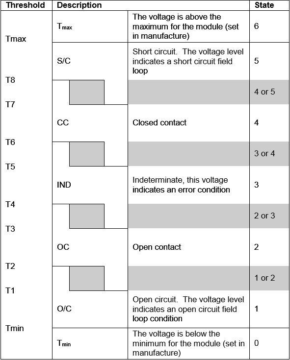
Input modules monitor and calculate the voltage level from the field at each channel to determine the appropriate state to report to the TMR Processor. After calculating the input channel voltage, a state is then determined based on the channel threshold settings. There are eight possible states (0 to 7). The following example displays state thresholds for a line monitored digital input switch configuration:
TIP:
States 0 to 6 are based on the calculated voltage.
State 7 is reported when the module completely fails.
There are fixed minimum (Tmin) and maximum (Tmax) thresholds for the module. Each channel has eight configurable thresholds. Each state transition has a hysteresis, as seen in gray in the example above.
Apply the following rules when configuring thresholds:
- Each threshold is greater than or equal to the previous threshold, for example, T2 is greater or equal to T1, T3³T2 etc…
- The state associated with each threshold is between the threshold settings, except that the lower threshold is higher than Tmin (in the valid OC state range), and the upper threshold is lower than Tmax (in the valid SC state range).
- Threshold values are defined as fractions of a volt. For example, in the 8403 Digital Input Module, thresholds are represented as 512 counts per volt; for example, a value of 8400 represents 16.406 volts (8400/512). The various Product Descriptions define the threshold fractions used for applicable modules.
When using the
Threshold Template Editor
, use the following syntax to define the same threshold values for all channels:default = <T1>, <T2>, <T3>, <T4>, <T5>, <T6>, <T7>, <T8>
Use the following syntax to define individual channel thresholds:
channel# = <default> | <T1>, <T2>, <T3>, <T4>, <T5>, <T6>, <T7>, <T8>
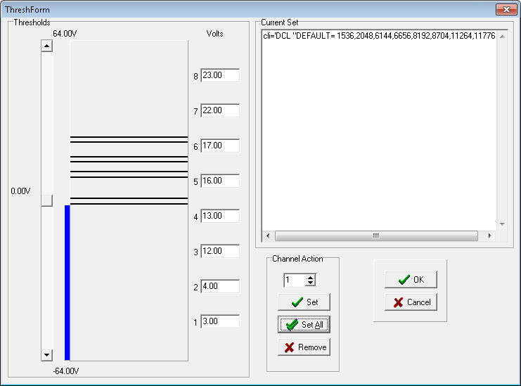
The bar graph displays the current voltage thresholds. Modify the values by either dragging the horizontal lines on the bar graph or by entering the voltage values. Use the scroll bar to display the threshold settings.
Task | Procedure |
|---|---|
Define the threshold values for all channels of a module | The displayed default threshold values are dependent on the module type.
|
Define the threshold value for a channel |
|
Remove the threshold values |
|
Provide Feedback