
Dual Channel Input Monitor (DCM)
Supported controllers and software
Supported controllers | Supported controller firmware versions |
|---|---|
Compact GuardLogix 5380 Safety | 37.00 and later |
GuardLogix 5580 Safety | 37.00 and later |
ControlLogix 5590 | 38.00 and later |
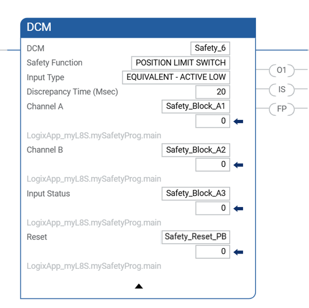
The Dual Channel Input Monitor instruction monitors dual-input safety devices and sets O1
(Output 1) based on the Input Type operand and the combined state of Channel A and Channel
B.
Available Languages
Ladder Diagram
Function Block
This instruction is not available in function block.
Structured Text
This instruction is not available in structured text.
Operands
IMPORTANT:
Unexpected operation, including controller
assert or a Major Non-Recoverable Fault, can occur if:
- Backing tag members are written to.
- Backing tags are shared by multiple instruction invocations.
- Backing tag members are passed as parameters to an instruction controlled by the same backing tag.
- The backing tag.EnableInmember is referenced anywhere in the program..EnableInis a parameter that represents rung state into an instruction and is only intended for internal use.For examples of these incorrect backing tag usages, see Backing tag usages that can cause unexpected operation.
IMPORTANT:
Make sure safety input points are configured as single, not Equivalent or Complementary.
These instructions provide all dual channel functionality necessary for PLd (Cat. 3) or Ple
(Cat. 4) safety functions.
ATTENTION:
If changing instruction operands while in Run mode, accept the pending edits and cycle the
controller mode from Program to Run for the changes to take effect.
The following table provides the operands that are used to configure the instruction. These
operands cannot be changed at runtime.
Operand | Data Type | Format | Description |
|---|---|---|---|
DCM | DCI_MONITOR | tag | DCM structure |
Safety Function | DINT | list item | This operand provides a text name for how this instruction is being used. Choices
include cam switch (40), position limit switch (41), and user-defined (100). This operand does not affect instruction behavior. It is for
information/documentation purposes only. |
Input Type | DINT | list item | This operand selects input channel behavior. Equivalent - Active High (0) : Inputs are in the active state when Channel A
and Channel B inputs are 1.Equivalent - Active Low (1) : Inputs are in the active state when Channel A
and Channel B inputs are 0.Complementary (2) : Inputs are in the active state when Channel A is 1 and
Channel B is 0. |
Discrepancy Time (ms) | DINT | immediate | The amount of time that the inputs can be in an inconsistent state before an
instruction fault is generated. The inconsistent state depends on the Input
Type. Equivalent: Inconsistent state is when either is true: Channel A = 0 and Channel B =1 Channel A =1 and Channel B =0 Complementary: Inconsistent state is when either is true: Channel A = 0 and Channel B =0 Channel A =1 and Channel B =1 If this operand is 0, the Discrepancy Time checking is disabled (0 = infinite). The
allowable range is 0...3000 ms. |
The following table explains instruction inputs. The inputs may be field device signals from
input devices or derived from user logic.
Operand | Data Type | Format | Description |
|---|---|---|---|
Channel A 1 | BOOL | tag | This input is one of the two inputs being monitored. When either input is in the
safe state, Output 1 is de-energized. |
Channel B 1 | BOOL | tag | This input is one of the two inputs being monitored. When either input is in the
safe state, Output 1 is de-energized. |
Input Status | BOOL | immediate tag | If instruction inputs are from a safety I/O module, this is the status from the I/O
module (Connection Status or Combined Status). If instruction inputs are derived
from internal logic, it is the application programmer’s responsibility to determine
the conditions. ON (1): The inputs to this instruction are valid. OFF (0): The inputs to this instruction are invalid. |
Reset 2 | BOOL | tag | This input clears the instruction faults provided the fault condition is not
present. OFF (0) -> ON (1): The Fault Present and Fault Code outputs are reset. |
1
If the input is from a Guard I/O
input module, make sure that
the input is configured as single, not Equivalent or Complementary. 2
Some safety standards require monitoring the transition of the reset
input. When the reset is used to reset a safety function, additional logic may be
required to verify a transition of the reset input from High-to-Low or
Low-to-High.The following table explains instruction outputs. The outputs may be external tags (safety
output modules) or internal tags for use in other logic routines.
Operand | Data Type | Description |
|---|---|---|
Output 1 (O1) | BOOL | This output is energized (1) when the input conditions are satisfied. The output becomes de-energized (0) when:
|
Instruction Status (IS) | BOOL | This output is ON (1) when Output 1 of this instruction is valid (no faults or
diagnostics are present). |
Fault Present (FP) | BOOL | ON (1): A fault is present in the instruction. OFF (0): This instruction is operating normally. |
Fault Code | DINT | This output indicates the type of fault that occurred. See the Fault Codes section
below for a list of fault codes. This operand is not safety-related. |
Diagnostic Code | DINT | This output indicates the diagnostic status of the instruction. See the Diagnostic
Codes for a list of diagnostic codes. This operand is not safety-related. |
IMPORTANT:
Do not write to any instruction output tag under any circumstances.
Affects Math Status Flags
No
Major/Minor Faults
None specific to this instruction. See Index Through Arrays for array-indexing faults.
Execution
Condition/State | Action Taken |
|---|---|
Prescan | Same as Rung-condition-in is false. |
Rung-condition-in is false | The .O1, .IS, and .FP are cleared to false. |
Rung-condition-in is true | The instruction executes as described in the operation section. |
Postscan | Same as Rung-condition-in is false. |
Operation
Normal Operation
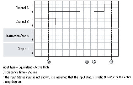
The timing diagram illustrates the normal monitoring of a dual-channel input with the Input
Type configured as Equivalent - Active High. Output 1 is ON (1) initially because the safety
inputs are in the active state. At (A), Channel A transitions to the safe state, which causes
Output 1 to go to the safe state. At (B), both of the safety inputs have transitioned to the
active state, which energizes Output 1. At (C), Output 1 is de-energized and energized again
at (D).
The Instruction Status is ON (1) the entire time because no faults or diagnostics occur.
Input Status Fault Operation
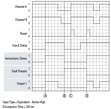
The timing diagram illustrates instruction behavior with fault conditions. At (A), Output 1
turns ON (1) when the Input Status becomes valid. This also energizes Output 1 because the
safety inputs are in the active state. At (B), a fault is generated when the Input status
becomes invalid. This also turns OFF (0) the Instruction Status output. At (C), the fault
cannot be reset because the Input Status is still invalid. At (D), the fault is cleared when a
reset is triggered with the Input Status being valid. This also turns the Instruction Status
output ON (1).
Discrepancy Fault Operation
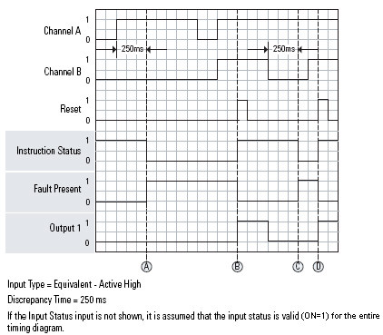
The timing diagram illustrates a discrepancy fault occurring when Channel A and Channel B are
in an inconsistent state for longer than the Discrepancy Time. At (A), a fault is generated
when the safety inputs are in an inconsistent state for longer than the Discrepancy Time. This
also turns Output 1 OFF (0). At (B), the fault is cleared because a Reset is triggered when
the safety inputs are no longer in an inconsistent state. At (C), the fault is generated when
the safety inputs are again in an inconsistent state for longer than the Discrepancy Time. At
(D), the fault is reset.
False Rung State Behavior
When the instruction is executed on a false rung, all instruction outputs are
de-energized.
Fault Codes and Corrective Actions
The fault codes are listed in hexadecimal format followed by decimal format.
Fault Code | Description | Corrective Action |
|---|---|---|
0 | No fault. | None. |
16#20 32 | The Input Status input transitioned from ON (1) to OFF (0) while the instruction
was executing. |
|
16#4000 16384 | Channel A and Channel B were in an inconsistent state for longer than the
Discrepancy Time. At the time of the fault, Channel A was in the active state.
Channel B was in the safe state. |
|
16#4001 16385 | Channel A and Channel B were in an inconsistent state for longer than the
Discrepancy Time. At the time of the fault, Channel A was in the safe state. Channel
B was in the active state. | |
16#4002 16386 | Channel A went to the safe state and back to the active state while Channel B
remained active. | |
16#4003 16387 | Channel B went to the safe state and back to the active state while Channel A
remained active. |
Diagnostic Codes and Corrective Actions
The diagnostic codes are listed in hexadecimal format followed by decimal format.
Diagnostic Code | Description | Corrective Action |
|---|---|---|
0 | No fault. | None. |
16#20 32 | The Input Status was OFF(0) when the instruction started. | Check the I/O module connection or the internal logic used to source input
status. |
Provide Feedback