INTEGRAL
The INTEGRAL instruction integrates a real value during the defined cycle time.
- When the INTEGRAL function block is first initialized, its initial values are not considered. Use the R1 parameter to set the initial values for a calculation.
- To prevent the loss of the integrated value, the integration value is not cleared automatically when the controller transitions fromProgramtoRunor when the Run parameter transitions from FALSE to TRUE. Use the R1 parameter to clear the integral value when first transitioning the controller fromProgramtoRunmode and when starting a new integration.
- We do not recommend using the optional EN or ENO parameters with this function block because the cycle time calculation becomes disrupted when EN is FALSE, resulting in an incorrect integration. If the EN or ENO parameters are used, toggle the R1 parameter with EN equal to TRUE to clear the current result and ensure correct integration.
- Integration is performed with a time base of milliseconds (that is, integrating an input of 1 with an initial value of 0 for 1 second results in a value of 1000). To convert the output of the instruction to units of seconds, divide the output by 1000.
- If the CYCLE parameter value is less than the cycle timing of the execution of the device, the sampling period is forced to the cycle timing.
- XIN sampling and function block executions occur every cycle time + Scan Time Jitter.
- For a given user program, Scan Time Jitter varies from controller to controller.
- The cycle time determines the sensitivity of the Integral function block. Changes occurring in XIN between two samplings (or within the cycle time) are not taken into account when the integral XOUT value is calculated.
- Cycle time and Scan Time Jitter both contribute to the overall inaccuracy of Integral output as shown in the XIN in sync with the function block execution example and the XIN not in sync with function block execution example.
Languages supported: Function block diagram, ladder diagram, structured text.
This instruction applies to the Micro810, L20E, L50E, and L70E controllers.
INTEGRAL
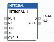
Parameter | Parameter Type | Data Type | Description |
|---|---|---|---|
RUN | Input | BOOL | Mode:
|
R1 | Input | BOOL | Overriding reset. |
XIN | Input | REAL | Input: Any real value. |
X0 | Input | REAL | Initial value. |
CYCLE | Input | TIME | Sampling period. Possible values range from 0ms through 49d17h2m47s294ms. |
Q | Output | BOOL | Not R1. |
XOUT | Output | REAL | Integrated output. |
INTEGRAL examples
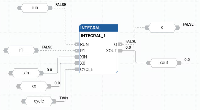
INTEGRAL function block diagram example
INTEGRAL ladder diagram example

INTEGRAL structured text example
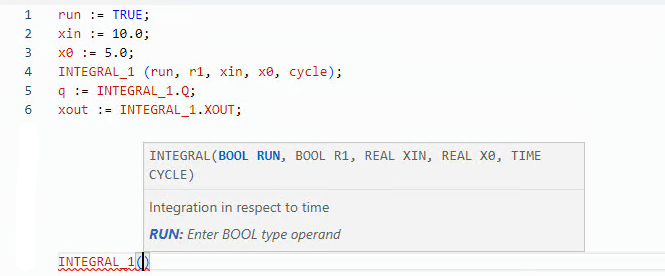
(* ST Equivalence: INTEGRAL1 is an instance of a INTEGRAL block *)

INTEGRAL1(manual_mode, NOT(manual_mode), sensor_value, init_value, t#100ms);

controlled_value := INTEGRAL1.XOUT;
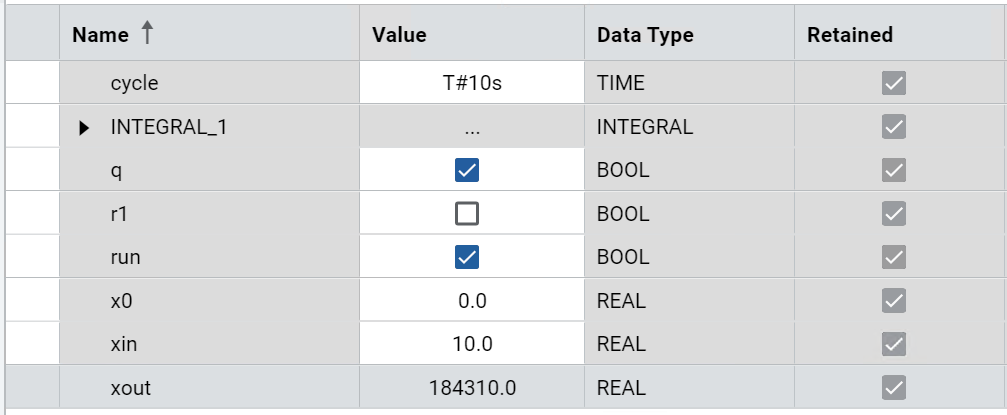
Results
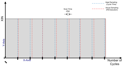
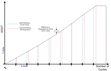
XIN in sync with function block execution example
The following images show the effect of Scan Time Jitter on the XOUT value:
Effect of Scan Time Jitter on the XOUT value
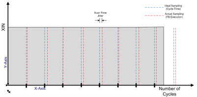
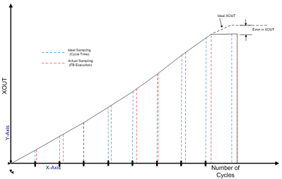
XIN not in sync with function block execution example
The following images show an example in which an error is introduced in the XOUT value of an Integral function block:
Example where an error is introduced in the XOUT value of an Integral function block
Provide Feedback