
Example of Using the 5034-ENC Module with a 24-bit SSI Sensor
The following figure illustrates the SSI clock (CLK) signal that is sent to the SSI
sensor by the 5034-ENC module and the SSI data (DATA) coming back to the module from the
sensor.
5034-ENC with 24-bit SSI Sensor Example
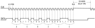
The CLK and DATA signals are representative of what you could actually see on an
oscilloscope when the module is attached to a SSI sensor in a live system. The SSI
module must be configured for a SSI Word length of 24, as well as the proper Data Rate
and SSI Word Delay time that are stated in the SSI sensor specifications.
SSI Word Delay time is approximately equal to a value called monoflop time, as stated by
some SSI sensor manufacturers. When configuring the 5034-ENC module, enter the monoflop
time value for SSI Word Delay time.
Point A of the CLK signal is a falling clock edge. When the SSI sensor sees the first
falling clock edge after a delay period, it knows to latch its current position into a
parallel-to-serial converter that is located in the sensor.
At point B of the CLK signal is the rising clock edge. The sensor begins to send its
serial data to the 5034-ENC module. The module actually starts reading the sensor
position data on the next rising clock edge, denoted by MSB in the figure above. MSB is
the most significant bit of the data word.
The 5034-ENC module supports only MSB aligned data. This means that the SSI sensor sends
the MSB of its data word first, and the least significant bit (LSB) is sent last.
Observe that it takes 25 rising clock edges to read a 24-bit data word from a 24-bit SSI
sensor. A 25-bit sensor needs 26 rising edges and a 13-bit sensor needs 14 edges.
Configure the module for the SSI Word Length as stated in the sensor specifications and
the module adds the extra rising edge automatically.
The actual bit values of the current SSI sensor position are shown beneath the Data
signal in the figure. A bit value is always the binary (0 or 1) value just before a
given rising clock edge. The next binary value is sent by the SSI sensor just after the
rising clock edge and is read by the module on the next rising clock edge.
Provide Feedback