
EtherNet/IP In-cabinet Devices
The
EtherNet/IP™
In-cabinet system consists of the following supported devices:- 1834-AENTREtherNet/IP™gateway
- 1834-SUP-PWR supplemental power tap
- 1486-CON-x flat media connectors to connect communication interfaces and devices to the system
- 1486-CBL flat media cable to connect all system components
- 800F, 100-E, and 104-E communication interface modules
The individual devices on the system bus appear as devices in the Controller Organizer of the
controller project and automatically generate I/O tags.
1834-AENTR Gateway
The 1834-AENTR gateway is the primary network power source. It connects the devices on the
EtherNet/IP™
In-cabinet bus to a standard EtherNet/IP™
network to allow communication between a Logix 5000®
controller and the devices.1834-AENTR Gateway
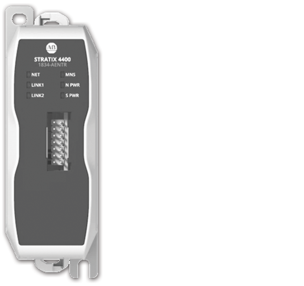
Features include:
- Dual RJ45 ports for Device Level Ring (DLR) connection, Dynamic Host Configuration Protocol (DHCP), or rotary switch to set the IP address
- One 1486-CBL flat media cable connection
- Auto-IP commissioning of connected devices
- Configuration using programming software
- Maximum of 40 node connections (includes the gateway as 1 connection)
- Maximum of 25 m (82 ft) flat media cable per gateway
1834-SUP-PWR Supplemental Power Tap
The 1834-SUP-PWR supplemental power tap uses external power to inject and regulate added
switched power to the bus. The supplemental power tap is essential if the switched power
that is provided by the integrated gateway becomes insufficient due to an increased number
of devices.
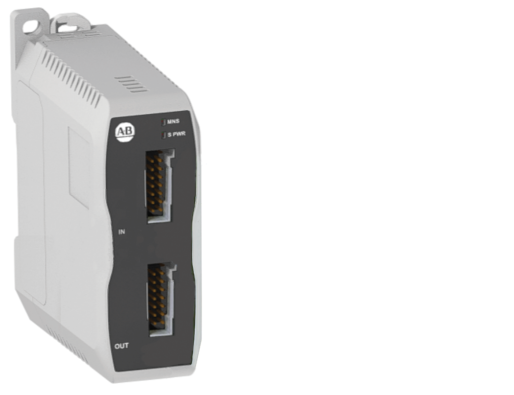
Features include:
- Injects 4 A of additional switch power with a surge boost in power, up to 8 A, into the in-cabinet network
- Zone control to disable coil control in the event of a safety or maintenance lockout
- Ideal for simultaneous motor starting with multiple, or large-rated devices (such as contactors)
- Allows network power pass-through
- Node count per module:
- 1 for network cable systems ≤ 12 m (39.4 ft)
- 2 for network cable systems between 13...25 m (42.7...82.0 ft)
100-E and 104-E Communication Interface Modules
100-E and 104-E communication interface modules connect the starters to the system.
Cat. No. | Description | Use |
|---|---|---|
100-E-INT-D 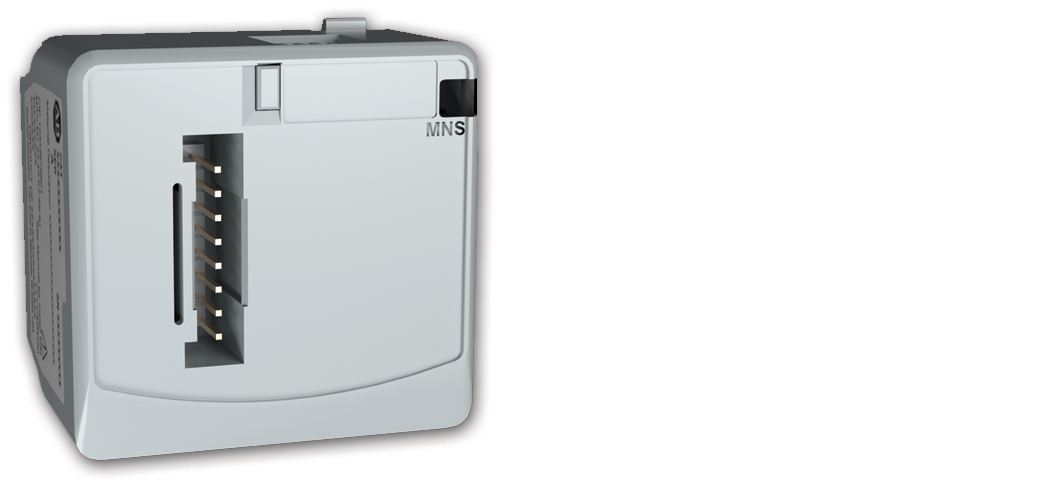 | Non-reversing starter plus discrete input for interlocking | 2-component or 3-component motor starter connecting the discrete input to a trip
contact/ condition from a connected overload relay or motor protection circuit
breaker (MPCB) |
104-E-INT-D 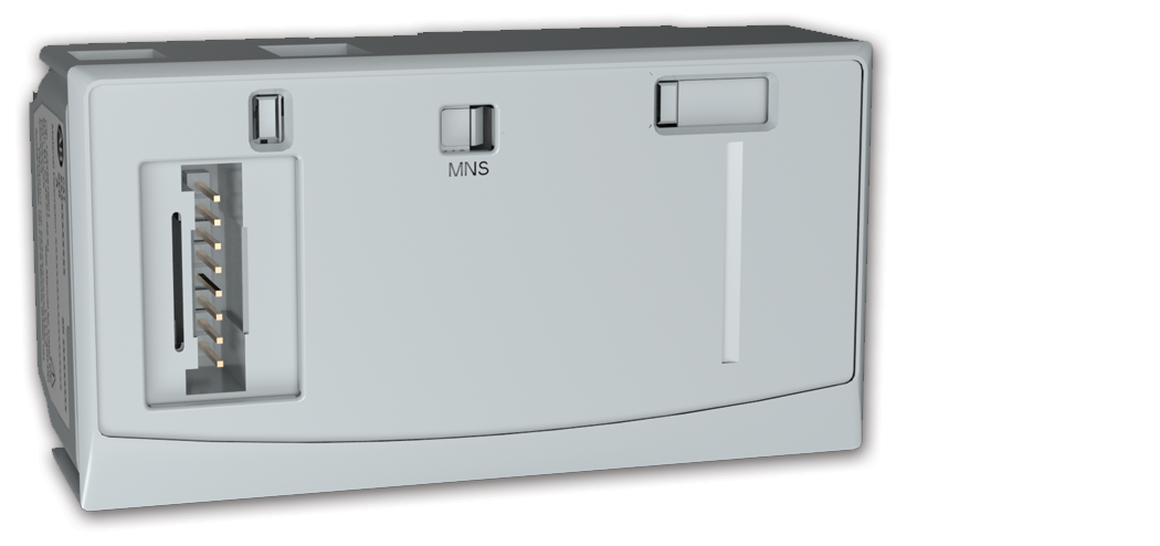 | Reversing starter plus discrete input for interlocking | 2-component or 3-component motor starter connecting the discrete input to a trip
contact/ condition from a connected overload relay or motor protection circuit
breaker (MPCB) |
100-E-INT-X 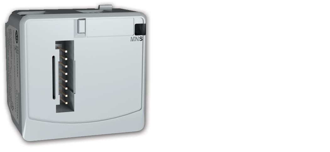 | Non-reversing starter with discrete input for interlocking plus data port
communications | 2-component or 3-component motor starter (similar to 100E-INT-D) with a data port
connection to a 140ME Motor Connection Circuit Breaker (MCCB), or a E100
solid-state motor overload relay |
104-E-INT-X | Reversing starter with discrete input for interlocking plus data port
communications | 2-component or 3-component motor starter (similar to 104-E-INT-D) with a data
port connection to a 140ME Motor Connection Circuit Breaker (MCCB), or a E100
solid-state motor overload relay |
800F Communication Interface Modules for 800F Operators
Cat. No. | Description | Use |
|---|---|---|
800F-INT 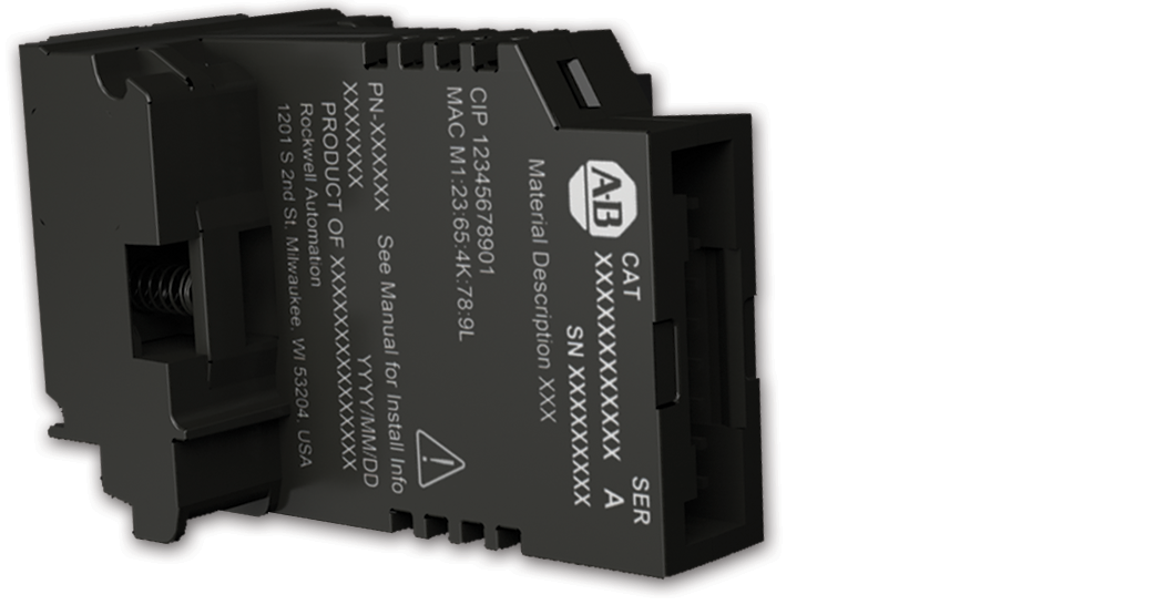 | Non-illuminated communication interface module | For non-illuminated 22 mm push buttons |
800F-INT-L 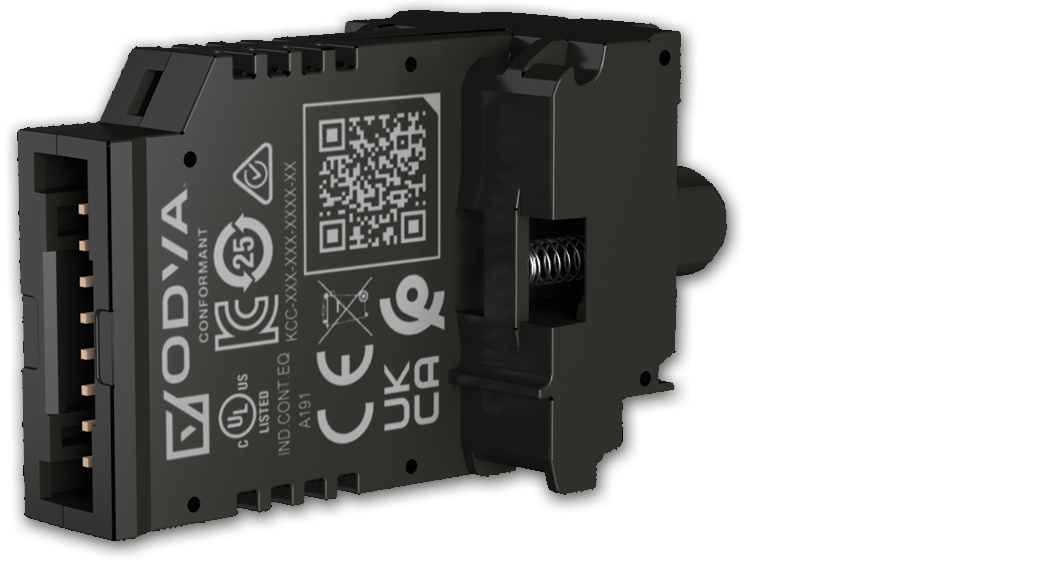 | Illuminated communication interface module | For illuminated 22 mm push buttons and pilot lights |
Provide Feedback