EtherNet/IP Integration Between CompactLogix and UR5 Cobot
Practical guide to connect a UR5 CB-Series to CompactLogix 5480 through EtherNet/IP, interpret robot data in Studio 5000, and send values from the PLC to PolyScope. - [Implementation Time: 60 Minutes]
This application integrates a Universal Robots UR5 cobot with an Allen-Bradley CompactLogix 5480 controller via EtherNet/IP. The CompactLogix operates as the connection originator/scanner and the UR5 as the target/adapter, enabling cyclic exchange of process data between both controllers.
The implementation shown in this guide was developed using a CompactLogix 5069-L4200ERMW connected through its LAN B1 interface, a Stratix 5700 switch, a UR5 CB-Series robot with PolyScope 3, and an engineering workstation running Studio 5000 Logix Designer. The guide validates both the reading of robot information by the PLC and the transmission of data from the PLC to the UR5.
What does this application do?
The objective is to provide a practical, reusable reference for integrating a UR5 into a machine or automated cell controlled by Logix. The connection allows the PLC to monitor robot status, joint positions, TCP information, I/O signals, and general-purpose registers, as well as transfer commands or parameters from the CompactLogix to a PolyScope program.
Downloads
Please note: You will need to agree to the Terms & Conditions for each download.
If you need help with an application or have feedback from the Innovation Center, please contact us.
Is this application relevant to me?
This application is useful when the CompactLogix must coordinate the overall process sequence and the robot must operate as a subsystem within the cell. Key benefits include:
Establishing standardized cyclic EtherNet/IP communication between CompactLogix and Universal Robots.
Reading robot status, operating modes, safety variables, joints, TCP, I/O, and general-purpose registers from the PLC.
Sending parameters, commands, and test values from Studio 5000 to a PolyScope program.
Creating a reusable foundation for Ready, Busy, Done, and Fault handshakes, as well as recipe or task selection.
Simplify diagnostics by making robot information available directly in Controller Tags.
The following hardware and software environment is required to run the application.
Controller Revision and Software Compatibility
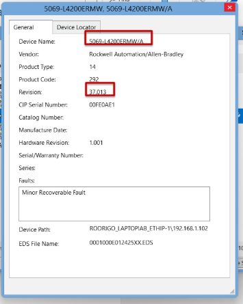
The CompactLogix 5480 controller requires Studio 5000 Logix Designer v32.01 or later. Additionally, firmware v32.012 is required as the base revision for the generation. For this exercise, the physical controller was identified as running revision 37.013; therefore, it is recommended to use Studio 5000 v37.x and create the project using the same major revision as the controller to avoid incompatibilities during the download process.
IMPORTANT: If the revision installed on the controller is not available in Studio 5000, install support for that revision or consider a firmware update. A flashing process must not be interrupted by a loss of power or communication, as this could render the controller inoperable.
SAFETY: Safety states received via EtherNet/IP are useful for diagnostics and supervisory logic; however, the standard EtherNet/IP connection described here does not replace the hardwired or safety-rated safety functions required by the cell's risk assessment.
The following steps document the complete configuration used to establish and validate bidirectional communication between the CompactLogix and the UR5. The images are presented in the order of execution, and each is sequentially numbered for easy reference during the exercise.
Create the Studio 5000 project and identify the controller.
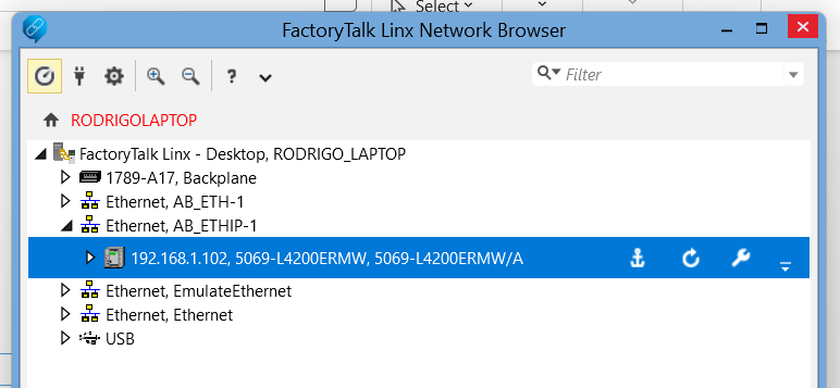
Open Studio 5000 Logix Designer and create a new project. Before selecting the revision, use FactoryTalk Linx Network Browser to locate the connected CompactLogix and verify its catalog number and firmware. This application uses a 5069-L4200ERMW with IP address 192.168.1.102 and revision 37.013.
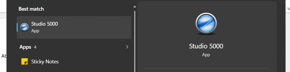
Open the Windows menu and enter “Studio 5000” in the search box. Select Studio 5000 Logix Designer to launch the programming environment in which the CompactLogix project will be created.
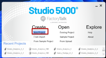
On the Studio 5000 start screen, locate the Create section and select New Project. This option opens the wizard used to define the controller family, catalog number, and revision for the application.
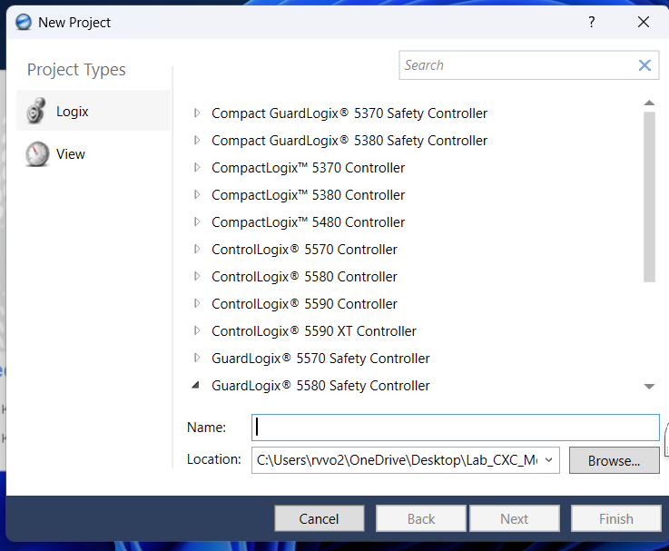
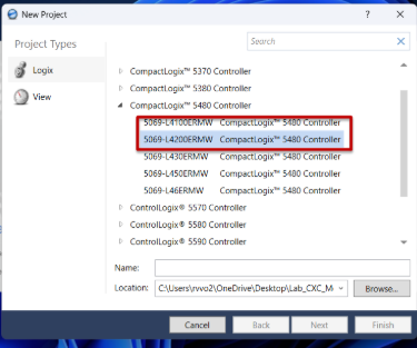
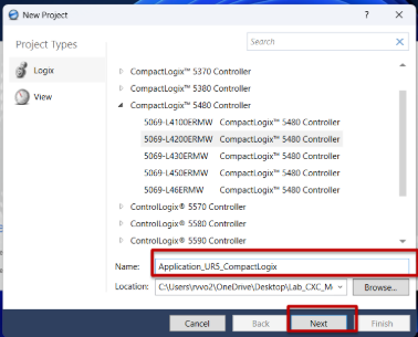
Under Project Types, select Logix and locate the CompactLogix 5480 Controller family.
Before completing the selection, confirm the catalog number and revision of the physical device. The following steps use FactoryTalk Linx to obtain this information.
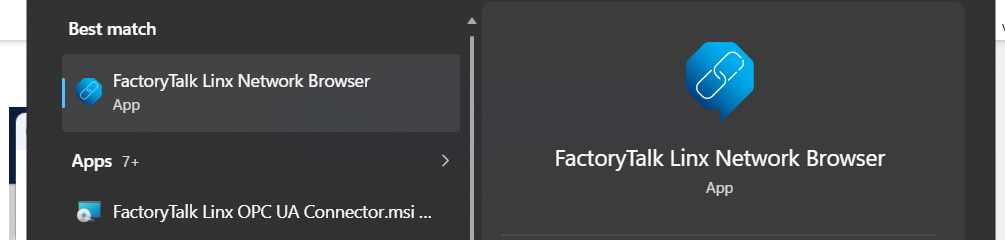
Open FactoryTalk Linx Network Browser from Windows. This tool detects available Rockwell Automation devices on the network and allows you to verify the actual CompactLogix model before creating the project.
In FactoryTalk Linx, expand the Ethernet adapter connected to the lab network. Locate the controller at address 192.168.1.102 and verify that it is a 5069-L4200ERMW before continuing.
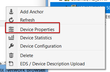
Right-click the detected controller and select Device Properties. This window contains the information required to correctly configure the new Studio 5000 project.
In Device Properties, confirm the controller catalog number and record the firmware revision shown for the device. The revision selected in Studio 5000 must be compatible with the revision installed in the CompactLogix before the project can be downloaded.
After confirming the physical device information, select CompactLogix 5480 Controller, catalog number 5069-L4200ERMW, assign the name Application_UR5_CompactLogix, and configure the project revision to match the controller. Retain the safety options required by your facility policy.
Return to Studio 5000 and, within the CompactLogix 5480 Controller family, select catalog number 5069-L4200ERMW. Make sure you select the exact model previously identified in FactoryTalk Linx.
In the Name field, enter “Application_UR5_CompactLogix” and confirm the folder where the project file will be stored. Then select Next to continue configuring the controller.
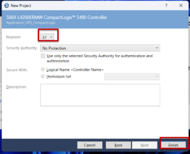
On the next screen, select a revision compatible with the revision installed in the physical controller. Retain the remaining safety parameters required for the lab, and select Finish to create the project.
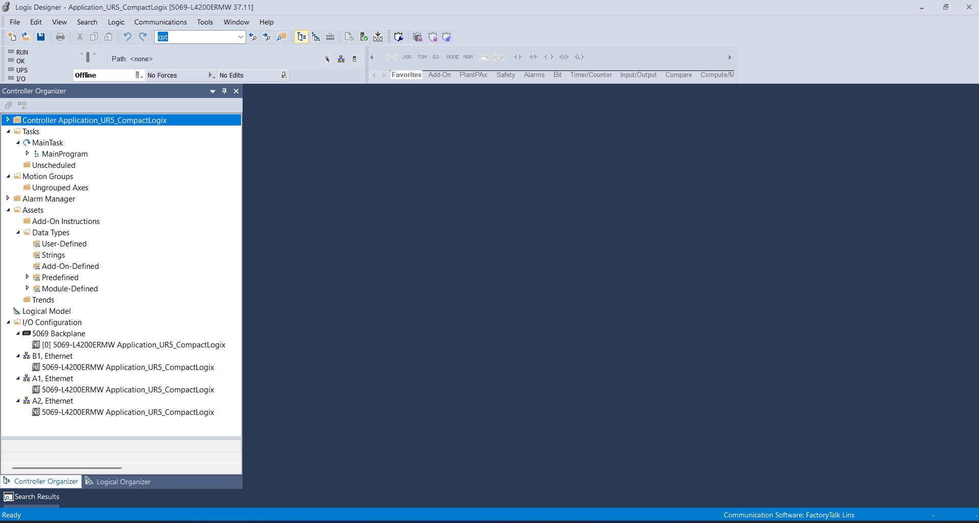
Wait for Studio 5000 to finish creating and opening the project. Verify that Controller Organizer displays the 5069-L4200ERMW controller and its Ethernet interfaces before continuing with the UR5 network configuration.
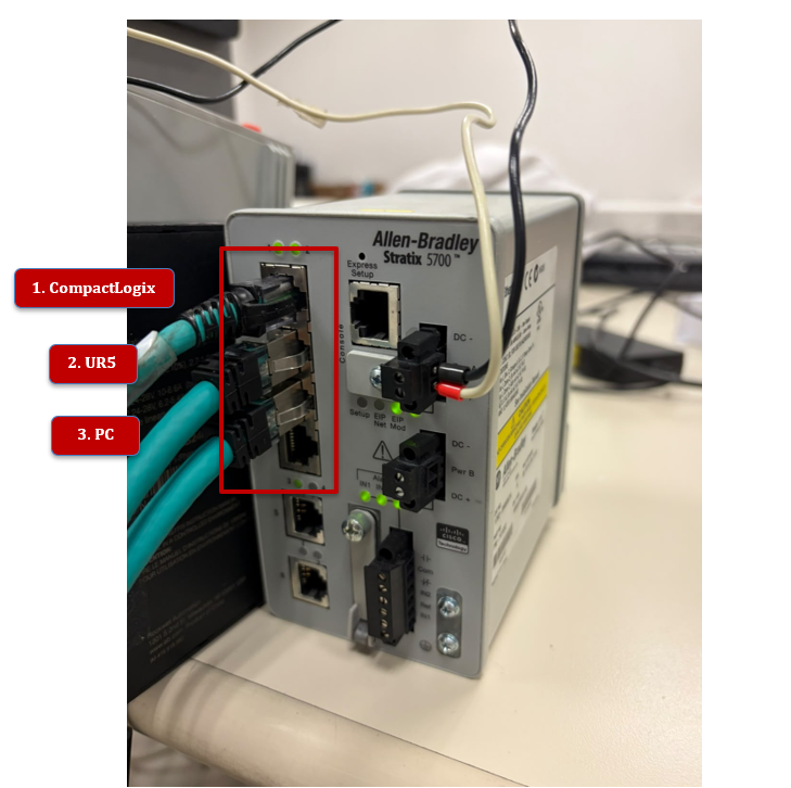
The network used for this application connects all three devices to a Stratix 5700. The CompactLogix is connected through LAN B1, while the UR5 and the PC share the same Ethernet network. The Stratix operates as a Layer 2 switch; therefore, it does not need to be added to the Studio 5000 I/O tree for basic communication between the PLC and the robot.
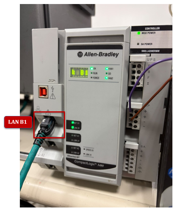
Physically verify that the Ethernet cable used for this application is connected to the CompactLogix B1 interface. Also confirm that the NET B1 and LINK B1 indicators show network activity.
Review the Stratix 5700 connections. For this application, connect the CompactLogix to port 1, the UR5 controller to port 2, and the engineering PC to port 3. Confirm that the LEDs for the ports in use indicate a link.
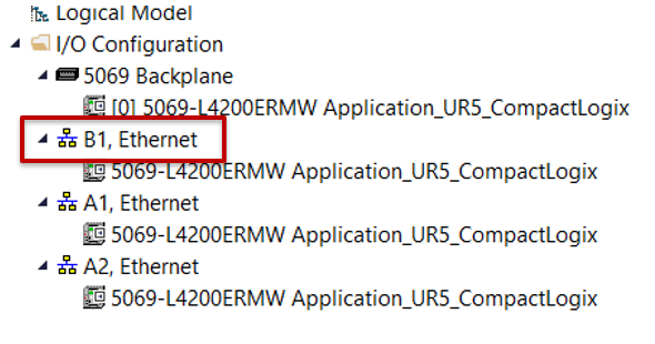
In Studio 5000, expand I/O Configuration and review the CompactLogix B1, A1, and A2 interfaces. The UR5 integration is performed under B1, Ethernet, because this is the interface physically used in the application.
NOTE: Verify that there are no duplicate IP addresses and that all three devices belong to the same subnet. The UR5 used here is a CB-Series robot with PolyScope 3; its menu layout differs from that of a UR5e with PolyScope 5.
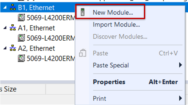
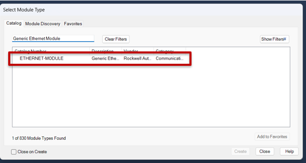
In I/O Configuration, right-click B1, Ethernet and select New Module. Search for Generic Ethernet Module and create an ETHERNET-MODULE. The CompactLogix will be the originator of the Class 1 connection, and the UR5 will operate as the adapter.
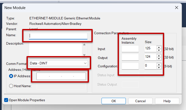
Right-click B1, Ethernet and select New Module. This adds the EtherNet/IP representation of the UR5 controller to the I/O tree.
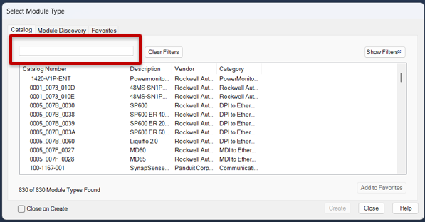
In the Select Module Type window, use the search box to filter the available modules. The objective is to use a generic Ethernet module that allows the assemblies defined by Universal Robots to be entered manually.
When the New Module window opens, review the default values without accepting them yet. In the next step, the communication format will be changed to SINT and the IP address and assemblies for the UR5 will be entered.
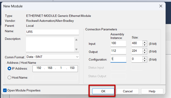
Configure the module using the assembly parameters defined by Universal Robots:
Parameter
Value
Name
UR5
Comm Format
Data - SINT
IP Address
192.168.1.150
Input Assembly Instance
100
Input Size
480 SINT / bytes
Output Assembly Instance
112
Output Size
224 SINT / bytes
Configuration Assembly Instance
1
Configuration Size
0
RPI
10 ms
Connection
Unicast over EtherNet/IP
Step 3.3
Configure the module with Name = UR5, Comm Format = Data - SINT, and IP Address = 192.168.1.150. Under Connection Parameters, enter Input Assembly 100 with Size 480, Output Assembly 112 with Size 224, and Configuration Assembly 1 with Size 0. Then select OK.
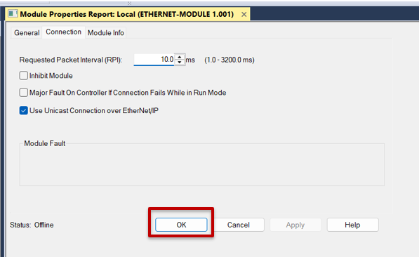
In Module Properties, open the Connection tab. Set the Requested Packet Interval to 10.0 ms, keep Use Unicast Connection over EtherNet/IP enabled, and leave Inhibit Module and Major Fault On Controller If Connection Fails While in Run Mode cleared. Select OK.
From the PLC perspective, Input is the information received from the UR5, and Output is the information sent by the CompactLogix to the robot. An RPI of 10 ms provides a sufficiently fast update for this demonstration without using the 2 ms minimum available in the device.
Download the project and align the A1/A2 Ethernet mode if required.
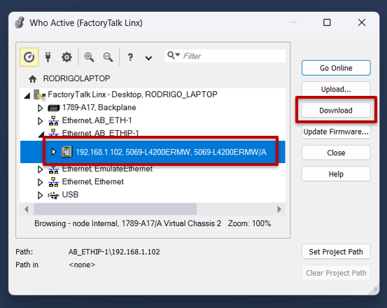
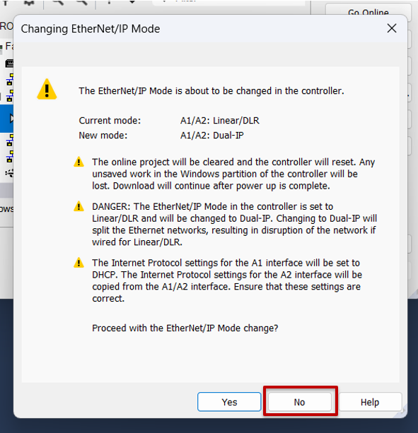
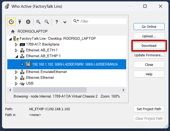
Open Who Active, select the CompactLogix at 192.168.1.102, and execute Download. Studio 5000 displays the standard download warning. If a second warning indicates that the project is attempting to change A1/A2 from Linear/DLR to Dual-IP, do not apply the change automatically for this application.
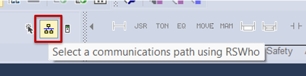
Open the communication path selector through Who Active. This window allows you to select the physical controller to which the newly configured project will be downloaded.
In Who Active, expand the Ethernet network and select the CompactLogix 5069-L4200ERMW at IP address 192.168.1.102. Verify that the displayed path points to the correct controller, and select Download.
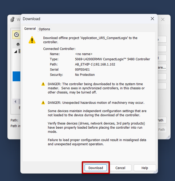
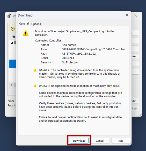
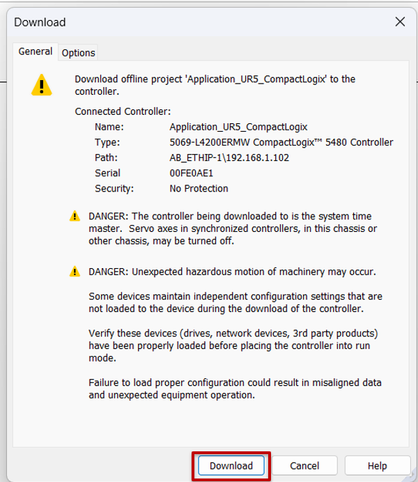
Review the warning displayed before the download and confirm that the work area is safe. If the selected controller, path, and project are correct, select Download to begin the transfer.
If Studio 5000 displays a warning that the A1/A2 mode in the project differs from the controller mode, do not accept the change automatically. Select No or cancel the download to review the configuration first, because this application uses B1 for communication with the UR5.
In this setup, communication with the UR5 uses B1, and ports A1/A2 are not used. Therefore, if the physical controller is already configured for Linear/DLR, cancel the download and modify the offline project so that A1/A2 are also set to Linear/DLR. This avoids unnecessarily changing the controller's existing topology.
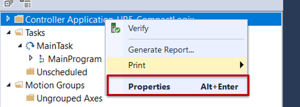
After canceling the download, right-click the controller name in Controller Organizer and select Properties. Use this window to align the project's A1/A2 configuration with the configuration of the physical device.
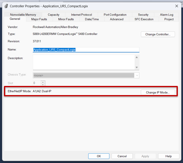
On the General tab of Controller Properties, locate the EtherNet/IP Mode field. If the project shows A1/A2: Dual-IP while the physical controller is set to Linear/DLR, select Change IP Mode to correct the mismatch.
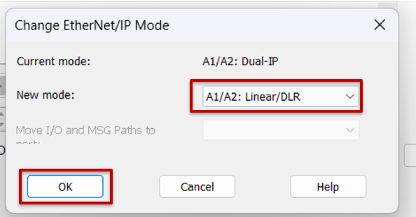
In Change EtherNet/IP Mode, select A1/A2: Linear/DLR and confirm with OK. This changes the project to match the controller's current mode without altering the B1 interface used by the UR5.
Select Download and review the standard warning again. With the A1/A2 mode now aligned, confirm the download to transfer the updated project to the controller.
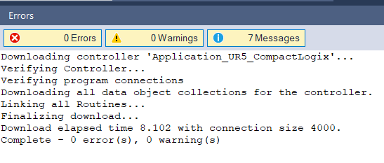
Wait for the download process to finish and review the message pane. The procedure must end with “Complete - 0 error(s), 0 warning(s)” before continuing with the UR5 configuration.
Repeat the download and confirm that the process finishes with 0 Errors and 0 Warnings. After the download, Studio 5000 can remain in Program Mode while the robot's EtherNet/IP adapter is enabled.
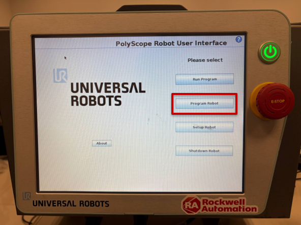
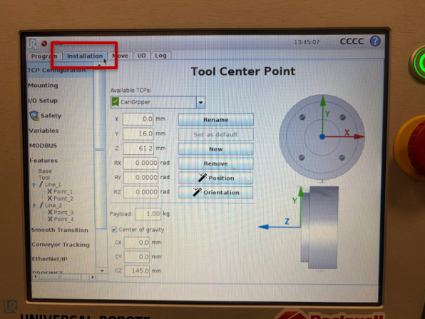
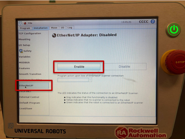
On the Teach Pendant, return to the PolyScope 3 main screen, select Program Robot, and open the Installation tab. In the side menu, select EtherNet/IP and press Enable. The indicator must turn green and display EtherNet/IP Adapter: Connected when the CompactLogix establishes the cyclic connection.
On the UR5 Teach Pendant, return to the PolyScope 3 main screen. If another program is open, use File > Exit and, from the main screen, prepare to access the robot programming environment.
Select Program Robot. This option opens the environment used to edit the robot installation and enable the EtherNet/IP adapter required for the CompactLogix connection.
In the robot editor, select the Installation tab. The left pane displays the installation configuration options, including the available communication buses.
In the Installation side menu, select EtherNet/IP. If the heading displays “EtherNet/IP Adapter: Disabled,” press Enable to activate the UR5 communication adapter.
Wait a few seconds after enabling the adapter. When the CompactLogix establishes the connection, the heading must change to “EtherNet/IP Adapter: Connected,” and the indicator must turn green.
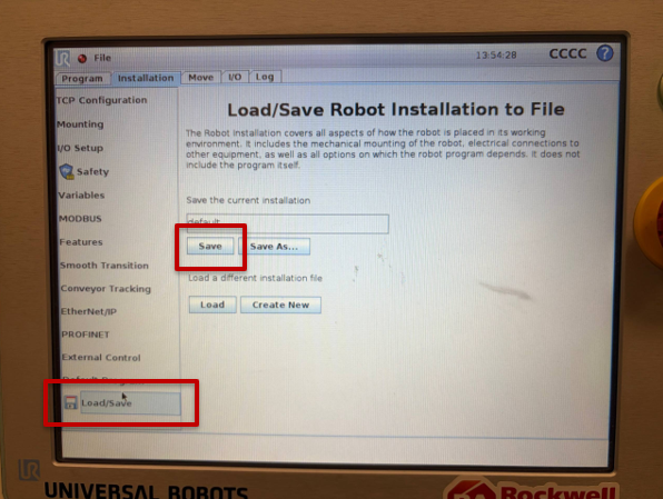
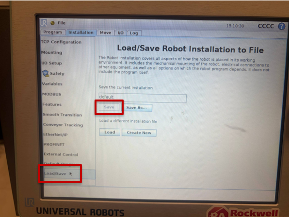
Save the installation under Installation > Load/Save. This retains the EtherNet/IP adapter setting the next time the installation is loaded.
With the adapter connected, open Installation > Load/Save. Press Save to store the current installation and retain EtherNet/IP enablement when this configuration is loaded again.
NOTE: If the PC can ping the UR5 but Studio 5000 reports 16#0204 Connection Request Error: Connection request timed out, first verify that the EtherNet/IP Adapter is enabled and that the module IP address and assemblies match the values in this guide.
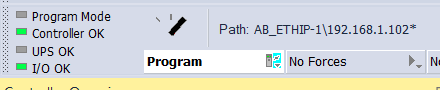
When the connection is established, Studio 5000 displays I/O OK. At this point, the generic module is exchanging 480 bytes of input data and 224 bytes of output data; however, the data appears as SINT arrays without visible meaning, for example UR5:I.Data[] and UR5:O.Data[].
Return to Studio 5000 and go online with the CompactLogix. Verify that the status at the top displays I/O OK. This confirms that the cyclic EtherNet/IP connection with the UR5 has been established correctly.
The “raw bytes” are simply the memory block transported by EtherNet/IP between the robot and the PLC. Each byte occupies a fixed position in the message map, but a SINT array alone does not identify which positions represent Robot Mode, Safety, Joint 1, TCP X, or an integer register. The UR_DataTypes.L5X file defines UDT structures with names and data types that reflect the official map. This allows the program to work with readable members instead of manually manipulating byte offsets.
Take the project offline, go to Data Types > User-Defined > Import Data Type, and select UR_DataTypes.L5X. The import adds 14 UDTs, including the combined T2O and O2T structures and their Robot, Safety, I/O, Tool, Joints, TCP, and general-purpose register substructures.
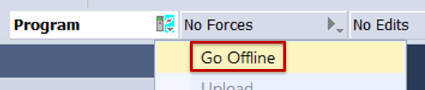
To import the new data types, take the project offline from the Studio 5000 mode menu. The following structural changes are made to the offline project and downloaded to the PLC later.
In Controller Organizer, expand Data Types > User-Defined. Right-click User-Defined and select Import Data Type to load the official Universal Robots structures.
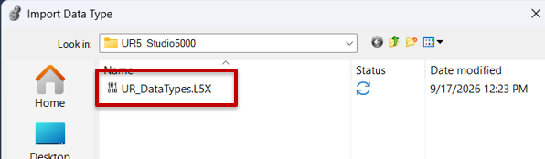
In the file browser, locate and select UR_DataTypes.L5X. This file contains the User-Defined Data Types that describe the format of the data exchanged with the UR5 through EtherNet/IP.
In Import Configuration, verify that the 14 Data Types to be imported are displayed and that no errors are present. Retain the original names and select OK to complete the import.
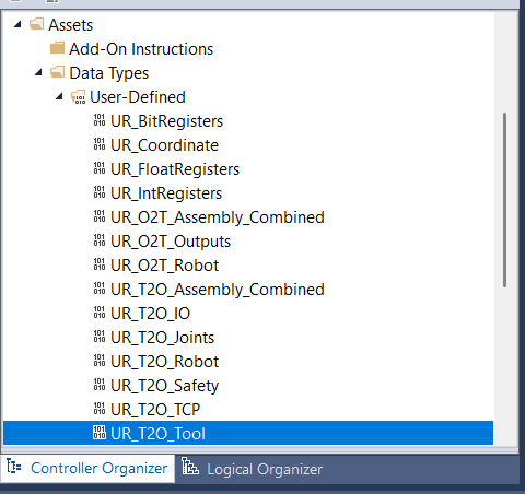
Expand Data Types > User-Defined again and verify that the Universal Robots UDTs appear, including UR_T2O_Assembly_Combined and UR_O2T_Assembly_Combined. These types allow the generic module bytes to be interpreted using readable names and structures.
Create URI/URO and map the UR5 input data with CPS.
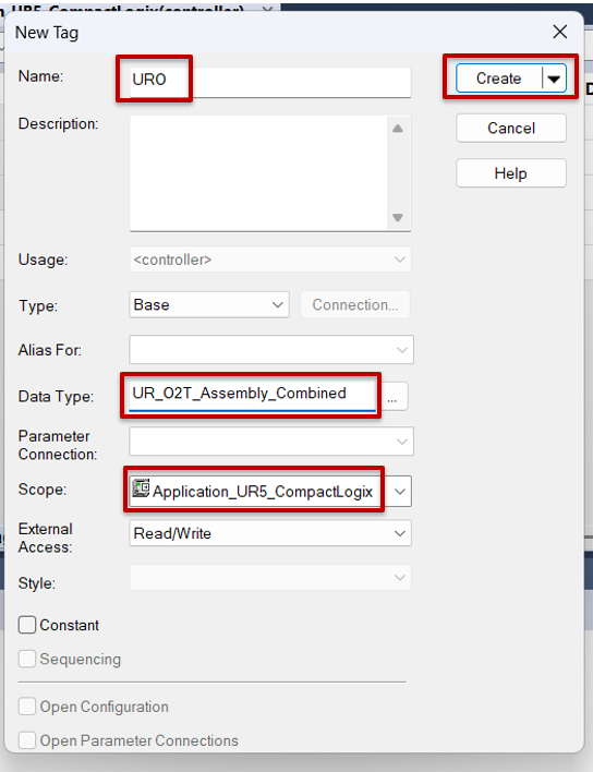
Create two Controller Tags using the imported types: URI with UR_T2O_Assembly_Combined and URO with UR_O2T_Assembly_Combined. T2O means Target to Originator and represents UR5 → CompactLogix. O2T means Originator to Target and represents CompactLogix → UR5.
Open Controller Tags to create the two working structures that represent the flow of information between the robot and the PLC. Use New Tag or Edit Tags to add the new tags at controller scope.
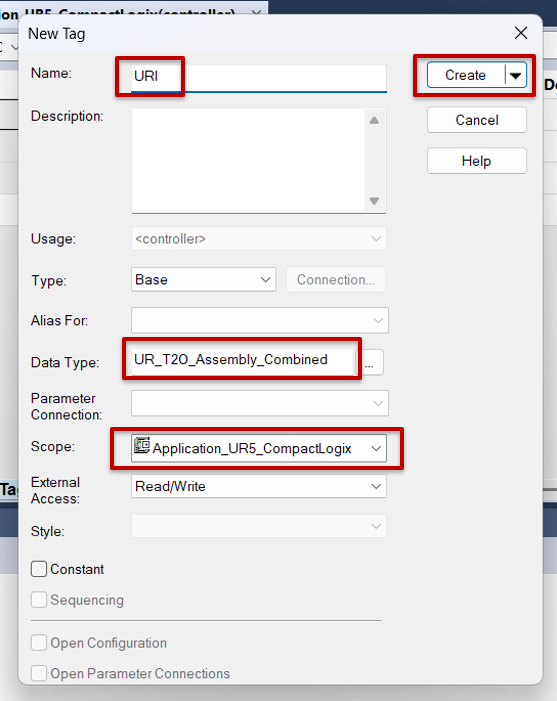
Create the URI tag and assign UR_T2O_Assembly_Combined as its Data Type. Keep the tag at controller scope; URI stores the information received from the UR5.
Create a second tag named URO with Data Type UR_O2T_Assembly_Combined. This structure will be used later to prepare the data that the CompactLogix sends to the robot.
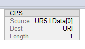
In MainRoutine, add a CPS instruction to copy the input assembly to the URI UDT. The instruction must execute continuously:
CPS
Source: UR5:I.Data[0]
Dest: URI
Length: 1
Step 7.3
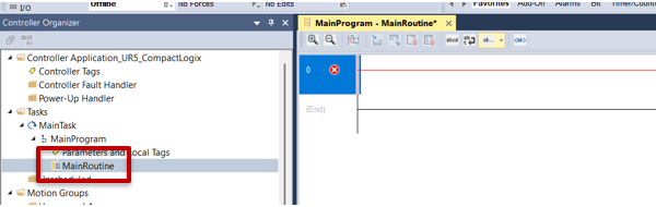
Open Tasks > MainTask > MainProgram > MainRoutine. Insert an available rung and prepare a copy instruction to transfer the EtherNet/IP input block to the URI structure.
Add a CPS instruction to the rung. CPS copies the data block synchronously, preventing the logic from reading a partially updated structure during the transfer.
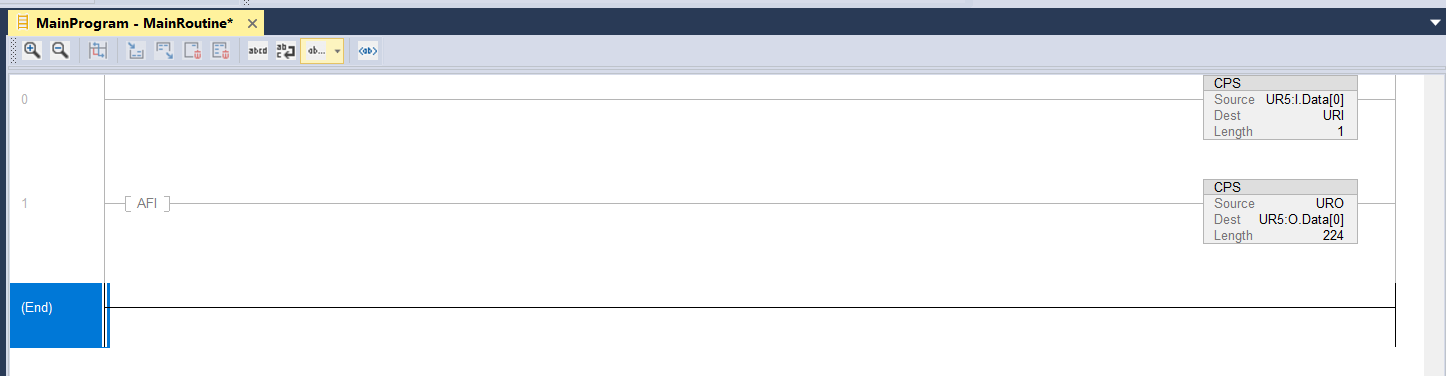
Configure the CPS with Source = UR5:I.Data[0], Dest = URI, and Length = 1. This instruction copies the complete input assembly from the UR5 module to the URI structure on every routine scan.
Length = 1 means that the destination is one complete UR_T2O_Assembly_Combined structure. CPS performs a synchronous copy to prevent the program from using a partially updated structure during the scan.
Download the project again. Set the physical CompactLogix mode switch to REM and change the controller to Remote Run from Studio 5000.
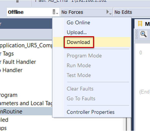
After adding the read logic, open the Studio 5000 mode menu and select Download to send the new configuration to the CompactLogix.Descargue nuevamente el proyecto. Coloque el selector
In the confirmation window, verify that the connected controller is the 5069-L4200ERMW used for this application. If the information is correct and the area is safe, select Download.
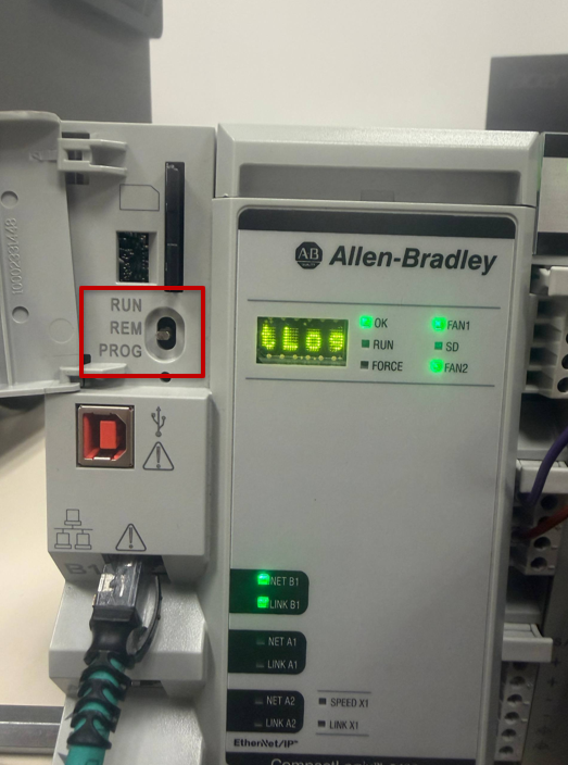
On the physical controller, open the mode-switch cover and set the switch to REM. This position allows Studio 5000 to change the controller between Remote Program and Remote Run without physically moving the switch again.
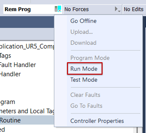
In Studio 5000, open the mode menu and select Run Mode. Because the physical switch is in REM, the option should be available to change the controller to Remote Run.
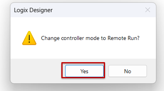
When Logix Designer requests confirmation to change to Remote Run, verify that the logic cannot cause unexpected operation, and select Yes to begin program execution.
Open Controller Tags and select the Monitor Tags tab. This view displays the values updated by the CPS instruction in real time while the controller is running.
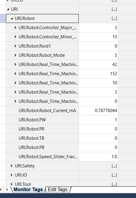
Expand URI and then URI.Robot. Verify that Controller Major and Controller Minor match the UR5 PolyScope version, and observe Robot_Mode to confirm that the information is being decoded correctly.
Validate and interpret the data received from the UR5.
Under Controller Tags > Monitor Tags, expand URI.Robot. During the test, Controller Major = 3 and Controller Minor = 15 were observed, consistent with PolyScope 3.15.4. The value Robot_Mode = 5 corresponds to the robot's IDLE status under this test condition. This match confirms that the CPS is correctly aligning the byte map with the UDTs.
The most useful branches for monitoring are:
Group
Primary information
Why it matters
URI.Robot
Version, Robot Mode, program status, current, and speed slider.
Shows overall status and confirms that the robot is in the expected mode before coordinating a sequence.
URI.Safety
Safety Mode and Normal, Reduced, Protective Stop, E-Stop, Safeguard, Fault, and other bits.
Supports diagnostics and process interlocks. It does not replace a certified safety function.
URI.Joints
Position, speed, current, temperature, and mode for all six joints.
Supports monitoring of movement, joint position, and the condition of each axis.
URI.TCP
TCP XYZ position, RX/RY/RZ orientation, speed, force, and torque.
Supports monitoring of the tool's Cartesian pose and coordination of the application with the machine.
URI.IO / URI.Tool
Inputs, outputs, and tool signals.
Useful for diagnostics and for sharing the status of robot sensors or actuators.
URI.Bit / URI.Int / URI.Float
General-purpose fieldbus registers.
Flexible channel for handshakes, recipes, commands, and parameters between the PLC and PolyScope.
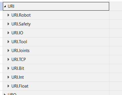
Return to the main URI level and review the available branches: Robot, Safety, I/O, Tool, Joints, TCP, Bit, Int, and Float. These structures organize the data received from the robot and simplify its use in control and diagnostic logic.
To transmit data to the robot, add a second CPS that copies the URO structure to the output assembly. During initial preparation, place an AFI before the CPS to keep writing disabled until the PolyScope test program is complete.
To prepare the CompactLogix → UR5 direction, return to MainRoutine and insert a second rung. Temporarily place an AFI at the beginning of the rung and add a CPS after it. The AFI keeps the output copy disabled while configuration is being completed.
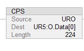
Configure the second CPS with Source = URO, Dest = UR5:O.Data[0], and Length = 224. Keep the AFI ahead of the instruction to prevent the PLC from writing the output assembly before the UR5 test program is created.
The value 224 corresponds to the 224 SINTs/bytes of the Output Assembly configured in the Generic Ethernet Module. While the AFI is present, values prepared in URO are not copied to UR5:O.Data[].
Create a PolyScope test program to read an integer register.
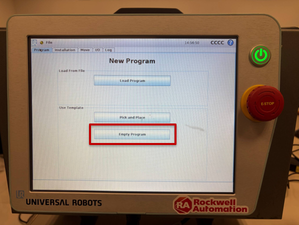
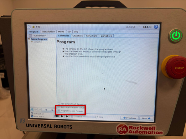
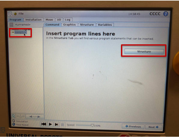
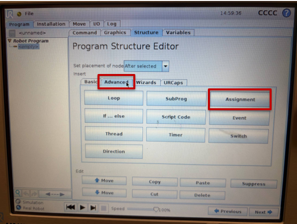
On the Teach Pendant, create an Empty Program and verify that Program Loops Forever remains enabled. Select the <empty> node, open Structure, and insert an Assignment under Advanced.
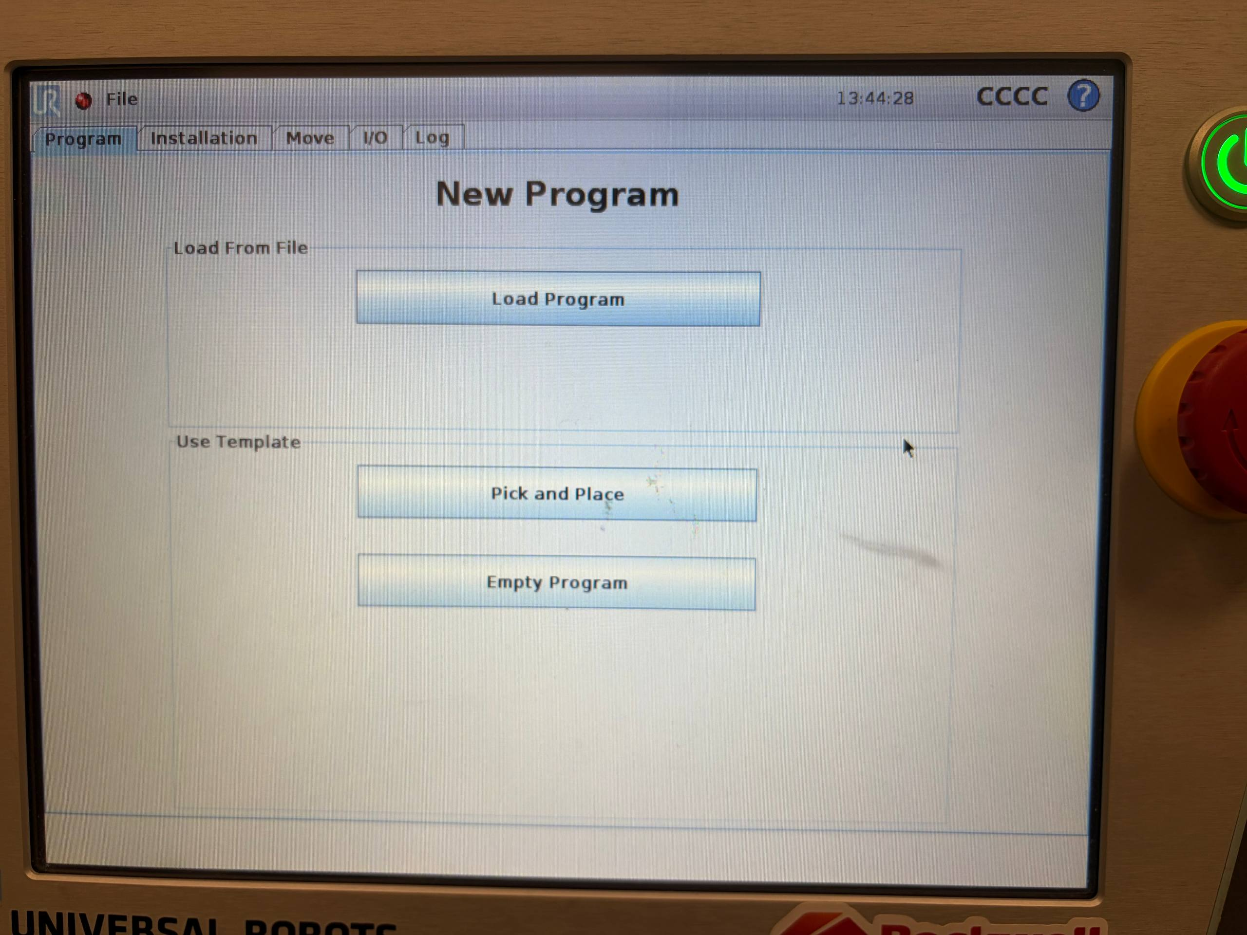
On the Teach Pendant, open Program Robot and select Empty Program. A simple new program is created that only reads an EtherNet/IP register and contains no motion instructions.
Select Robot Program in the tree and confirm that Program Loops Forever is enabled. This option repeats the register read continuously while the program is running.
In Structure, open the Advanced tab and select Assignment. This adds an assignment line to the UR5 program for storing the value received from the PLC.
Integer registers 0…23 belong to the range reserved by Universal Robots for Fieldbus/PLC interfaces. This test uses register 23 to avoid interfering with registers that may be used by other robot programs.
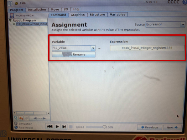
Select the new Assignment and, under Command, create or select the PLC_Value variable. Under Expression, enter read_input_integer_register(23) to read integer register 23, which is reserved for the Fieldbus/PLC interface.
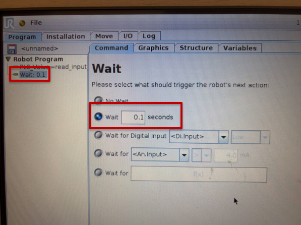
Add a Wait of 0.1 s. The delay is not required for EtherNet/IP, but it simplifies the test and prevents the assignment from executing at the maximum PolyScope cycle rate.
Add a Wait instruction after the Assignment and set the time to 0.1 s. The program reads PLC_Value cyclically, with a short pause between iterations to make the test easier to observe.
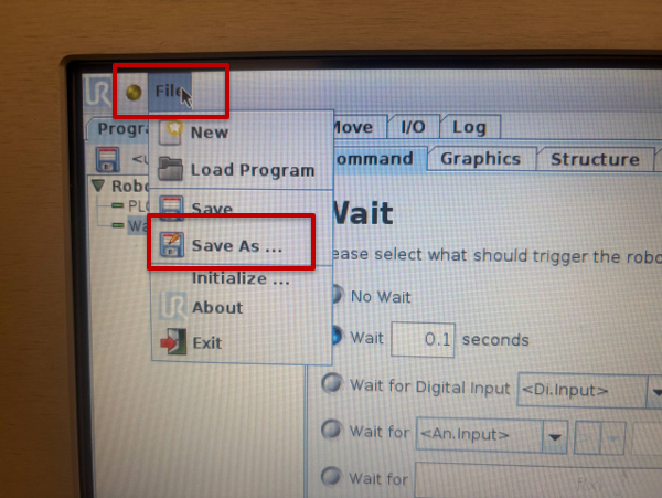
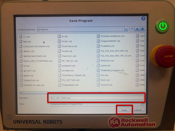
Save the program using File > Save As with the name PLC_EIP_Test.urp, and confirm that the robot installation is also saved.
Open the File menu in the upper-left corner of the Teach Pendant and select Save As. This option saves the test program under a name that is independent of other programs already on the robot.
Open Installation > Load/Save and review the installation status. If the Save button is enabled, press it to store any pending changes. If it is disabled, the installation is already saved.
Replace the AFI with controlled write enable logic.
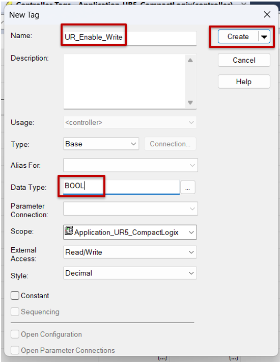
In Studio 5000, create a BOOL Controller Tag named UR_Enable_Write. Replace the AFI in the output rung with an XIC associated with this tag. This allows writing to the UR5 to be enabled or blocked without modifying the logic during testing.
In Studio 5000, open Controller Tags and create a new BOOL tag named UR_Enable_Write. This bit is used as an explicit permission to enable or block writes from the CompactLogix to the UR5.
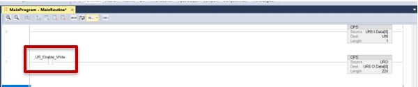
Return to MainRoutine and replace the AFI in the output rung with an XIC associated with UR_Enable_Write. Initially leave the bit at 0 so that the output CPS remains disabled until the test.
IMPORTANT: Before enabling UR_Enable_Write, keep the Speed Slider and physical output masks in URO at zero if you do not want to take control of those resources. This test modifies only URO.Int.Registers[23].
Download the project, leave the controller in Remote Run, and enter the value 123 in URO.Int.Registers[23].
Download the updated project, place the controller in Remote Run, and open Controller Tags > Monitor Tags. Expand URO.Int.Registers and enter the value 123 in URO.Int.Registers[23], while keeping UR_Enable_Write at 0.
Run the UR5 test and validate bidirectional communication.
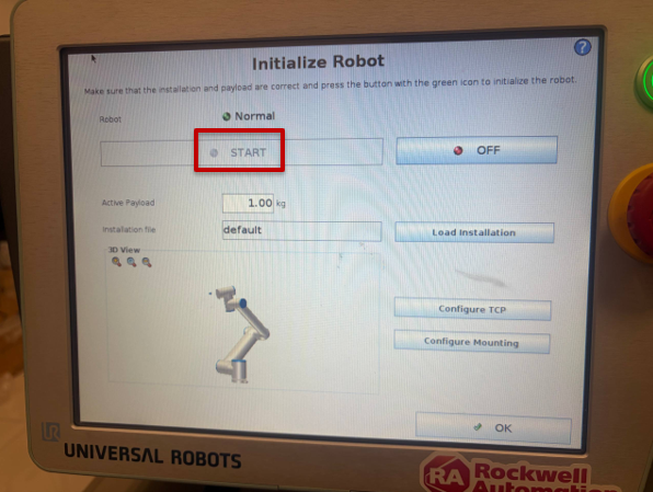
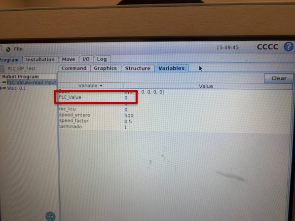
On the Teach Pendant, initialize the robot until it reaches START, load PLC_EIP_Test, and press Play. On the Variables tab, observe PLC_Value. Before enabling the output CPS, the value may remain at 0.
On the Teach Pendant, initialize the robot and verify that the screen shows Normal status and that the START button allows initialization to complete. Robot-arm movement is not required for this test, but the robot must be properly initialized to execute the program.
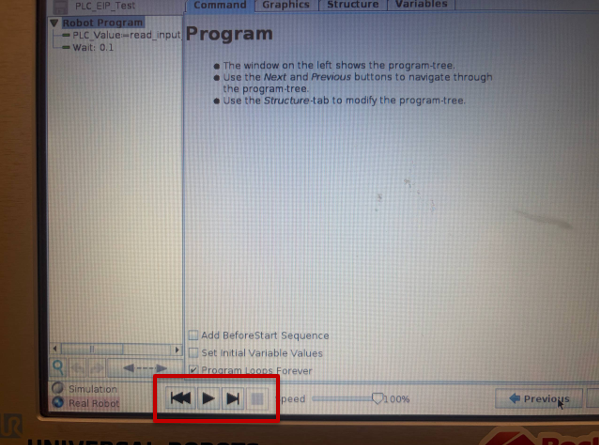
Load PLC_EIP_Test if it is not active, and press the Play button at the bottom of the Teach Pendant. The program begins repeatedly executing the Assignment and the configured Wait.
With the program running, open the Variables tab and locate PLC_Value. Before enabling the PLC write, confirm the displayed value. In the initial test, the value is 0 because the output CPS is still blocked.
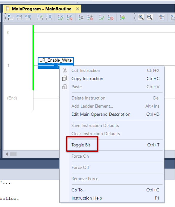
Return to Studio 5000 and enable UR_Enable_Write using Toggle Bit. The XIC becomes true and the CPS begins copying URO to UR5:O.Data[0]. The value 123 sent in URO.Int.Registers[23] is received by the UR5, and the read_input_integer_register(23) instruction updates PLC_Value.
Return to Studio 5000 and, while online, right-click the UR_Enable_Write XIC and select Toggle Bit, or change the tag to 1 from Monitor Tags. When the XIC is enabled, the CPS begins copying URO to UR5:O.Data[0].
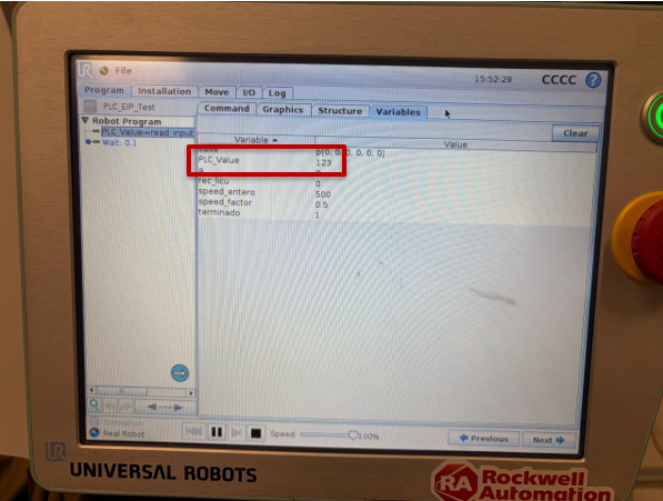
Return to the Variables tab on the Teach Pendant and observe PLC_Value. The value must change to 123, demonstrating that URO.Int.Registers[23] was sent through EtherNet/IP and read correctly by read_input_integer_register(23).
PLC_Value = 123 on the Teach Pendant validates the return path. Both UR5 → CompactLogix through URI and CompactLogix → UR5 through URO are now verified.
The completed application establishes bidirectional EtherNet/IP communication between a CompactLogix 5480 and a UR5 CB-Series robot. URI receives and decodes robot information, while URO sends registers to PolyScope. The integer-register test confirms that the network configuration, assemblies, UDTs, and CPS instructions work together correctly.
Validation
Expected result
IP connectivity
PLC, UR5, and PC accessible on the 192.168.1.x network.
UR5 EtherNet/IP
Adapter: Connected with a green indicator.
Studio 5000
Controller OK and I/O OK.
UR5 → PLC
URI.Robot, URI.Safety, URI.Joints, and URI.TCP display valid data.
PLC → UR5
With UR_Enable_Write active, PLC_Value matches URO.Int.Registers[23].
This foundation supports Ready, Start, Busy, Done, and Fault handshakes, as well as recipe or task selection. For production, assign registers clearly, document the handshake, and validate behavior during communication loss, restarts, and safety-state changes.
EtherNet/IP Integration Between CompactLogix and UR5 Cobot
Version 1.0 - October 2026
Receive new applications and Innovation Center updates directly in your inbox.