Loading
View all Solid-state Temperature Sensors
Print
Share
QR code
JSON
  • alt text
alt text
Chevron LeftChevron Left
alt text
Chevron LeftChevron Left
Allen-Bradley logo
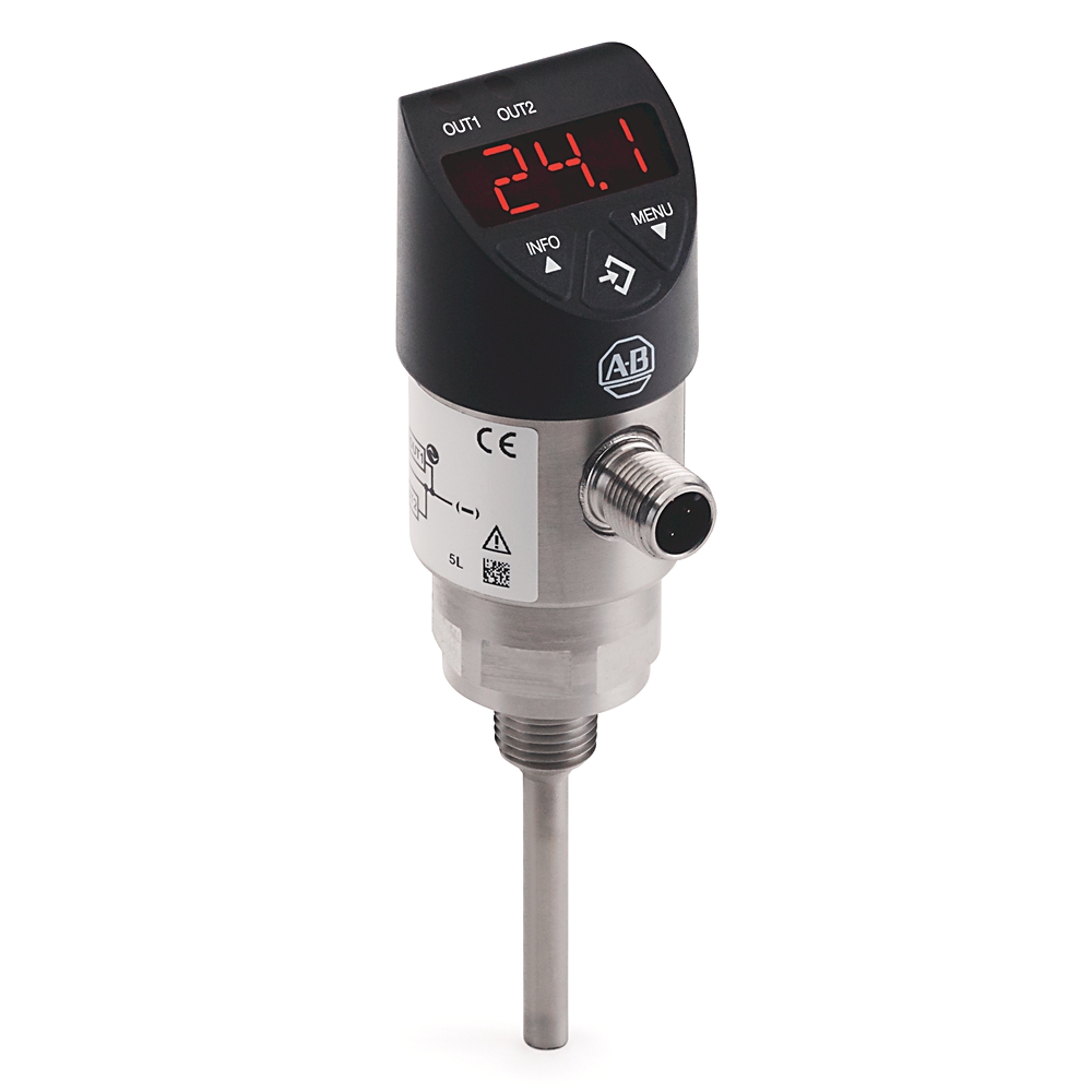
837T-D3N14B10PP-D4

Solid-State Temperature Sensor

Serial #:
This product has not been verified. Please {} to confirm authenticity. register your product
Lifecycle status: Active
Description
Solid-State Temperature Sensor, Standard, Display/ Push-button, -4 ... +176 F / -20 ... +80 C, 1/4 NPT - Male, 100 mm, 2 PNP - IO-Link, 4-Pin DC Micro(M12) Integral QD
  • Add to BOM
  • Repair services
  • Get support
837T-D3N14B10PP-D4

Solid-State Temperature Sensor

Serial #:
This product has not been verified. Please {} to confirm authenticity. register your product
  • alt text
alt text
Chevron LeftChevron Left
alt text
Chevron LeftChevron Left
Allen-Bradley logo
Lifecycle status: Active
Description
Solid-State Temperature Sensor, Standard, Display/ Push-button, -4 ... +176 F / -20 ... +80 C, 1/4 NPT - Male, 100 mm, 2 PNP - IO-Link, 4-Pin DC Micro(M12) Integral QD
  • Add to BOM
  • Repair services
  • Get support
Find your nearest distributor
Contact your distributor in {0}
Change location
PhonePhone
Find a partner
Find your nearest distributor
Contact your distributor in {0}
Change location
PhonePhone
Find a partner
Overview
Technical Specifications
Performance & Accuracy
Compliance & Environment
Standards & Protection
Environmental Operating Conditions
Electrical Safety
Electrical & Connectivity
Power & Electrical Characteristics
Inputs & Outputs (I/O)
Physical Characteristics
Mechanical
Construction
Material
Drawings
Documents
Accessories
Alternative Products
Technotes
Unique Product Identifier
837T-D3N14B10PP-D4
UPC
889508092942
Estimated Lead Time
5 days
Standard Warranty Duration

1 year See details

Country of Origin
Germany
Adjustment accuracy switching points
≤ ±0.5% of span
Analog signal
≤ ±0.5% of span ± temperature sensor error
Display
≤ ±0.8% of span ± temperature sensor error ±1 digit
Load
Analog signal 4...20 mA: ≤0.5 kΩ
Scaling analog signal
0...25% of span, Full scale: 75...100% of span
Switching output
≤ ±0.8% of span ± temperature sensor error
Temperature error
(0.15 + 0.002 (t - 32)/1.8) for fahrenheit
Ambient temperature
-20 °C
Reverse polarity protection
V+ vs. V-
Storage temperature
-20 °C
Temperature measuring range
-20 °C
Atmospheric pressure
950 mbar
Humidity
45...75 % r. h.
Nominal position
Process connection lower mount (LM)
Operating pressure
150 bar (2175 psi) maximum, with high temperature model (compression fitting is included) 50 bar (725 psi) at 120 °C (248 °F)
Power supply
24V DC
Temperature range
15 to 25 °C (59-77 °F)
Insulation voltage
500V DC
Overvoltage protection
40V DC
Short circuit protection
4...20 mA, out 1/out 2 vs. V-
Application
Measurement and monitoring of set temperatures
Current consumption
Switching outputs with: analog signal 4...20mA @ 70mA, without analog signal: 45 mA
Display type
Display/push button
Element measurement
Pt1000, 2-wire, DIN EN 60751/Class A
Process connection
1/2 NPT male
Output Signals
Output mode
Selectable - normally open, normally closed, window, hysteresis
Output threshold
OUT 1 and OUT 2 are individually adjustable
Output type
IO-link™ - Version 1.1 (Pin 4). With the IO-link option, switching output OUT 1 is always PNP
Output voltage
Power supply -1 V
Rated output current
OUT 1 maximum 100 mA, OUT 2 maximum 250 mA
Response time
T05 <5 s (per DIN EN 60751), T09 <10 s (per DIN EN 60751)
Service life
100000000 switching cycles
Zero offset adjustment
Maximum 3% of span
Mechanical
Diameter measuring insert
6 mm
Ingress rating
IP65 and IP67. The stated ingress protection (per IEC 60529) only applies when plugged in with mating connectors that have the appropriate ingress protection
Length measuring insert
100 mm
Shock
50 G (1.76 oz) (IEC 60068-2-27, mechanical)
Vibration
Probe Length ≤150 mm (5.91 in): 6 G (0.21 oz) (IEC 60068-2-6, under resonance), Probe Length ≥250 mm (9.84 in): 2 G (0.07 oz) (IEC 60068-2-6, under resonance)
Construction
Connection type
4 pin DC micro (M12)
Construction
Display head material
Personal computer + ABS-blend
Display window material
Polycarbonate
Housing material
Stainless Steel 304
Keyboard material
TPE-E
Temperature sensor material
Stainless Steel 316Ti
Drawings
3D STEP Model (STP) Download (ZIP)
Product Drawing Drawing (DWG)
Drawings
3D STEP Model (STP) Download (ZIP)
Product Drawing Drawing (DWG)
General Publication
Product Specifications --
Product Cutsheet --
Installation Instructions Publication
837t-in002_-en-p 837T-IN002
Looking for more documentation?
Find curated technical documentation for this product in the Technical Documentation Center, or search our full Literature Library.
Search the Literature Library
Items Per Page:
1-1 of 1
Items Per Page:
1-1 of 1
Technotes
Looking for more Technotes?
Find questions and answers from Rockwell Automation technical experts for this product in our Knowledgebase.
Search Knowledgebase
Overview
Unique Product Identifier
837T-D3N14B10PP-D4
UPC
889508092942
Estimated Lead Time
5 days
Standard Warranty Duration

1 year See details

Country of Origin
Germany
Technical Specifications
Adjustment accuracy switching points
≤ ±0.5% of span
Analog signal
≤ ±0.5% of span ± temperature sensor error
Display
≤ ±0.8% of span ± temperature sensor error ±1 digit
Load
Analog signal 4...20 mA: ≤0.5 kΩ
Scaling analog signal
0...25% of span, Full scale: 75...100% of span
Switching output
≤ ±0.8% of span ± temperature sensor error
Temperature error
(0.15 + 0.002 (t - 32)/1.8) for fahrenheit
Compliance & Environment
Ambient temperature
-20 °C
Reverse polarity protection
V+ vs. V-
Storage temperature
-20 °C
Temperature measuring range
-20 °C
Atmospheric pressure
950 mbar
Humidity
45...75 % r. h.
Nominal position
Process connection lower mount (LM)
Operating pressure
150 bar (2175 psi) maximum, with high temperature model (compression fitting is included) 50 bar (725 psi) at 120 °C (248 °F)
Power supply
24V DC
Temperature range
15 to 25 °C (59-77 °F)
Insulation voltage
500V DC
Overvoltage protection
40V DC
Short circuit protection
4...20 mA, out 1/out 2 vs. V-
Electrical & Connectivity
Application
Measurement and monitoring of set temperatures
Current consumption
Switching outputs with: analog signal 4...20mA @ 70mA, without analog signal: 45 mA
Display type
Display/push button
Element measurement
Pt1000, 2-wire, DIN EN 60751/Class A
Process connection
1/2 NPT male
Output Signals
Output mode
Selectable - normally open, normally closed, window, hysteresis
Output threshold
OUT 1 and OUT 2 are individually adjustable
Output type
IO-link™ - Version 1.1 (Pin 4). With the IO-link option, switching output OUT 1 is always PNP
Output voltage
Power supply -1 V
Rated output current
OUT 1 maximum 100 mA, OUT 2 maximum 250 mA
Response time
T05 <5 s (per DIN EN 60751), T09 <10 s (per DIN EN 60751)
Service life
100000000 switching cycles
Zero offset adjustment
Maximum 3% of span
Physical Characteristics
Mechanical
Diameter measuring insert
6 mm
Ingress rating
IP65 and IP67. The stated ingress protection (per IEC 60529) only applies when plugged in with mating connectors that have the appropriate ingress protection
Length measuring insert
100 mm
Shock
50 G (1.76 oz) (IEC 60068-2-27, mechanical)
Vibration
Probe Length ≤150 mm (5.91 in): 6 G (0.21 oz) (IEC 60068-2-6, under resonance), Probe Length ≥250 mm (9.84 in): 2 G (0.07 oz) (IEC 60068-2-6, under resonance)
Construction
Connection type
4 pin DC micro (M12)
Construction
Display head material
Personal computer + ABS-blend
Display window material
Polycarbonate
Housing material
Stainless Steel 304
Keyboard material
TPE-E
Temperature sensor material
Stainless Steel 316Ti
Drawings
Drawings
3D STEP Model (STP) Download (ZIP)
Product Drawing Drawing (DWG)
Drawings
3D STEP Model (STP) Download (ZIP)
Product Drawing Drawing (DWG)
Documents
Product Specifications General
--
Product Cutsheet General
--
837t-in002_-en-p Installation Instructions
837T-IN002
General Publication
Product Specifications --
Product Cutsheet --
Installation Instructions Publication
837t-in002_-en-p 837T-IN002
Looking for more documentation?
Find curated technical documentation for this product in the Technical Documentation Center, or search our full Literature Library.
Search the Literature Library
Accessories
Items Per Page:
1-1 of 1
Alternative Products
Items Per Page:
1-1 of 1
Technotes
Technotes
Looking for more Technotes?
Find questions and answers from Rockwell Automation technical experts for this product in our Knowledgebase.
Search Knowledgebase
InformationInformation
Multiple countries of origin based on manufacturing location

Solid-State Temperature Sensor
CloseClose
837T-D3N14B10PP-D4
Close
Print
Phone:
Call
InformationInformation

Please review your distributor selection

Choose distributor
Rockwell Automation Home
Copyright ©2026 Rockwell Automation, Inc.
Environmental compliance inquiry
All fields with * are required.
This field is required
Your inquiry has been successfully submitted.
Please allow up to 5 business days to receive a response to your inquiry.
You can now close this window.
There was an error submitting your inquiry.
Please try again.
Sign in to your Rockwell Automation account to submit a repair documentation request.
Sign In
Request repair documentation
All fields with * are required for processing your request.
Please enter your business email address
This field is required
Documentation of liability insurance is required for anyone who is requesting documentation for product repairs.
UploadUpload
Please upload documentation of Liability Insurance, Professional Establishment, and Technical Competence for the applicable EU Member Country.*
Accepted file types: zip, pdf. Max file size: 5 MB. Limit 3 files.
CloseClose
File size is too large. Must be less than 5 MB.
File limit exceeded. Maximum 3 files allowed.
This field is required
Right to Repair Terms and Conditions
Rockwell Automation is making, parts, and service documentation available at your request in compliance with applicable right to repair laws and regulations. By signing below, you are agreeing to the following terms and conditions of your purchase of Rockwell Automation genuine repair parts for repair of a Rockwell Automation product. As used below, “Self Service Repair Parts” means genuine Rockwell Automation parts (components of Rockwell Automation products) purchased from Rockwell Automation for installation in a Rockwell Automation product as part of a Self Service Repair. Self Service Repair Parts may be new or previously used genuine Rockwell Automation parts that have been tested and passed Rockwell Automation functional requirements. “Self Service Repair Tools” means equipment and related materials purchased for the purpose of performing repairs.
This field is required
Your request has been successfully submitted.
Please allow up to 5 business days to receive a response to your inquiry.
You can now close this window.
This catalog number is not currently eligible, please check the number you have entered or learn more about our repair services offered.
  1. Chevron LeftChevron Left Rockwell Automation Home
  2. Chevron LeftChevron Left Products
Please update your cookie preferences to continue.
This feature requires cookies to enhance your experience. Please update your preferences to allow for these cookies:
  • Social Media Cookies
  • Functional Cookies
  • Performance Cookies
  • Marketing Cookies
  • All Cookies
You can update your preferences at any time. For more information please see our {0} Privacy Policy
CloseClose