View all Solid-state Pressure Sensors
836P-D2NMGB14PP-D4
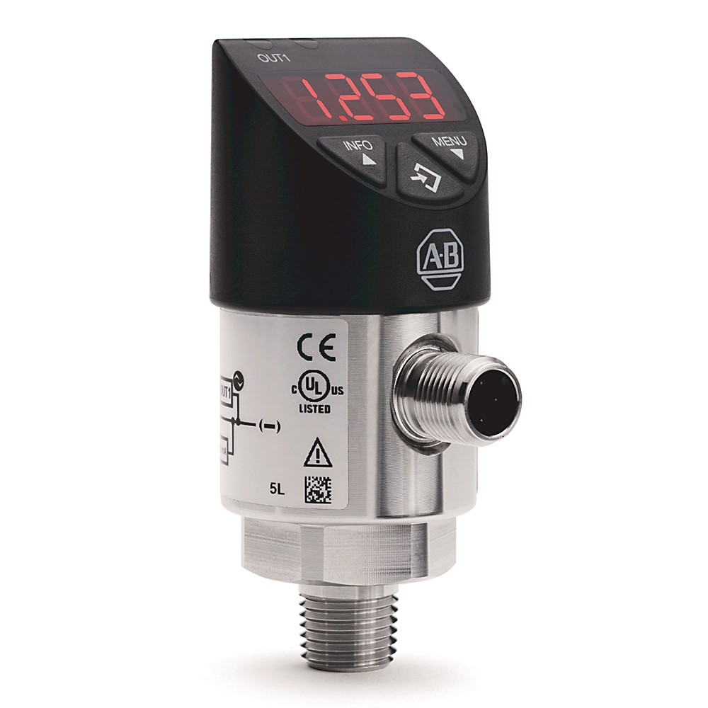
Standard Solid-State Pressure Sensor
Serial #:
This product has not been verified. Please register your product to confirm authenticity.
Lifecycle status:
Active
Lifecycle status:
Active
Technical Specifications
General
Construction
Mechanical
Electrical
Environmental
Drawings
Documents
Accessories
Alternative Products
Technotes
| Model Type |
Standard
|
|---|---|
| Upper Pressure Range |
145 psi
|
| With display |
True
|
|---|---|
| Readable |
True
|
| Housing material |
Stainless steel
|
| Position, nom |
Process connection lower mount (LM)
|
| Suitable for gases |
True
|
| Suitable for water |
True
|
| Suitable for steam |
True
|
| Suitable for air |
True
|
| Measuring element |
Piezo
|
| Sensor model |
Standard
|
| Connection type |
4 pin DC micro (M12)
|
| Display |
≤±1% of span ±1 digit
|
| Material |
Wetted parts: process connection: Stainless Steel 316 L, pressure sensing elements: <9.8 bar: Stainless Steel 316 L, ≥9.8 bar: Stainless Steel 13-8 PH, non-wetted parts: housing: Stainless steel 304, keyboard: TPE-E, display window: Polycarbonate, display
|
| Degree of protection (IP) |
IP67
|
|---|---|
| Upper pressure range |
145 psi
|
| Pressure type |
Gauge
|
| Thread size |
1/4 NPT male
|
| Service life |
100000000 switching cycles
|
| Shock |
50 G (1.76 oz) (IEC 60068-2-27, mechanical)
|
| Ingress rating |
IP65 and IP67. The stated ingress protection (per IEC 60529) only applies when plugged in with mating connectors that have the appropriate ingress protection
|
| Zero offset adjustment |
Maximum 3% of span
|
| Output signal |
Other
|
|---|---|
| Power supply |
15…35V DC
|
| Lower pressure range |
0 psi
|
| Reverse polarity protection |
V+ vs. V-
|
| Output type |
2xPNP IO-link
|
| Long term drift |
≤±0.2% of span (IEC 61298-2)
|
| Non-linearity |
≤±0.5% of span (BFSL, IEC 61298-2)
|
| Settling time |
Switching output : 20 ms with IO-link
|
| Current consumption |
With IO-Link: maximum 450 mA including switching current
|
| With temperature sensor |
False
|
| Cycle time, min |
3 ms
|
| Data storage support |
True
|
| Overvoltage protection |
40V DC
|
| Insulation voltage |
500V DC
|
| IO-link protocol |
Version 1.1
|
| Output voltage |
Power supply -1 V
|
| Rate |
COM2 (38.4 k Baud)
|
| Process data length |
16 bit (frame 2.2)
|
| Short circuit protection |
4...20 mA, Out 1/Out 2 vs. V-
|
| Output threshold |
OUT 1 and OUT 2 are individually adjustable
|
| Rated output current |
With IO-link : OUT1 maximum 100 mA, OUT2 maximum 250 mA
|
| Output mode |
Selectable - normally open, normally closed, window, hysteresis
|
| Switching output |
Switch point accuracy: ≤±1% of span, adjustment accuracy: ≤±0.5% of span
|
| Operating temperature |
15 °F
|
|---|---|
| Storage temperature |
-20 °F
|
| Atmospheric pressure |
950 mbar
|
| Ambient temperature |
-20 to 80 °C (-4 to 176 °F)
|
| Temperature error |
In rate temperature range: typical: ≤±1% of span, maximum: ≤±2.5% of span
|
| Media |
-20 °C
|
| Humidity |
45...75 % r. h.
|
| Vibration |
10 G (0.35 oz) (IEC 60068-2-6, under resonance)
|
| Overpressure limit |
2 times. 1.7 times for the relative pressure measuring ranges 16 psi, 1000 psi, and 1500 psi
|
| Temperature coefficient |
In rated temperature range: mean TC zero point: ≤±0.2% of span/10 K (typical), mean TC span: ≤±0.1% of span/10 K (typical)
|
| Drawings | |
|---|---|
| 3D STEP Model (STP) | Download (ZIP) |
| Product Drawing | Drawing (DWG) |
| Drawings |
|---|
| 3D STEP Model (STP) Download (ZIP) |
| Product Drawing Drawing (DWG) |
| General | Publication |
|---|---|
| Product Cutsheet | -- |
| Installation Instructions | Publication |
|---|---|
| 836p-in001_-en-p | 836P-IN001 |
Looking for more documentation?
Find curated technical documentation for this product in the Technical Documentation Center, or search our full Literature Library.
Search the Literature Library
Items Per Page:
Items Per Page:
| Technotes |
|---|
Looking for more Technotes?
Find questions and answers from Rockwell Automation technical experts for this product in our Knowledgebase.
Search Knowledgebase
Technical Specifications
| Model Type |
Standard
|
|---|---|
| Upper Pressure Range |
145 psi
|
| With display |
True
|
|---|---|
| Readable |
True
|
| Housing material |
Stainless steel
|
| Position, nom |
Process connection lower mount (LM)
|
| Suitable for gases |
True
|
| Suitable for water |
True
|
| Suitable for steam |
True
|
| Suitable for air |
True
|
| Measuring element |
Piezo
|
| Sensor model |
Standard
|
| Connection type |
4 pin DC micro (M12)
|
| Display |
≤±1% of span ±1 digit
|
| Material |
Wetted parts: process connection: Stainless Steel 316 L, pressure sensing elements: <9.8 bar: Stainless Steel 316 L, ≥9.8 bar: Stainless Steel 13-8 PH, non-wetted parts: housing: Stainless steel 304, keyboard: TPE-E, display window: Polycarbonate, display
|
| Degree of protection (IP) |
IP67
|
|---|---|
| Upper pressure range |
145 psi
|
| Pressure type |
Gauge
|
| Thread size |
1/4 NPT male
|
| Service life |
100000000 switching cycles
|
| Shock |
50 G (1.76 oz) (IEC 60068-2-27, mechanical)
|
| Ingress rating |
IP65 and IP67. The stated ingress protection (per IEC 60529) only applies when plugged in with mating connectors that have the appropriate ingress protection
|
| Zero offset adjustment |
Maximum 3% of span
|
| Output signal |
Other
|
|---|---|
| Power supply |
15…35V DC
|
| Lower pressure range |
0 psi
|
| Reverse polarity protection |
V+ vs. V-
|
| Output type |
2xPNP IO-link
|
| Long term drift |
≤±0.2% of span (IEC 61298-2)
|
| Non-linearity |
≤±0.5% of span (BFSL, IEC 61298-2)
|
| Settling time |
Switching output : 20 ms with IO-link
|
| Current consumption |
With IO-Link: maximum 450 mA including switching current
|
| With temperature sensor |
False
|
| Cycle time, min |
3 ms
|
| Data storage support |
True
|
| Overvoltage protection |
40V DC
|
| Insulation voltage |
500V DC
|
| IO-link protocol |
Version 1.1
|
| Output voltage |
Power supply -1 V
|
| Rate |
COM2 (38.4 k Baud)
|
| Process data length |
16 bit (frame 2.2)
|
| Short circuit protection |
4...20 mA, Out 1/Out 2 vs. V-
|
| Output threshold |
OUT 1 and OUT 2 are individually adjustable
|
| Rated output current |
With IO-link : OUT1 maximum 100 mA, OUT2 maximum 250 mA
|
| Output mode |
Selectable - normally open, normally closed, window, hysteresis
|
| Switching output |
Switch point accuracy: ≤±1% of span, adjustment accuracy: ≤±0.5% of span
|
| Operating temperature |
15 °F
|
|---|---|
| Storage temperature |
-20 °F
|
| Atmospheric pressure |
950 mbar
|
| Ambient temperature |
-20 to 80 °C (-4 to 176 °F)
|
| Temperature error |
In rate temperature range: typical: ≤±1% of span, maximum: ≤±2.5% of span
|
| Media |
-20 °C
|
| Humidity |
45...75 % r. h.
|
| Vibration |
10 G (0.35 oz) (IEC 60068-2-6, under resonance)
|
| Overpressure limit |
2 times. 1.7 times for the relative pressure measuring ranges 16 psi, 1000 psi, and 1500 psi
|
| Temperature coefficient |
In rated temperature range: mean TC zero point: ≤±0.2% of span/10 K (typical), mean TC span: ≤±0.1% of span/10 K (typical)
|
Drawings
| Drawings | |
|---|---|
| 3D STEP Model (STP) | Download (ZIP) |
| Product Drawing | Drawing (DWG) |
| Drawings |
|---|
| 3D STEP Model (STP) Download (ZIP) |
| Product Drawing Drawing (DWG) |
Documents
|
Product Cutsheet
General
-- |
|
836p-in001_-en-p
Installation Instructions
836P-IN001 |
| General | Publication |
|---|---|
| Product Cutsheet | -- |
| Installation Instructions | Publication |
| 836p-in001_-en-p | 836P-IN001 |
Looking for more documentation?
Find curated technical documentation for this product in the Technical Documentation Center, or search our full Literature Library.
Search the Literature Library
Accessories
Items Per Page:
Alternative Products
Items Per Page:
Technotes
| Technotes |
|---|
Looking for more Technotes?
Find questions and answers from Rockwell Automation technical experts for this product in our Knowledgebase.
Search Knowledgebase
Standard Solid-State Pressure Sensor
836P-D2NMGB14PP-D4
Close
Print
Copyright ©2026 Rockwell Automation, Inc.