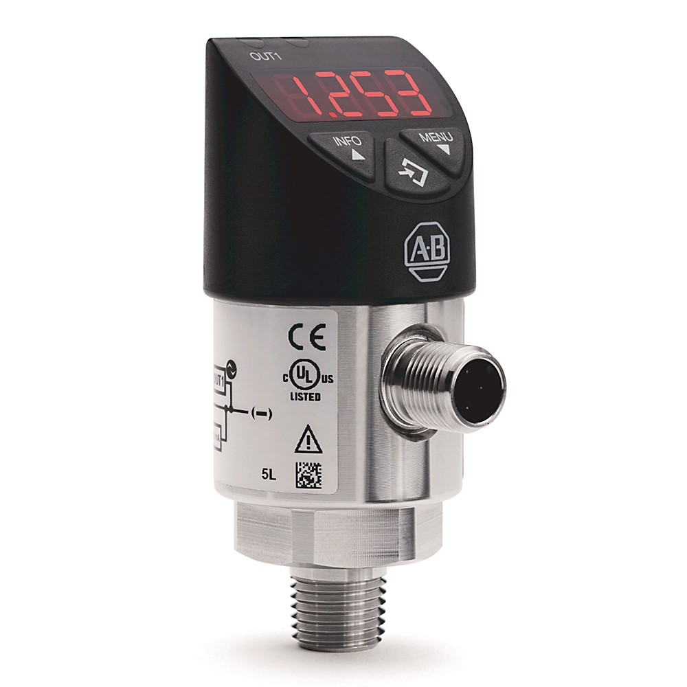
Standard Solid-State Pressure Sensor
| Unique Product Identifier |
836P-D2NFGC58PP-D4
|
|---|---|
| UPC |
887172994142
|
| Estimated Lead Time |
42 days
|
| Standard Warranty Duration |
1 year See details |
| Country of Origin |
Germany
|
| EU Importer Address |
Rockwell Automation N.V |
| EU Authorized Representative Address |
Rockwell Automation N.V |
The information provided by Rockwell Automation on www.rockwellautomation.com (the “Site”) is for demonstration purposes only and may be incomplete or inaccurate. All information is provided “as is”, and Rockwell Automation makes no representations or warranties of any kind, express or implied, regarding the accuracy, adequacy, validity, reliability, or completeness of any information on the Site. Use of this information is at your own risk.
| Model Type |
Standard
|
|---|
| With display |
True
|
|---|---|
| Readable |
True
|
| Housing material |
Stainless steel
|
| Position, nom |
Process connection lower mount (LM)
|
| Suitable for gases |
True
|
| Suitable for water |
True
|
| Suitable for steam |
True
|
| Suitable for air |
True
|
| Measuring element |
Piezo
|
| Sensor model |
Standard
|
| Connection type |
4 pin DC micro (M12)
|
| Display |
≤±1% of span ±1 digit
|
| Material |
Wetted parts: process connection: Stainless Steel 316 L, pressure sensing elements: <9.8 bar: Stainless Steel 316 L, ≥9.8 bar: Stainless Steel 13-8 PH, non-wetted parts: housing: Stainless steel 304, keyboard: TPE-E, display window: Polycarbonate, display
|
| Degree of protection (IP) |
IP67
|
|---|---|
| Width |
38 mm
|
| Depth |
48.5 mm
|
| Height |
92.3 mm
|
| Upper pressure range |
5800 psi
|
| Pressure type |
Gauge
|
| Thread size |
1/4 NPT female
|
| Service life |
100000000 switching cycles
|
| Shock |
50 G (1.76 oz) (IEC 60068-2-27, mechanical)
|
| Ingress rating |
IP65 and IP67. The stated ingress protection (per IEC 60529) only applies when plugged in with mating connectors that have the appropriate ingress protection
|
| Zero offset adjustment |
Maximum 3% of span
|
| Output signal |
Other
|
|---|---|
| Power supply |
15…35V DC
|
| Lower pressure range |
0 psi
|
| Reverse polarity protection |
V+ vs. V-
|
| Output type |
2xPNP IO-link
|
| Long term drift |
≤±0.2% of span (IEC 61298-2)
|
| Non-linearity |
≤±0.5% of span (BFSL, IEC 61298-2)
|
| Settling time |
Switching output : 20 ms with IO-link
|
| Current consumption |
With IO-Link: maximum 450 mA including switching current
|
| With temperature sensor |
False
|
| Cycle time, min |
3 ms
|
| Data storage support |
True
|
| Overvoltage protection |
40V DC
|
| Insulation voltage |
500V DC
|
| IO-link protocol |
Version 1.1
|
| Output voltage |
Power supply -1 V
|
| Rate |
COM2 (38.4 k Baud)
|
| Process data length |
16 bit (frame 2.2)
|
| Short circuit protection |
4...20 mA, Out 1/Out 2 vs. V-
|
| Output threshold |
OUT 1 and OUT 2 are individually adjustable
|
| Rated output current |
With IO-link : OUT1 maximum 100 mA, OUT2 maximum 250 mA
|
| Output mode |
Selectable - normally open, normally closed, window, hysteresis
|
| Switching output |
Switch point accuracy: ≤±1% of span, adjustment accuracy: ≤±0.5% of span
|
| Operating temperature |
15 °F
|
|---|---|
| Storage temperature |
-20 °F
|
| Atmospheric pressure |
950 mbar
|
| Ambient temperature |
-20 to 80 °C (-4 to 176 °F)
|
| Temperature error |
In rate temperature range: typical: ≤±1% of span, maximum: ≤±2.5% of span
|
| Media |
-20 °C
|
| Humidity |
45...75 % r. h.
|
| Vibration |
10 G (0.35 oz) (IEC 60068-2-6, under resonance)
|
| Overpressure limit |
2 times. 1.7 times for the relative pressure measuring ranges 16 psi, 1000 psi, and 1500 psi
|
| Temperature coefficient |
In rated temperature range: mean TC zero point: ≤±0.2% of span/10 K (typical), mean TC span: ≤±0.1% of span/10 K (typical)
|
| Drawings | |
|---|---|
| 3D STEP Model (STP) | Download (ZIP) |
| Product Drawing | Drawing (DWG) |
| Drawings |
|---|
| 3D STEP Model (STP) Download (ZIP) |
| Product Drawing Drawing (DWG) |
| General | Publication |
|---|---|
| Product Cutsheet | -- |
| Installation Instructions | Publication |
|---|---|
| 836p-in001_-en-p | 836P-IN001 |
- UKCA DOC
This product was certified with the above certifications as of {}. Products sold before or after this date might carry different certifications. Please review the product label to check for the certifications your specific product carries.
| Technotes |
|---|
Overview
| Unique Product Identifier |
836P-D2NFGC58PP-D4
|
|---|---|
| UPC |
887172994142
|
| Estimated Lead Time |
42 days
|
| Standard Warranty Duration |
1 year See details |
| Country of Origin |
Germany
|
| EU Importer Address |
Rockwell Automation N.V |
| EU Authorized Representative Address |
Rockwell Automation N.V |
The information provided by Rockwell Automation on www.rockwellautomation.com (the “Site”) is for demonstration purposes only and may be incomplete or inaccurate. All information is provided “as is”, and Rockwell Automation makes no representations or warranties of any kind, express or implied, regarding the accuracy, adequacy, validity, reliability, or completeness of any information on the Site. Use of this information is at your own risk.
Technical Specifications
| Model Type |
Standard
|
|---|
| With display |
True
|
|---|---|
| Readable |
True
|
| Housing material |
Stainless steel
|
| Position, nom |
Process connection lower mount (LM)
|
| Suitable for gases |
True
|
| Suitable for water |
True
|
| Suitable for steam |
True
|
| Suitable for air |
True
|
| Measuring element |
Piezo
|
| Sensor model |
Standard
|
| Connection type |
4 pin DC micro (M12)
|
| Display |
≤±1% of span ±1 digit
|
| Material |
Wetted parts: process connection: Stainless Steel 316 L, pressure sensing elements: <9.8 bar: Stainless Steel 316 L, ≥9.8 bar: Stainless Steel 13-8 PH, non-wetted parts: housing: Stainless steel 304, keyboard: TPE-E, display window: Polycarbonate, display
|
| Degree of protection (IP) |
IP67
|
|---|---|
| Width |
38 mm
|
| Depth |
48.5 mm
|
| Height |
92.3 mm
|
| Upper pressure range |
5800 psi
|
| Pressure type |
Gauge
|
| Thread size |
1/4 NPT female
|
| Service life |
100000000 switching cycles
|
| Shock |
50 G (1.76 oz) (IEC 60068-2-27, mechanical)
|
| Ingress rating |
IP65 and IP67. The stated ingress protection (per IEC 60529) only applies when plugged in with mating connectors that have the appropriate ingress protection
|
| Zero offset adjustment |
Maximum 3% of span
|
| Output signal |
Other
|
|---|---|
| Power supply |
15…35V DC
|
| Lower pressure range |
0 psi
|
| Reverse polarity protection |
V+ vs. V-
|
| Output type |
2xPNP IO-link
|
| Long term drift |
≤±0.2% of span (IEC 61298-2)
|
| Non-linearity |
≤±0.5% of span (BFSL, IEC 61298-2)
|
| Settling time |
Switching output : 20 ms with IO-link
|
| Current consumption |
With IO-Link: maximum 450 mA including switching current
|
| With temperature sensor |
False
|
| Cycle time, min |
3 ms
|
| Data storage support |
True
|
| Overvoltage protection |
40V DC
|
| Insulation voltage |
500V DC
|
| IO-link protocol |
Version 1.1
|
| Output voltage |
Power supply -1 V
|
| Rate |
COM2 (38.4 k Baud)
|
| Process data length |
16 bit (frame 2.2)
|
| Short circuit protection |
4...20 mA, Out 1/Out 2 vs. V-
|
| Output threshold |
OUT 1 and OUT 2 are individually adjustable
|
| Rated output current |
With IO-link : OUT1 maximum 100 mA, OUT2 maximum 250 mA
|
| Output mode |
Selectable - normally open, normally closed, window, hysteresis
|
| Switching output |
Switch point accuracy: ≤±1% of span, adjustment accuracy: ≤±0.5% of span
|
| Operating temperature |
15 °F
|
|---|---|
| Storage temperature |
-20 °F
|
| Atmospheric pressure |
950 mbar
|
| Ambient temperature |
-20 to 80 °C (-4 to 176 °F)
|
| Temperature error |
In rate temperature range: typical: ≤±1% of span, maximum: ≤±2.5% of span
|
| Media |
-20 °C
|
| Humidity |
45...75 % r. h.
|
| Vibration |
10 G (0.35 oz) (IEC 60068-2-6, under resonance)
|
| Overpressure limit |
2 times. 1.7 times for the relative pressure measuring ranges 16 psi, 1000 psi, and 1500 psi
|
| Temperature coefficient |
In rated temperature range: mean TC zero point: ≤±0.2% of span/10 K (typical), mean TC span: ≤±0.1% of span/10 K (typical)
|
Drawings
| Drawings | |
|---|---|
| 3D STEP Model (STP) | Download (ZIP) |
| Product Drawing | Drawing (DWG) |
| Drawings |
|---|
| 3D STEP Model (STP) Download (ZIP) |
| Product Drawing Drawing (DWG) |
Documents
|
Product Cutsheet
General
-- |
|
836p-in001_-en-p
Installation Instructions
836P-IN001 |
| General | Publication |
|---|---|
| Product Cutsheet | -- |
| Installation Instructions | Publication |
| 836p-in001_-en-p | 836P-IN001 |
Certifications
- UKCA DOC
This product was certified with the above certifications as of {}. Products sold before or after this date might carry different certifications. Please review the product label to check for the certifications your specific product carries.
Accessories
Alternative Products
Technotes
| Technotes |
|---|