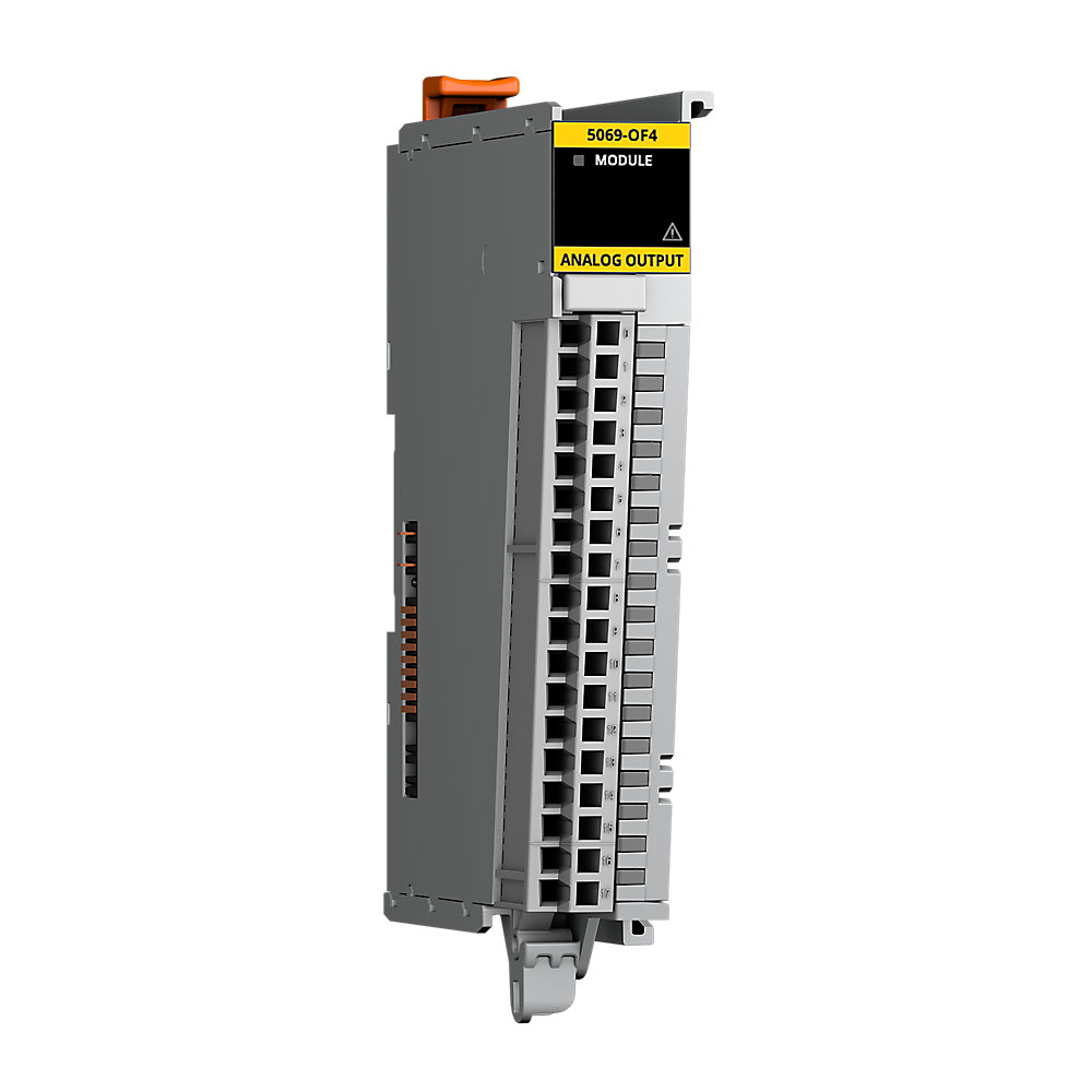

Compact 5000 Analog Output Module
| Unique Product Identifier |
5069-OF4
|
|---|---|
| UPC |
885630530093
|
| Estimated Lead Time |
5 days
|
| Standard Warranty Duration |
1 year See details |
| Country of Origin |
Malaysia
|
The information provided by Rockwell Automation on www.rockwellautomation.com (the “Site”) is for demonstration purposes only and may be incomplete or inaccurate. All information is provided “as is”, and Rockwell Automation makes no representations or warranties of any kind, express or implied, regarding the accuracy, adequacy, validity, reliability, or completeness of any information on the Site. Use of this information is at your own risk.
| Number Of Channels |
4 Channel
|
|---|---|
| Output Signal |
Analog
|
| Number of analogue outputs |
4
|
|---|---|
| Input, current |
False
|
| Input, voltage |
False
|
| Input, resistor |
False
|
| Input, resistance thermometer |
False
|
| Input, thermocouple |
False
|
| Output, current |
True
|
| Output, voltage |
True
|
| Analogue inputs configurable |
False
|
| Analogue outputs configurable |
True
|
| Type of electric connection |
Screw-/spring clA connection
|
| SA power |
150mA @ 18...32V DC
|
| SA power passthrough, max |
9.95A @ 18...32V DC
|
| Capacitive load, max |
1 µF (voltage mode only)
|
| Inductive load, max |
1 mH (current mode only)
|
| Module keying |
Electronic keying via progming software
|
| Scan time |
Per group 0...3: 1 ms
|
| Step response time to 63% of value |
Voltage mode: 18 µs max, Current mode: 1 ms max
|
| Module conversion method |
R-Ladder DAC, monotonicity with no missing codes
|
| Outputs |
4 voltage or current
|
| Open circuit detection |
Current mode only
|
| Drive capability |
Voltage: 1000 Ω minimum, Current: 500 Ω maximum
|
| RTB torque |
5069-RTB18-SCREW RTB only: 0.4 Nm (3.5 lbin)
|
| Overvoltage protection, max |
±32V DC
|
| Short circuit detection |
Voltage mode only - output electronically limited to 16 mA or less
|
| Data format |
IEEE 32-bit floating point
|
| Wire category |
2 - shielded input ports, 2 - power ports, 1 wire per terminal for each signal port
|
| Power dissipation, max |
3.3 W
|
| Indicators |
1 green/red module status indicator, 4 yellow/red I/O status indicators
|
| Thermal dissipation, max |
11.3 BTU/hr
|
| Accuracy drift with temperature |
Voltage: 0.30% full scale, Current: 0.50% full scale
|
| Isolation voltage |
250V (continuous), basic insulation type, 50V Functional isolation between SA power and input ports, No isolation between individual input ports
|
| Resolution |
16 bit across ±10.5V - 320 µV/bit, 16 bit across 10.5V - 160 µV/bit, 16 bit across 5.25V - 80 µV/bit, 16 bit across 21 mA - 320 nA/bit
|
| Wire size |
5069-RTB18-SPRING removable terminal block: 0.5...1.5 mm² (22...16 AWG) solid or stranded copper wire rated at 105 °C (221 °F), or greater, 2.9 mm (0.11 in.), max diam including insulation, 5069-RTB18-SCREW removable terminal block: 0.5...1.5 mm² (22.
|
| Calibrated accuracy |
Voltage: 0.10% full scale @ 25 °C Current: 0.10% full scale @ 25 °C
|
| Suitable for safety functions |
False
|
| Repeatability |
0.05 %
|
| Conversion time |
Per channel: 25 µs
|
| MOD power |
75mA @ 18...32V DC
|
| MOD power passthrough, max |
9.55A @ 18...32V DC
|
| Output range, current |
0...20mA @ 4...20mA
|
| Output range, voltage |
±10V @ 0...10V, 0...5V
|
| Analog output ratings |
±10V DC @ 0...20mA per channel
|
| Calibration methods |
Factory calibrated, User-performed (optional)
|
| Insulation stripping length |
5069-RTB18-SPRING connections: 10 mm (0.39 in.), 5069-RTB18-SCREW connections: 12 mm (0.47 in.)
|
| Surrounding air temperature, max |
60 °C
|
|---|---|
| North American temperature code |
T4
|
| Operating temperature |
0 °C
|
| Emissions |
IEC 61000-6-4
|
| ESD immunity |
6 kV contact discharges, 8 kV air discharges
|
| EFT/B immunity |
±4kV @ 5kHz on power ports, ±3kV @ 5kHz on shielded output ports
|
| Relative humidity |
5...95% noncondensing
|
| Conducted RF immunity |
10V rms with 1 kHz sine-wave 80% AM from 150 kHz...80 MHz
|
| Surge transient immunity |
±1 kV line-line (DM) and ±2 kV line-earth (CM) on power ports, ±2 kV line-earth (CM) on shielded output ports
|
| Radiated RF immunity |
10 V/m with 1 kHz sine-wave 80% AM from 80...2000 MHz, 10 V/m with 200 Hz 50% Pulse 100% AM @ 900 MHz, 10 V/m with 200 Hz 50% Pulse 100% AM @ 1890 MHz, 3 V/m with 1 kHz sine-wave 80% AM from 2000...2700 MHz
|
| Nonoperating temperature |
-40 °C
|
| Voltage variation |
10 ms interruption on MOD power port
|
| Width |
22 mm
|
|---|---|
| Height |
144.57 mm
|
| Depth |
105.42 mm
|
| Enclosure type |
None (open-style)
|
| RTB keying |
None
|
|---|---|
| Weight |
175 g
|
| Vibration |
5 G @ 10...500 Hz
|
| Shock |
Operating: 30 G, Non operating: 50 G
|
| Slot width |
1
|
| DIN rail |
Compatible zinc-plated chromate-passivated steel DIN rail, You can use the EN50022 - 35 x 7.5 mm (1.38 x 0.30 in)
|
| Drawings | |
|---|---|
| Dimensional Drawing in 3D (PDF) | Download (PDF) |
| 2-Dimensional Drawing (DWG/DXF) | Download (ZIP) |
| 3-Dimensional STEP model (STP) | Download (ZIP) |
| 2-Dimensional Drawing (PDF) | Download (PDF) |
| Drawings |
|---|
| Dimensional Drawing in 3D (PDF) Download (PDF) |
| 2-Dimensional Drawing (DWG/DXF) Download (ZIP) |
| 3-Dimensional STEP model (STP) Download (ZIP) |
| 2-Dimensional Drawing (PDF) Download (PDF) |
| General | Publication |
|---|---|
| User Manual | 5000-UM005 |
| Product Cutsheet | -- |
| Technical Data | Publication |
|---|---|
| 5069-td001_-en-p | 5069-TD001 |
- EDS files for CompactLogix Family (multi)
- EDS files for 5069-OF4/ 5069-OF4K (multi)
- Firmware for 5069-OF4/ 5069-OF4K v2.013
- AOP - Add On Profiles for Analog Modules v40.10
- China CCC
- American Bureau of Shippin
- Registro Italiano Navale
- UK EX CERTIFICATE
- MOROCCO DOC
- Eurasion Economic Community
This product was certified with the above certifications as of 2026-05-20. Products sold before or after this date might carry different certifications. Please review the product label to check for the certifications your specific product carries.
Looking for certification documents?
Explore certifications for this product and more in our comprehensive Literature Library.
| EU Importer Address |
Rockwell Automation N.V |
|---|---|
| EU Authorized Representative Address |
Rockwell Automation N.V |
| Technotes |
|---|
Overview
| Unique Product Identifier |
5069-OF4
|
|---|---|
| UPC |
885630530093
|
| Estimated Lead Time |
5 days
|
| Standard Warranty Duration |
1 year See details |
| Country of Origin |
Malaysia
|
The information provided by Rockwell Automation on www.rockwellautomation.com (the “Site”) is for demonstration purposes only and may be incomplete or inaccurate. All information is provided “as is”, and Rockwell Automation makes no representations or warranties of any kind, express or implied, regarding the accuracy, adequacy, validity, reliability, or completeness of any information on the Site. Use of this information is at your own risk.
Electrical & Connectivity
| Number Of Channels |
4 Channel
|
|---|---|
| Output Signal |
Analog
|
| Number of analogue outputs |
4
|
|---|---|
| Input, current |
False
|
| Input, voltage |
False
|
| Input, resistor |
False
|
| Input, resistance thermometer |
False
|
| Input, thermocouple |
False
|
| Output, current |
True
|
| Output, voltage |
True
|
| Analogue inputs configurable |
False
|
| Analogue outputs configurable |
True
|
| Type of electric connection |
Screw-/spring clA connection
|
| SA power |
150mA @ 18...32V DC
|
| SA power passthrough, max |
9.95A @ 18...32V DC
|
| Capacitive load, max |
1 µF (voltage mode only)
|
| Inductive load, max |
1 mH (current mode only)
|
| Module keying |
Electronic keying via progming software
|
| Scan time |
Per group 0...3: 1 ms
|
| Step response time to 63% of value |
Voltage mode: 18 µs max, Current mode: 1 ms max
|
| Module conversion method |
R-Ladder DAC, monotonicity with no missing codes
|
| Outputs |
4 voltage or current
|
| Open circuit detection |
Current mode only
|
| Drive capability |
Voltage: 1000 Ω minimum, Current: 500 Ω maximum
|
| RTB torque |
5069-RTB18-SCREW RTB only: 0.4 Nm (3.5 lbin)
|
| Overvoltage protection, max |
±32V DC
|
| Short circuit detection |
Voltage mode only - output electronically limited to 16 mA or less
|
| Data format |
IEEE 32-bit floating point
|
| Wire category |
2 - shielded input ports, 2 - power ports, 1 wire per terminal for each signal port
|
| Power dissipation, max |
3.3 W
|
| Indicators |
1 green/red module status indicator, 4 yellow/red I/O status indicators
|
| Thermal dissipation, max |
11.3 BTU/hr
|
| Accuracy drift with temperature |
Voltage: 0.30% full scale, Current: 0.50% full scale
|
| Isolation voltage |
250V (continuous), basic insulation type, 50V Functional isolation between SA power and input ports, No isolation between individual input ports
|
| Resolution |
16 bit across ±10.5V - 320 µV/bit, 16 bit across 10.5V - 160 µV/bit, 16 bit across 5.25V - 80 µV/bit, 16 bit across 21 mA - 320 nA/bit
|
| Wire size |
5069-RTB18-SPRING removable terminal block: 0.5...1.5 mm² (22...16 AWG) solid or stranded copper wire rated at 105 °C (221 °F), or greater, 2.9 mm (0.11 in.), max diam including insulation, 5069-RTB18-SCREW removable terminal block: 0.5...1.5 mm² (22.
|
| Calibrated accuracy |
Voltage: 0.10% full scale @ 25 °C Current: 0.10% full scale @ 25 °C
|
| Suitable for safety functions |
False
|
| Repeatability |
0.05 %
|
| Conversion time |
Per channel: 25 µs
|
| MOD power |
75mA @ 18...32V DC
|
| MOD power passthrough, max |
9.55A @ 18...32V DC
|
| Output range, current |
0...20mA @ 4...20mA
|
| Output range, voltage |
±10V @ 0...10V, 0...5V
|
| Analog output ratings |
±10V DC @ 0...20mA per channel
|
| Calibration methods |
Factory calibrated, User-performed (optional)
|
| Insulation stripping length |
5069-RTB18-SPRING connections: 10 mm (0.39 in.), 5069-RTB18-SCREW connections: 12 mm (0.47 in.)
|
Compliance & Environment
| Surrounding air temperature, max |
60 °C
|
|---|---|
| North American temperature code |
T4
|
| Operating temperature |
0 °C
|
| Emissions |
IEC 61000-6-4
|
| ESD immunity |
6 kV contact discharges, 8 kV air discharges
|
| EFT/B immunity |
±4kV @ 5kHz on power ports, ±3kV @ 5kHz on shielded output ports
|
| Relative humidity |
5...95% noncondensing
|
| Conducted RF immunity |
10V rms with 1 kHz sine-wave 80% AM from 150 kHz...80 MHz
|
| Surge transient immunity |
±1 kV line-line (DM) and ±2 kV line-earth (CM) on power ports, ±2 kV line-earth (CM) on shielded output ports
|
| Radiated RF immunity |
10 V/m with 1 kHz sine-wave 80% AM from 80...2000 MHz, 10 V/m with 200 Hz 50% Pulse 100% AM @ 900 MHz, 10 V/m with 200 Hz 50% Pulse 100% AM @ 1890 MHz, 3 V/m with 1 kHz sine-wave 80% AM from 2000...2700 MHz
|
| Nonoperating temperature |
-40 °C
|
| Voltage variation |
10 ms interruption on MOD power port
|
Physical Characteristics
| Width |
22 mm
|
|---|---|
| Height |
144.57 mm
|
| Depth |
105.42 mm
|
| Enclosure type |
None (open-style)
|
| RTB keying |
None
|
|---|---|
| Weight |
175 g
|
| Vibration |
5 G @ 10...500 Hz
|
| Shock |
Operating: 30 G, Non operating: 50 G
|
| Slot width |
1
|
| DIN rail |
Compatible zinc-plated chromate-passivated steel DIN rail, You can use the EN50022 - 35 x 7.5 mm (1.38 x 0.30 in)
|
Drawings
| Drawings | |
|---|---|
| Dimensional Drawing in 3D (PDF) | Download (PDF) |
| 2-Dimensional Drawing (DWG/DXF) | Download (ZIP) |
| 3-Dimensional STEP model (STP) | Download (ZIP) |
| 2-Dimensional Drawing (PDF) | Download (PDF) |
| Drawings |
|---|
| Dimensional Drawing in 3D (PDF) Download (PDF) |
| 2-Dimensional Drawing (DWG/DXF) Download (ZIP) |
| 3-Dimensional STEP model (STP) Download (ZIP) |
| 2-Dimensional Drawing (PDF) Download (PDF) |
Documents
|
User Manual
General
5000-UM005 |
|
Product Cutsheet
General
-- |
|
5069-td001_-en-p
Technical Data
5069-TD001 |
| General | Publication |
|---|---|
| User Manual | 5000-UM005 |
| Product Cutsheet | -- |
| Technical Data | Publication |
| 5069-td001_-en-p | 5069-TD001 |
Downloads
- EDS files for CompactLogix Family (multi)
- EDS files for 5069-OF4/ 5069-OF4K (multi)
- Firmware for 5069-OF4/ 5069-OF4K v2.013
- AOP - Add On Profiles for Analog Modules v40.10
Certifications
- China CCC
- American Bureau of Shippin
- Registro Italiano Navale
- UK EX CERTIFICATE
- MOROCCO DOC
- Eurasion Economic Community
This product was certified with the above certifications as of 2026-05-20. Products sold before or after this date might carry different certifications. Please review the product label to check for the certifications your specific product carries.
Looking for certification documents?
Explore certifications for this product and more in our comprehensive Literature Library.
| EU Importer Address |
Rockwell Automation N.V |
|---|---|
| EU Authorized Representative Address |
Rockwell Automation N.V |
Accessories
Technotes
| Technotes |
|---|