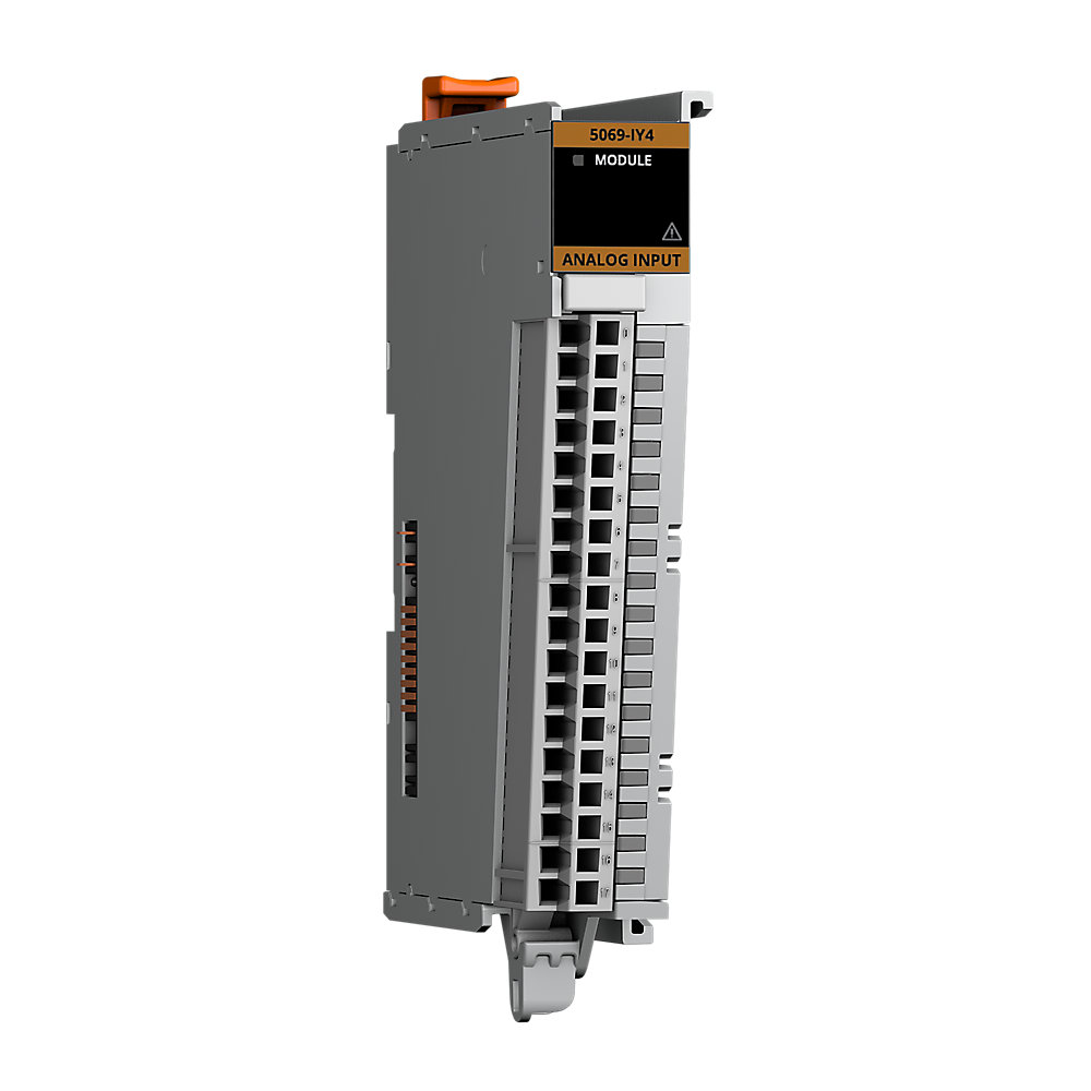

Compact 5000 UniversalAnalog InputModule
| Unique Product Identifier |
5069-IY4
|
|---|---|
| UPC |
885630530147
|
| Estimated Lead Time |
5 days
|
| Standard Warranty Duration |
1 year See details |
| Country of Origin |
Multiple
|
The information provided by Rockwell Automation on www.rockwellautomation.com (the “Site”) is for demonstration purposes only and may be incomplete or inaccurate. All information is provided “as is”, and Rockwell Automation makes no representations or warranties of any kind, express or implied, regarding the accuracy, adequacy, validity, reliability, or completeness of any information on the Site. Use of this information is at your own risk.
| Number Of Channels |
4 Channel
|
|---|---|
| Output Signal |
Analog
|
| Number of analogue inputs |
4
|
|---|---|
| Input, current |
True
|
| Input, voltage |
True
|
| Input, resistor |
True
|
| Input, resistance thermometer |
True
|
| Input, thermocouple |
True
|
| Output, current |
False
|
| Output, voltage |
False
|
| Analogue inputs configurable |
True
|
| Analogue outputs configurable |
False
|
| Type of electric connection |
Screw-/spring clA connection
|
| Local CJC sensor accuracy |
±0.3 °C
|
| SA power |
100mA @ 18...32V DC
|
| SA power passthrough, max |
9.95A @ 18...32V DC
|
| Input range, current |
0...20mA @ 4....20mA
|
| Remote CJC sensor accuracy |
Based on specified thermistor: ±0.3 °C
|
| RTD excitation current |
600 µA, 3 wire mode, 100 µA, 2 wire mode
|
| Module keying |
Electronic keying via progming software
|
| Scan time |
Per channel: 625 µs, Per group: 2.5 ms
|
| Step response time to 63% of value |
7.5 ms (Notch filter 10 kHz)
|
| Module conversion method |
Sigma-Delta, One 24-bit multiplexed ADC
|
| RTB torque |
5069-RTB18-SCREW, 5069-RTB14CJC-SCREW: 0.4 Nm (3.5 lbin)
|
| Overvoltage protection, max |
Voltage, current, RTD, and thermocouple/mV modes: ±30V DC
|
| Common mode voltage |
±10V (Current mode and 3-wire RTD mode), ±2V (Voltage mode)
|
| Data format |
IEEE 32-bit floating point
|
| Wire category |
2 - shielded input ports, 2 - power ports, 1 wire per terminal for each signal port
|
| Power dissipation, max |
Voltage mode: 1.8 W, Current mode: 2.1 W, RTD mode: 2.1 W, Thermocouple / mvolt mode: 1.8 W
|
| Indicators |
1 green/red module status indicator, 4 yellow/red I/O status indicators, 2 yellow/red CJC status indicators
|
| Thermal dissipation, max |
Voltage mode: 6.1 BTU/hr, Current mode: 7.2 BTU/hr, RTD mode: 7.2 BTU/hr, Thermocouple/mvolt: 6.1 BTU/hr
|
| Accuracy drift with temperature |
Voltage: 0.200% full scale, Current: 0.300% full scale, RTD: 0.200% full scale, Thermocouple/mvolt: 0.200% full scale
|
| Input Total Unadjusted Error (TUE) |
Voltage: 0.300% full Scale, Current: 0.400% full Scale, RTD: 0.300% full Scale, Thermocouple/mvolt: 0.300% full Scale
|
| Inputs |
4 differential
|
| Isolation voltage |
250V (continuous), basic insulation type, 50V Functional isolation between SA power and input ports, No isolation between individual input ports
|
| Wire size |
5069-RTB18-SPRING and 5069-RTB14CJCSPRING connections: 0.5...1.5 mm² (22...16 AWG) solid or stranded shielded copper wire rated at 105 °C (221 °F), or greater, 2.9 mm (0.11 in.), max diam including insulation, single wire connection only, 5069-RTB18-S
|
| Calibrated accuracy |
Voltage: 0.100% full scale @ 25 °C Current: 0.100% full scale @ 25 °C RTD: 0.100% full scale @ 25 °C Thermocouple/mvolt: 0.100% full scale @ 25 °C
|
| Suitable for safety functions |
False
|
| Notch filter frequency at RPI of 2.5 ms, min |
10 khz
|
| Input anti-aliasing filter cutoff frequency, typical |
500 Hz
|
| Onboard data alarming |
True
|
| Scaling to engineering units |
True
|
| Real-time channel sampling |
True
|
| Thermocouple linearization |
ITS-90
|
| Input range, thermocouple / millivolt |
±100 mV
|
| Common mode noise rejection ratio |
130 dB @ 50/60 Hz
|
| MOD power |
75mA @ 18...32V DC
|
| Overcurrent protection, max |
Current mode: ±30 mA
|
| MOD power passthrough, max |
9.55A @ 18...32V DC
|
| Input range, voltage |
±10V @ 0...10V, 0...5V
|
| Notch filter at minimum RPI |
62.5 kHz (0.2 ms, 1 channel enabled)
|
| Input type, thermocouple |
B, C, D, E, J, K, L (TXK/XK), N, R, S, T
|
| Normal mode noise rejection ratio |
65 dB @ 50/60 Hz, notch filter dependent
|
| Input digital filter |
First order lag, 0 ms…32,767 ms (32.767 s)
|
| Input range, resistive |
1...500 Ω, 2...1000 Ω, 4...2000 Ω, 8...4000 Ω
|
| Calibration methods |
Factory calibrated, User-performed (optional)
|
| Data value during overload condition |
Full scale, overrange flag, Data uncertain / data bad
|
| Resolution, thermocouple / millivolt |
16 bit at 10 Hz notch filter: <3.1 µV/cnt in ±100 mV mode
|
| Wire impedance |
25 Ω maximum for specified accuracy (3-wire RTD mode only)
|
| HART handheld compliance |
Add an external 250 Ω resistor into the current loop for HART transmitter compliance
|
| Insulation stripping length |
5069-RTB18-SPRING connections: 10 mm (0.39 in.), 5069-RTB18-SCREW connections: 12 mm (0.47 in.)
|
| Resolution, current |
16 bit at 10 Hz notch filter: 0...21 mA: <0.32 µA/count (16 bit), 3.6...21 mA: <0.27 µA/count (16 bit)
|
| Input notch filter (Hz) selections |
5, 10 (50/60 default), 15, 20, 50, 60, 100, 200, 500, 1000, 2500, 5000, 10000, 15625, 25000, 31250, 62500
|
| Open circuit detection time, nom |
Voltage: + full scale, <2 s, Current: 4...20 mA range, <2 s, RTD: <2 s, Thermocouple / mvolt: + full scale, <10 s
|
| Input type, RTD |
100, 200, 500, 1000 Ω platinum, alpha=385, 100, 200, 500, 1000 Ω platinum, alpha=3916, 120 Ω nickel, alpha=672, 100, 120, 200, 500 Ω nickel, alpha=618, 10 Ω copper 427
|
| Resolution, voltage |
16 bit at 10 Hz notch filter: ±10.5V: <320 µV/count (15 bit plus sign bipolar), 0...10.5V: <160 µV/count (16 bit unipolar), 0...5.25V: <80 µ/V count (16 bit unipolar)
|
| Resolution, RTD |
(16 bit at 10 Hz notch filter) 3 wire mode: <7.9 mΩ/cnt in 1...500 Ω mode, <15.8 mΩ/cnt in 2...1000 Ω mode, <31.7 mΩ/cnt in 4...2000 Ω mode, <63.4 mΩ/cnt in 8...4000 Ω mode
|
| CJC inputs |
Two CJC sensors, 2 thermistors embedded in 5069-RTB14CJC-(screw or spring) RTB, -or- 2 thermistors wired to 5069-RTB18-(screw or spring) RTB, Thermistor type: Measurement specialties, Inc. 10K3A1A, (for thermocouple mode use only)
|
| RTD sensor types/temperature range |
100, 200, 500, 1000 Ω PT 385: -200...870 °C, -328...1598 °F, 73...1143 °K, 132...2058 °R, 100, 200, 500, 1000 Ω PT 3916: -200...630 °C, -328...1166 °F, 73...903 °K, 132...1626 °R, 10 Ω CU 247: -200...260 °C, -328...500 °F, 73...533 °K, 132...960 °R,
|
| Thermocouple type/temperature range |
Thermocouple Type B: 21…1820 °C, 68…3308 °F, 293…2093 °K, 528…3768 °R, Thermocouple Type C: 0…2320 °C, 32…4208 °F, 273…2593 °K, 492…4668 °R, Thermocouple Type D: 0…2320 °C, 32…4208 °F, 273…2593 °K, 492…4668 °R, Thermocouple Type E: -270…1000 °C, -454…18
|
| Input impedance |
Voltage: >1 MΩ, Current: 90 Ω typical, 70…110 Ω range, RTD: >1 MΩ, Thermocouple/mvolt: >1 MΩ
|
|---|
| Surrounding air temperature, max |
60 °C
|
|---|---|
| North American temperature code |
T4
|
| Operating temperature |
0 °C
|
| Emissions |
IEC 61000-6-4
|
| ESD immunity |
6 kV contact discharges, 8 kV air discharges
|
| EFT/B immunity |
±4kV @ 5kHz on power ports, ±3kV @ 5kHz on shielded input ports
|
| Relative humidity |
5...95% noncondensing
|
| Conducted RF immunity |
10V rms with 1 kHz sine-wave 80% AM from 150 kHz...80 MHz
|
| Surge transient immunity |
±1 kV line-line (DM) and ±2 kV line-earth (CM) on power ports, ±2 kV line-earth (CM) on shielded input ports
|
| Radiated RF immunity |
10 V/m with 1 kHz sine-wave 80% AM from 80...2000 MHz, 10 V/m with 200 Hz 50% Pulse 100% AM @ 900 MHz, 10 V/m with 200 Hz 50% Pulse 100% AM @ 1890 MHz, 3 V/m with 1 kHz sine-wave 80% AM from 2000...2700 MHz
|
| Nonoperating temperature |
-40 °C
|
| Voltage variation |
10 ms interruption on MOD power port
|
| Width |
22 mm
|
|---|---|
| Height |
144.57 mm
|
| Depth |
105.42 mm
|
| Enclosure type |
None (open-style)
|
| RTB keying |
None
|
|---|---|
| Weight |
175 g
|
| Vibration |
5 G @ 10...500 Hz
|
| Shock |
Operating: 30 G, Non operating: 50 G
|
| Slot width |
1
|
| DIN rail |
Compatible zinc-plated chromate-passivated steel DIN rail, You can use the EN50022 - 35 x 7.5 mm (1.38 x 0.30 in)
|
| Drawings | |
|---|---|
| 3-Dimensional STEP model (STP) | Download (ZIP) |
| 2-Dimensional Drawing (DWG/DXF) | Download (ZIP) |
| 2-Dimensional Drawing (PDF) | Download (PDF) |
| Dimensional Drawing in 3D (PDF) | Download (PDF) |
| Drawings |
|---|
| 3-Dimensional STEP model (STP) Download (ZIP) |
| 2-Dimensional Drawing (DWG/DXF) Download (ZIP) |
| 2-Dimensional Drawing (PDF) Download (PDF) |
| Dimensional Drawing in 3D (PDF) Download (PDF) |
| General | Publication |
|---|---|
| Product Cutsheet | -- |
| User Manual | 5000-UM005 |
| Technical Data | Publication |
|---|---|
| 5069-td001_-en-p | 5069-TD001 |
- EDS files for CompactLogix Family (multi)
- EDS files for 5069-IY4/ 5069-IY4K (multi)
- Firmware for 5069-IY4/ 5069-IY4K v2.012
- AOP - Add On Profiles for Analog Modules v40.10
This product was certified with the above certifications as of 2026-05-19. Products sold before or after this date might carry different certifications. Please review the product label to check for the certifications your specific product carries.
Looking for certification documents?
Explore certifications for this product and more in our comprehensive Literature Library.
| EU Importer Address |
Rockwell Automation N.V |
|---|---|
| EU Authorized Representative Address |
Rockwell Automation N.V |
| Technotes |
|---|
Overview
| Unique Product Identifier |
5069-IY4
|
|---|---|
| UPC |
885630530147
|
| Estimated Lead Time |
5 days
|
| Standard Warranty Duration |
1 year See details |
| Country of Origin |
Multiple
|
The information provided by Rockwell Automation on www.rockwellautomation.com (the “Site”) is for demonstration purposes only and may be incomplete or inaccurate. All information is provided “as is”, and Rockwell Automation makes no representations or warranties of any kind, express or implied, regarding the accuracy, adequacy, validity, reliability, or completeness of any information on the Site. Use of this information is at your own risk.
Electrical & Connectivity
| Number Of Channels |
4 Channel
|
|---|---|
| Output Signal |
Analog
|
| Number of analogue inputs |
4
|
|---|---|
| Input, current |
True
|
| Input, voltage |
True
|
| Input, resistor |
True
|
| Input, resistance thermometer |
True
|
| Input, thermocouple |
True
|
| Output, current |
False
|
| Output, voltage |
False
|
| Analogue inputs configurable |
True
|
| Analogue outputs configurable |
False
|
| Type of electric connection |
Screw-/spring clA connection
|
| Local CJC sensor accuracy |
±0.3 °C
|
| SA power |
100mA @ 18...32V DC
|
| SA power passthrough, max |
9.95A @ 18...32V DC
|
| Input range, current |
0...20mA @ 4....20mA
|
| Remote CJC sensor accuracy |
Based on specified thermistor: ±0.3 °C
|
| RTD excitation current |
600 µA, 3 wire mode, 100 µA, 2 wire mode
|
| Module keying |
Electronic keying via progming software
|
| Scan time |
Per channel: 625 µs, Per group: 2.5 ms
|
| Step response time to 63% of value |
7.5 ms (Notch filter 10 kHz)
|
| Module conversion method |
Sigma-Delta, One 24-bit multiplexed ADC
|
| RTB torque |
5069-RTB18-SCREW, 5069-RTB14CJC-SCREW: 0.4 Nm (3.5 lbin)
|
| Overvoltage protection, max |
Voltage, current, RTD, and thermocouple/mV modes: ±30V DC
|
| Common mode voltage |
±10V (Current mode and 3-wire RTD mode), ±2V (Voltage mode)
|
| Data format |
IEEE 32-bit floating point
|
| Wire category |
2 - shielded input ports, 2 - power ports, 1 wire per terminal for each signal port
|
| Power dissipation, max |
Voltage mode: 1.8 W, Current mode: 2.1 W, RTD mode: 2.1 W, Thermocouple / mvolt mode: 1.8 W
|
| Indicators |
1 green/red module status indicator, 4 yellow/red I/O status indicators, 2 yellow/red CJC status indicators
|
| Thermal dissipation, max |
Voltage mode: 6.1 BTU/hr, Current mode: 7.2 BTU/hr, RTD mode: 7.2 BTU/hr, Thermocouple/mvolt: 6.1 BTU/hr
|
| Accuracy drift with temperature |
Voltage: 0.200% full scale, Current: 0.300% full scale, RTD: 0.200% full scale, Thermocouple/mvolt: 0.200% full scale
|
| Input Total Unadjusted Error (TUE) |
Voltage: 0.300% full Scale, Current: 0.400% full Scale, RTD: 0.300% full Scale, Thermocouple/mvolt: 0.300% full Scale
|
| Inputs |
4 differential
|
| Isolation voltage |
250V (continuous), basic insulation type, 50V Functional isolation between SA power and input ports, No isolation between individual input ports
|
| Wire size |
5069-RTB18-SPRING and 5069-RTB14CJCSPRING connections: 0.5...1.5 mm² (22...16 AWG) solid or stranded shielded copper wire rated at 105 °C (221 °F), or greater, 2.9 mm (0.11 in.), max diam including insulation, single wire connection only, 5069-RTB18-S
|
| Calibrated accuracy |
Voltage: 0.100% full scale @ 25 °C Current: 0.100% full scale @ 25 °C RTD: 0.100% full scale @ 25 °C Thermocouple/mvolt: 0.100% full scale @ 25 °C
|
| Suitable for safety functions |
False
|
| Notch filter frequency at RPI of 2.5 ms, min |
10 khz
|
| Input anti-aliasing filter cutoff frequency, typical |
500 Hz
|
| Onboard data alarming |
True
|
| Scaling to engineering units |
True
|
| Real-time channel sampling |
True
|
| Thermocouple linearization |
ITS-90
|
| Input range, thermocouple / millivolt |
±100 mV
|
| Common mode noise rejection ratio |
130 dB @ 50/60 Hz
|
| MOD power |
75mA @ 18...32V DC
|
| Overcurrent protection, max |
Current mode: ±30 mA
|
| MOD power passthrough, max |
9.55A @ 18...32V DC
|
| Input range, voltage |
±10V @ 0...10V, 0...5V
|
| Notch filter at minimum RPI |
62.5 kHz (0.2 ms, 1 channel enabled)
|
| Input type, thermocouple |
B, C, D, E, J, K, L (TXK/XK), N, R, S, T
|
| Normal mode noise rejection ratio |
65 dB @ 50/60 Hz, notch filter dependent
|
| Input digital filter |
First order lag, 0 ms…32,767 ms (32.767 s)
|
| Input range, resistive |
1...500 Ω, 2...1000 Ω, 4...2000 Ω, 8...4000 Ω
|
| Calibration methods |
Factory calibrated, User-performed (optional)
|
| Data value during overload condition |
Full scale, overrange flag, Data uncertain / data bad
|
| Resolution, thermocouple / millivolt |
16 bit at 10 Hz notch filter: <3.1 µV/cnt in ±100 mV mode
|
| Wire impedance |
25 Ω maximum for specified accuracy (3-wire RTD mode only)
|
| HART handheld compliance |
Add an external 250 Ω resistor into the current loop for HART transmitter compliance
|
| Insulation stripping length |
5069-RTB18-SPRING connections: 10 mm (0.39 in.), 5069-RTB18-SCREW connections: 12 mm (0.47 in.)
|
| Resolution, current |
16 bit at 10 Hz notch filter: 0...21 mA: <0.32 µA/count (16 bit), 3.6...21 mA: <0.27 µA/count (16 bit)
|
| Input notch filter (Hz) selections |
5, 10 (50/60 default), 15, 20, 50, 60, 100, 200, 500, 1000, 2500, 5000, 10000, 15625, 25000, 31250, 62500
|
| Open circuit detection time, nom |
Voltage: + full scale, <2 s, Current: 4...20 mA range, <2 s, RTD: <2 s, Thermocouple / mvolt: + full scale, <10 s
|
| Input type, RTD |
100, 200, 500, 1000 Ω platinum, alpha=385, 100, 200, 500, 1000 Ω platinum, alpha=3916, 120 Ω nickel, alpha=672, 100, 120, 200, 500 Ω nickel, alpha=618, 10 Ω copper 427
|
| Resolution, voltage |
16 bit at 10 Hz notch filter: ±10.5V: <320 µV/count (15 bit plus sign bipolar), 0...10.5V: <160 µV/count (16 bit unipolar), 0...5.25V: <80 µ/V count (16 bit unipolar)
|
| Resolution, RTD |
(16 bit at 10 Hz notch filter) 3 wire mode: <7.9 mΩ/cnt in 1...500 Ω mode, <15.8 mΩ/cnt in 2...1000 Ω mode, <31.7 mΩ/cnt in 4...2000 Ω mode, <63.4 mΩ/cnt in 8...4000 Ω mode
|
| CJC inputs |
Two CJC sensors, 2 thermistors embedded in 5069-RTB14CJC-(screw or spring) RTB, -or- 2 thermistors wired to 5069-RTB18-(screw or spring) RTB, Thermistor type: Measurement specialties, Inc. 10K3A1A, (for thermocouple mode use only)
|
| RTD sensor types/temperature range |
100, 200, 500, 1000 Ω PT 385: -200...870 °C, -328...1598 °F, 73...1143 °K, 132...2058 °R, 100, 200, 500, 1000 Ω PT 3916: -200...630 °C, -328...1166 °F, 73...903 °K, 132...1626 °R, 10 Ω CU 247: -200...260 °C, -328...500 °F, 73...533 °K, 132...960 °R,
|
| Thermocouple type/temperature range |
Thermocouple Type B: 21…1820 °C, 68…3308 °F, 293…2093 °K, 528…3768 °R, Thermocouple Type C: 0…2320 °C, 32…4208 °F, 273…2593 °K, 492…4668 °R, Thermocouple Type D: 0…2320 °C, 32…4208 °F, 273…2593 °K, 492…4668 °R, Thermocouple Type E: -270…1000 °C, -454…18
|
| Input impedance |
Voltage: >1 MΩ, Current: 90 Ω typical, 70…110 Ω range, RTD: >1 MΩ, Thermocouple/mvolt: >1 MΩ
|
|---|
Compliance & Environment
| Surrounding air temperature, max |
60 °C
|
|---|---|
| North American temperature code |
T4
|
| Operating temperature |
0 °C
|
| Emissions |
IEC 61000-6-4
|
| ESD immunity |
6 kV contact discharges, 8 kV air discharges
|
| EFT/B immunity |
±4kV @ 5kHz on power ports, ±3kV @ 5kHz on shielded input ports
|
| Relative humidity |
5...95% noncondensing
|
| Conducted RF immunity |
10V rms with 1 kHz sine-wave 80% AM from 150 kHz...80 MHz
|
| Surge transient immunity |
±1 kV line-line (DM) and ±2 kV line-earth (CM) on power ports, ±2 kV line-earth (CM) on shielded input ports
|
| Radiated RF immunity |
10 V/m with 1 kHz sine-wave 80% AM from 80...2000 MHz, 10 V/m with 200 Hz 50% Pulse 100% AM @ 900 MHz, 10 V/m with 200 Hz 50% Pulse 100% AM @ 1890 MHz, 3 V/m with 1 kHz sine-wave 80% AM from 2000...2700 MHz
|
| Nonoperating temperature |
-40 °C
|
| Voltage variation |
10 ms interruption on MOD power port
|
Physical Characteristics
| Width |
22 mm
|
|---|---|
| Height |
144.57 mm
|
| Depth |
105.42 mm
|
| Enclosure type |
None (open-style)
|
| RTB keying |
None
|
|---|---|
| Weight |
175 g
|
| Vibration |
5 G @ 10...500 Hz
|
| Shock |
Operating: 30 G, Non operating: 50 G
|
| Slot width |
1
|
| DIN rail |
Compatible zinc-plated chromate-passivated steel DIN rail, You can use the EN50022 - 35 x 7.5 mm (1.38 x 0.30 in)
|
Drawings
| Drawings | |
|---|---|
| 3-Dimensional STEP model (STP) | Download (ZIP) |
| 2-Dimensional Drawing (DWG/DXF) | Download (ZIP) |
| 2-Dimensional Drawing (PDF) | Download (PDF) |
| Dimensional Drawing in 3D (PDF) | Download (PDF) |
| Drawings |
|---|
| 3-Dimensional STEP model (STP) Download (ZIP) |
| 2-Dimensional Drawing (DWG/DXF) Download (ZIP) |
| 2-Dimensional Drawing (PDF) Download (PDF) |
| Dimensional Drawing in 3D (PDF) Download (PDF) |
Documents
|
Product Cutsheet
General
-- |
|
User Manual
General
5000-UM005 |
|
5069-td001_-en-p
Technical Data
5069-TD001 |
| General | Publication |
|---|---|
| Product Cutsheet | -- |
| User Manual | 5000-UM005 |
| Technical Data | Publication |
| 5069-td001_-en-p | 5069-TD001 |
Downloads
- EDS files for CompactLogix Family (multi)
- EDS files for 5069-IY4/ 5069-IY4K (multi)
- Firmware for 5069-IY4/ 5069-IY4K v2.012
- AOP - Add On Profiles for Analog Modules v40.10
Certifications
This product was certified with the above certifications as of 2026-05-19. Products sold before or after this date might carry different certifications. Please review the product label to check for the certifications your specific product carries.
Looking for certification documents?
Explore certifications for this product and more in our comprehensive Literature Library.
| EU Importer Address |
Rockwell Automation N.V |
|---|---|
| EU Authorized Representative Address |
Rockwell Automation N.V |
Accessories
Technotes
| Technotes |
|---|