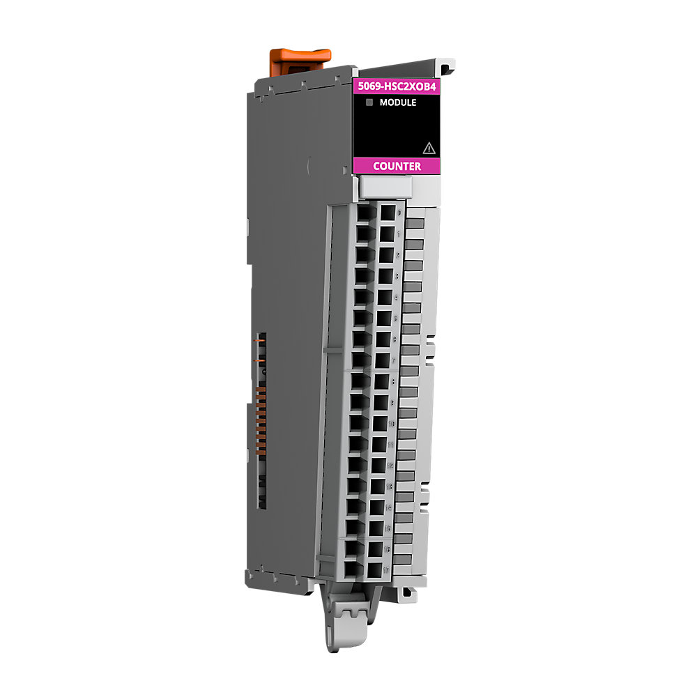

Compact 5000 High Speed Counter Module
| Unique Product Identifier |
5069-HSC2XOB4
|
|---|---|
| UPC |
885630530024
|
| Estimated Lead Time |
5 days
|
| Standard Warranty Duration |
1 year See details |
| Country of Origin |
Multiple
|
The information provided by Rockwell Automation on www.rockwellautomation.com (the “Site”) is for demonstration purposes only and may be incomplete or inaccurate. All information is provided “as is”, and Rockwell Automation makes no representations or warranties of any kind, express or implied, regarding the accuracy, adequacy, validity, reliability, or completeness of any information on the Site. Use of this information is at your own risk.
| Depth |
105mm, 4.15"
|
|---|---|
| Height |
145mm, 5.69"
|
| Isolation |
300V(cont);No isolation
|
| Number Of Channels |
6
|
| Type of voltage (input voltage) |
DC
|
|---|---|
| Type of output voltage |
DC
|
| Analogue input, current |
False
|
| Analogue input, voltage |
False
|
| Analogue output, current |
False
|
| Analogue output, voltage |
False
|
| Short-circuit protection, digital outputs available |
True
|
| Voltage type of supply voltage |
DC
|
| Type of digital output |
Transistor
|
| Insulation stripping length |
5069-RTB18-SPRING connections: 10 mm (0.39 in.)
|
| Suitable for safety functions |
False
|
| Time delay at signal exchange |
20 ms
|
| Analogue input, resistor |
False
|
| Analogue input, resistor temperature |
False
|
| Analogue input, thermocouple |
False
|
| Analogue input signal configurable |
False
|
| Analogue output signal configurable |
False
|
| Digital in-/outputs, configurable |
True
|
| Type of electric connection |
Screw-/spring clA connection
|
| Input current, max |
8 mA
|
| Power dissipation, max |
3 W
|
| Off-state current, max |
1 mA
|
| On-state current, min |
4 mA
|
| Off-state voltage, max |
1.5 V
|
| Pulse width, min |
125 ns
|
| Pulse separation, min |
100 ns
|
| Output short circuit/overload protection |
True
|
| Thermal dissipation, max |
10.2 btu/h
|
| Reverse voltage protection |
32V DC
|
| On-state voltage, nom |
24V DC
|
| On-state voltage drop, max |
<0.3V DC
|
| ON-state voltage |
3...32V DC
|
| Output voltage range |
10...32V DC
|
| Voltage category |
12/24V DC source
|
| SA power |
3A @ 18...32V DC
|
| Counter input ratings |
4mA @ 3...32V DC
|
| MOD power |
50mA @ 18...32V DC
|
| Overvoltage protection, max |
36V (fuse protected)
|
| MOD Power passthrough |
9.55A @ 18...32V DC
|
| SA Power passthrough |
9.95A @ 10...32V DC
|
| No load detection diagnostics |
Yes (per channel diagnostics)
|
| Output short circuit/overload/overtemp detection |
Yes (per channel diagnostics)
|
| On-state output current, min |
1 mA per channel 4 mA per module
|
| Output control in fault state per point |
Hold last state, On, Off (default)
|
| Output states in program mode per point |
Hold last state, On, Off (default)
|
| Output states in fault mode per point |
Hold last state, On, Off (default)
|
| Outputs |
4 Channels (1 group of 4), sourcing
|
| Inputs |
2 quadrature (ABZ) differential inputs
|
| Duration of fault mode per point |
1 s, 2 s, 5 s, 10 s, Forever (default)
|
| Module keying |
Electronic keying via progming software
|
| Pilot duty |
Yes (make current electronically limited/protected @ 3.6 A)
|
| Indicators |
1 green/red module status indicator, 10 yellow/red I/O status indicator
|
| Wiring category |
2 - on shielded output ports, 2 - on output power ports, 2 - on shielded counter ports
|
| Isolation voltage |
250V (continuous), basic insulation type, No isolation between SA power and I/O ports, No isolation between individual I/O ports, Type tested at 1500V AC @ 60s
|
| Wire size |
5069-RTB18-SPRING connections: 0.5...1.5 mm² (22...16 AWG) solid or stranded shielded copper wire rated at 105 °C (221 °F), or greater, 2.9 mm (0.11 in.), maximum diam including insulation 5069-RTB18-SCREW connections: 0.5…1.5 mm² (22 AWG) solid or
|
| Surrounding air temperature, max |
60 °C
|
|---|---|
| Operating temperature |
0 °C
|
| Nonoperating temperature |
-40 °C
|
| Emissions |
IEC 61000-6-4
|
| Relative humidity |
5...95% noncondensing
|
| Voltage variation |
10 ms interruption on MOD Power port
|
| ESD immunity |
6 kV contact discharges, 8 kV air discharges
|
| Conducted RF immunity |
10Vrms with 1 kHz sine-wave 80% AM from 150 kHz...80 MHz
|
| EFT/B immunity |
±4kV @ 5kHz on power ports, ±2kV @ 5kHz on shielded output ports, ±2kV @ 5kHz on shielded counter ports
|
| Surge transient immunity |
±1 kV line-line (DM) and ±2 kV line-earth (CM) on power ports, ±2 kV line-earth (CM) on shielded output ports, ±2 kV line-earth (CM) on shielded counter ports
|
| Radiated RF immunity |
10 V/m with 1 kHz sine-wave 80% AM from 80...2000 MHz, 10 V/m with 200 Hz 50% Pulse 100% AM @ 900 MHz, 10 V/m with 200 Hz 50% Pulse 100% AM @ 1890 MHz, 3 V/m with 1 kHz sine-wave 80% AM from 2000...2700 MHz
|
| Width |
22 mm
|
|---|---|
| Height |
144.57 mm
|
| Depth |
105.42 mm
|
| Enclosure type |
None (open-style)
|
| Slot width |
1
|
|---|---|
| Weight, approx |
175 g
|
| RTB keying |
None
|
| Vibration |
5 G @ 10...500 Hz
|
| Shock |
Operating: 30 G, Non operating: 50 G
|
| RTB torque |
5069-RTB18-SCREW RTB only: 0.4 Nm (3.5 lbin)
|
| DIN rail |
Compatible zinc-plated chromate-passivated steel
|
| Environmental Compliance | |
|---|---|
| SVHC Information |
| Drawings | |
|---|---|
| 2-Dimensional Drawing (PDF) | Download (PDF) |
| 3-Dimensional STEP model (STP) | Download (ZIP) |
| Dimensional Drawing in 3D (PDF) | Download (PDF) |
| Product Drawing | Drawing (DWG) |
| Product Drawing | Drawing (DXF) |
| Drawings |
|---|
| 2-Dimensional Drawing (PDF) Download (PDF) |
| 3-Dimensional STEP model (STP) Download (ZIP) |
| Dimensional Drawing in 3D (PDF) Download (PDF) |
| Product Drawing Drawing (DWG) |
| Product Drawing Drawing (DXF) |
| General | Publication |
|---|---|
| Technical Detail | 5069-TD001 |
| User Manual | 5069-UM006 |
| Product Cutsheet | -- |
- China CCC
- Australian RCM
- ATEX
- IECEx Scheme
- Registro Italiano Navale
- UL Listed
- Eurasion Economic Community
This product was certified with the above certifications as of 2026-05-17. Products sold before or after this date might carry different certifications. Please review the product label to check for the certifications your specific product carries.
Looking for certification documents?
Explore certifications for this product and more in our comprehensive Literature Library.
| EU Importer Address |
Rockwell Automation N.V |
|---|---|
| EU Authorized Representative Address |
Rockwell Automation N.V |
| Technotes |
|---|
Overview
| Unique Product Identifier |
5069-HSC2XOB4
|
|---|---|
| UPC |
885630530024
|
| Estimated Lead Time |
5 days
|
| Standard Warranty Duration |
1 year See details |
| Country of Origin |
Multiple
|
The information provided by Rockwell Automation on www.rockwellautomation.com (the “Site”) is for demonstration purposes only and may be incomplete or inaccurate. All information is provided “as is”, and Rockwell Automation makes no representations or warranties of any kind, express or implied, regarding the accuracy, adequacy, validity, reliability, or completeness of any information on the Site. Use of this information is at your own risk.
Electrical & Connectivity
| Depth |
105mm, 4.15"
|
|---|---|
| Height |
145mm, 5.69"
|
| Isolation |
300V(cont);No isolation
|
| Number Of Channels |
6
|
| Type of voltage (input voltage) |
DC
|
|---|---|
| Type of output voltage |
DC
|
| Analogue input, current |
False
|
| Analogue input, voltage |
False
|
| Analogue output, current |
False
|
| Analogue output, voltage |
False
|
| Short-circuit protection, digital outputs available |
True
|
| Voltage type of supply voltage |
DC
|
| Type of digital output |
Transistor
|
| Insulation stripping length |
5069-RTB18-SPRING connections: 10 mm (0.39 in.)
|
| Suitable for safety functions |
False
|
| Time delay at signal exchange |
20 ms
|
| Analogue input, resistor |
False
|
| Analogue input, resistor temperature |
False
|
| Analogue input, thermocouple |
False
|
| Analogue input signal configurable |
False
|
| Analogue output signal configurable |
False
|
| Digital in-/outputs, configurable |
True
|
| Type of electric connection |
Screw-/spring clA connection
|
| Input current, max |
8 mA
|
| Power dissipation, max |
3 W
|
| Off-state current, max |
1 mA
|
| On-state current, min |
4 mA
|
| Off-state voltage, max |
1.5 V
|
| Pulse width, min |
125 ns
|
| Pulse separation, min |
100 ns
|
| Output short circuit/overload protection |
True
|
| Thermal dissipation, max |
10.2 btu/h
|
| Reverse voltage protection |
32V DC
|
| On-state voltage, nom |
24V DC
|
| On-state voltage drop, max |
<0.3V DC
|
| ON-state voltage |
3...32V DC
|
| Output voltage range |
10...32V DC
|
| Voltage category |
12/24V DC source
|
| SA power |
3A @ 18...32V DC
|
| Counter input ratings |
4mA @ 3...32V DC
|
| MOD power |
50mA @ 18...32V DC
|
| Overvoltage protection, max |
36V (fuse protected)
|
| MOD Power passthrough |
9.55A @ 18...32V DC
|
| SA Power passthrough |
9.95A @ 10...32V DC
|
| No load detection diagnostics |
Yes (per channel diagnostics)
|
| Output short circuit/overload/overtemp detection |
Yes (per channel diagnostics)
|
| On-state output current, min |
1 mA per channel 4 mA per module
|
| Output control in fault state per point |
Hold last state, On, Off (default)
|
| Output states in program mode per point |
Hold last state, On, Off (default)
|
| Output states in fault mode per point |
Hold last state, On, Off (default)
|
| Outputs |
4 Channels (1 group of 4), sourcing
|
| Inputs |
2 quadrature (ABZ) differential inputs
|
| Duration of fault mode per point |
1 s, 2 s, 5 s, 10 s, Forever (default)
|
| Module keying |
Electronic keying via progming software
|
| Pilot duty |
Yes (make current electronically limited/protected @ 3.6 A)
|
| Indicators |
1 green/red module status indicator, 10 yellow/red I/O status indicator
|
| Wiring category |
2 - on shielded output ports, 2 - on output power ports, 2 - on shielded counter ports
|
| Isolation voltage |
250V (continuous), basic insulation type, No isolation between SA power and I/O ports, No isolation between individual I/O ports, Type tested at 1500V AC @ 60s
|
| Wire size |
5069-RTB18-SPRING connections: 0.5...1.5 mm² (22...16 AWG) solid or stranded shielded copper wire rated at 105 °C (221 °F), or greater, 2.9 mm (0.11 in.), maximum diam including insulation 5069-RTB18-SCREW connections: 0.5…1.5 mm² (22 AWG) solid or
|
Compliance & Environment
| Surrounding air temperature, max |
60 °C
|
|---|---|
| Operating temperature |
0 °C
|
| Nonoperating temperature |
-40 °C
|
| Emissions |
IEC 61000-6-4
|
| Relative humidity |
5...95% noncondensing
|
| Voltage variation |
10 ms interruption on MOD Power port
|
| ESD immunity |
6 kV contact discharges, 8 kV air discharges
|
| Conducted RF immunity |
10Vrms with 1 kHz sine-wave 80% AM from 150 kHz...80 MHz
|
| EFT/B immunity |
±4kV @ 5kHz on power ports, ±2kV @ 5kHz on shielded output ports, ±2kV @ 5kHz on shielded counter ports
|
| Surge transient immunity |
±1 kV line-line (DM) and ±2 kV line-earth (CM) on power ports, ±2 kV line-earth (CM) on shielded output ports, ±2 kV line-earth (CM) on shielded counter ports
|
| Radiated RF immunity |
10 V/m with 1 kHz sine-wave 80% AM from 80...2000 MHz, 10 V/m with 200 Hz 50% Pulse 100% AM @ 900 MHz, 10 V/m with 200 Hz 50% Pulse 100% AM @ 1890 MHz, 3 V/m with 1 kHz sine-wave 80% AM from 2000...2700 MHz
|
Physical Characteristics
| Width |
22 mm
|
|---|---|
| Height |
144.57 mm
|
| Depth |
105.42 mm
|
| Enclosure type |
None (open-style)
|
| Slot width |
1
|
|---|---|
| Weight, approx |
175 g
|
| RTB keying |
None
|
| Vibration |
5 G @ 10...500 Hz
|
| Shock |
Operating: 30 G, Non operating: 50 G
|
| RTB torque |
5069-RTB18-SCREW RTB only: 0.4 Nm (3.5 lbin)
|
| DIN rail |
Compatible zinc-plated chromate-passivated steel
|
Drawings
| Drawings | |
|---|---|
| 2-Dimensional Drawing (PDF) | Download (PDF) |
| 3-Dimensional STEP model (STP) | Download (ZIP) |
| Dimensional Drawing in 3D (PDF) | Download (PDF) |
| Product Drawing | Drawing (DWG) |
| Product Drawing | Drawing (DXF) |
| Drawings |
|---|
| 2-Dimensional Drawing (PDF) Download (PDF) |
| 3-Dimensional STEP model (STP) Download (ZIP) |
| Dimensional Drawing in 3D (PDF) Download (PDF) |
| Product Drawing Drawing (DWG) |
| Product Drawing Drawing (DXF) |
Documents
|
Technical Detail
General
5069-TD001 |
|
User Manual
General
5069-UM006 |
|
Product Cutsheet
General
-- |
| General | Publication |
|---|---|
| Technical Detail | 5069-TD001 |
| User Manual | 5069-UM006 |
| Product Cutsheet | -- |
Certifications
- China CCC
- Australian RCM
- ATEX
- IECEx Scheme
- Registro Italiano Navale
- UL Listed
- Eurasion Economic Community
This product was certified with the above certifications as of 2026-05-17. Products sold before or after this date might carry different certifications. Please review the product label to check for the certifications your specific product carries.
Looking for certification documents?
Explore certifications for this product and more in our comprehensive Literature Library.
| EU Importer Address |
Rockwell Automation N.V |
|---|---|
| EU Authorized Representative Address |
Rockwell Automation N.V |
Accessories
Technotes
| Technotes |
|---|