
Compact 5000 EtherNet/IP Adapter
Compact 5000 EtherNet/IP Adapter
| Unique Product Identifier |
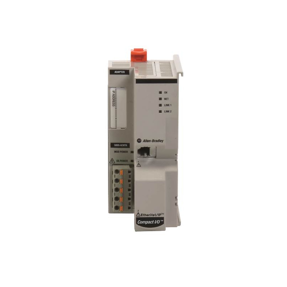
5069-AENTR
|
|---|---|
| UPC |
885630529943
|
| Estimated Lead Time |
73 days
|
| Standard Warranty Duration |
1 year See details |
| Country of Origin |
Multiple
|
| Depth |
105mm, 4.15"
|
|---|---|
| Height |
138mm, 5.43"
|
| Isolation |
300V(cont);No isolation
|
| ATEX temp code |
T4
|
|---|---|
| Enclosure type rating |
None (open-style)
|
| IO link master |
False
|
| Insulation stripping length |
5069-RTB5-SPRING connections: 10 mm (0.39 in.), 5069-RTB5-SCREW connections: 10 mm (0.39 in.)
|
| Isolation voltage |
250V (continuous), basic insulation type, SA, and MOD power to backplane, 250V (continuous), basic insulation type, SA to MOD power, 250V (continuous), basic insulation type, Ethernet to backplane, type tested at 1500V AC @ 60s, 250V (continuous), doub
|
| MOD Power inrush |
1750 mA for 70 ms
|
| MOD power |
220mA @ 18...32V DC
|
| MOD power passthrough, max |
9.78A @ 18...32V DC, Maximum level of MOD Power current that the adapter can pass through to the next module in the system
|
| Module keying |
Electronic keying via progming software
|
| Number of HW-interfaces industrial Ethernet |
1
|
| Power dissipation, max |
8.5 W
|
| RTB keying |
None
|
| RTB torque |
0.5...0.6 Nm (4.4...5.3 in-lb), (5069-RTB5-SCREW RTB only)
|
| Recommended external overcurrent protection |
MOD power: 10...12A @ 22.5...43.2A2t, fast acting, SA power: 20A @ 250V AC
|
| Redundancy |
False
|
| SA power |
5mA @ 0...32V DC, 2mA @ 0...240V AC, 47...63 Hz, ATEX/IECEx, 125V AC maximum
|
| SA power passthrough, max |
9.95A @ 0...32V DC, 9.975A @ 0...240V AC, 47...63 Hz, ATEX/IECEx, 125V AC maximum, Maximum level of SA power current that the adapter can pass through to the next module in the system
|
| Supporting protocol for AS-Interface Safety at Work |
False
|
| Supporting protocol for ASI |
False
|
| Supporting protocol for CAN |
False
|
| Supporting protocol for Data-Highway |
False
|
| Supporting protocol for DeviceNet |
False
|
| Supporting protocol for DeviceNet Safety |
False
|
| Supporting protocol for EtherNet/IP |
True
|
| Supporting protocol for Foundation Fieldbus |
False
|
| Supporting protocol for INTERBUS |
False
|
| Supporting protocol for INTERBUS-Safety |
False
|
| Supporting protocol for KNX |
False
|
| Supporting protocol for LON |
False
|
| Supporting protocol for Modbus |
False
|
| Supporting protocol for PROFIBUS |
False
|
| Supporting protocol for PROFINET CBA |
False
|
| Supporting protocol for PROFINET IO |
False
|
| Supporting protocol for PROFIsafe |
False
|
| Supporting protocol for SERCOS |
False
|
| Supporting protocol for SUCONET |
False
|
| Supporting protocol for SafetyBUS p |
False
|
| Supporting protocol for TCP/IP |
False
|
| Supporting protocol for other bus systems |
False
|
| Thermal dissipation, max |
29 btu/h
|
| Type of data transmission |
Module rack extension
|
| Wire size |
0.25...2.5 mm2 (22...14 AWG) solid or stranded copper wire rated at 105 °C (221 °F), or greater, 1.2 mm (3/64 in.), insulation m, single wire connection only, Grounding: 2.5 mm2 AWG) solid or stranded copper wire rated at 105 °C (221 °F), or greater,
|
| Wiring category |
2 - on signal ports, 1 - on power ports, 2 - on Ethernet ports
|
| With optical interface |
False
|
| With potential separation |
False
|
| Conducted RF immunity |
10V rms with 1 kHz sine-wave 80% AM from 150 kHz...80 MHz on power and Ethernet ports
|
|---|---|
| EFT/B immunity |
±3kV @ 5kHz on power ports, ±3kV @ 5kHz on Ethernet ports
|
| ESD immunity |
6 kV contact discharges, 8 kV air discharges
|
| Emissions |
CISPR 11/22, Class A
|
| Nonoperating temperature |
-40 °C
|
| Operating temperature |
0 °C <60 °C (32 °F <140 °F)
|
| Radiated RF immunity |
10V/m with 1 kHz sine-wave 80% AM from 80...2000 MHz, 10V/m with 200 Hz 50% Pulse 100% AM at 900 MHz, 10V/m with 200 Hz 50% Pulse 100% AM at 1890 MHz, 10V/m with 1 kHz sine-wave 80% AM from 2000...2700 MHz
|
| Relative humidity |
5...95% noncondensing
|
| Shock |
Operating: 30 G, Non operating: 50 G
|
| Surge transient immunity |
±1kV line-line (DM) and ±2kV line-earth (CM) on power ports, ±2kV line-earth (CM) on Ethernet ports
|
| Surrounding air temperature, max |
60 °C
|
| Vibration |
5 G @ 10...500 Hz
|
| Depth |
105 mm
|
|---|---|
| Height |
138 mm
|
| Width |
56 mm
|
| Environmental Compliance | |
|---|---|
| SVHC Information |
| Drawings | |
|---|---|
| 3-Dimensional STEP model (STP) | Download (ZIP) |
| 2-Dimensional Drawing (PDF) | Download (PDF) |
| Product Drawing | Drawing (DXF) |
| Drawings |
|---|
| 3-Dimensional STEP model (STP) Download (ZIP) |
| 2-Dimensional Drawing (PDF) Download (PDF) |
| Product Drawing Drawing (DXF) |
| General | Publication |
|---|---|
| Product Cutsheet | -- |
| User Manual | ENET-UM004 |
| Technical Data | Publication |
|---|---|
| 5069-td001_-en-p | 5069-TD001 |
- EDS files for 5069-AENTR/ 5069-AENTRK (multi)
- EDS files for CompactLogix Family (multi)
- Firmware for 5069-AENTR / 5069-AENTRK v4.012
- AOP - Add On Profiles for 5069-AENTR/ 5069-AENTRK v40.10.13
- China CCC
- Australian RCM
- Registro Italiano Navale
- UL Listed
- UL Listed Hazardous
- ATEX
- CE
- IECEx Scheme
- Korean KC
- American Bureau of Shippin
- ODVA
- UKCA DOC
- MOROCCO DOC
- UK EX CERTIFICATE
- Eurasion Economic Community
This product was certified with the above certifications as of 2026-07-14. Products sold before or after this date might carry different certifications. Please review the product label to check for the certifications your specific product carries.
Looking for certification documents?
Explore certifications for this product and more in our comprehensive Literature Library.
| EU Importer Address |
Rockwell Automation N.V |
|---|---|
| EU Authorized Representative Address |
Rockwell Automation N.V |
| Technotes |
|---|
Overview
| Unique Product Identifier |
5069-AENTR
|
|---|---|
| UPC |
885630529943
|
| Estimated Lead Time |
73 days
|
| Standard Warranty Duration |
1 year See details |
| Country of Origin |
Multiple
|
Electrical & Connectivity
| Depth |
105mm, 4.15"
|
|---|---|
| Height |
138mm, 5.43"
|
| Isolation |
300V(cont);No isolation
|
| ATEX temp code |
T4
|
|---|---|
| Enclosure type rating |
None (open-style)
|
| IO link master |
False
|
| Insulation stripping length |
5069-RTB5-SPRING connections: 10 mm (0.39 in.), 5069-RTB5-SCREW connections: 10 mm (0.39 in.)
|
| Isolation voltage |
250V (continuous), basic insulation type, SA, and MOD power to backplane, 250V (continuous), basic insulation type, SA to MOD power, 250V (continuous), basic insulation type, Ethernet to backplane, type tested at 1500V AC @ 60s, 250V (continuous), doub
|
| MOD Power inrush |
1750 mA for 70 ms
|
| MOD power |
220mA @ 18...32V DC
|
| MOD power passthrough, max |
9.78A @ 18...32V DC, Maximum level of MOD Power current that the adapter can pass through to the next module in the system
|
| Module keying |
Electronic keying via progming software
|
| Number of HW-interfaces industrial Ethernet |
1
|
| Power dissipation, max |
8.5 W
|
| RTB keying |
None
|
| RTB torque |
0.5...0.6 Nm (4.4...5.3 in-lb), (5069-RTB5-SCREW RTB only)
|
| Recommended external overcurrent protection |
MOD power: 10...12A @ 22.5...43.2A2t, fast acting, SA power: 20A @ 250V AC
|
| Redundancy |
False
|
| SA power |
5mA @ 0...32V DC, 2mA @ 0...240V AC, 47...63 Hz, ATEX/IECEx, 125V AC maximum
|
| SA power passthrough, max |
9.95A @ 0...32V DC, 9.975A @ 0...240V AC, 47...63 Hz, ATEX/IECEx, 125V AC maximum, Maximum level of SA power current that the adapter can pass through to the next module in the system
|
| Supporting protocol for AS-Interface Safety at Work |
False
|
| Supporting protocol for ASI |
False
|
| Supporting protocol for CAN |
False
|
| Supporting protocol for Data-Highway |
False
|
| Supporting protocol for DeviceNet |
False
|
| Supporting protocol for DeviceNet Safety |
False
|
| Supporting protocol for EtherNet/IP |
True
|
| Supporting protocol for Foundation Fieldbus |
False
|
| Supporting protocol for INTERBUS |
False
|
| Supporting protocol for INTERBUS-Safety |
False
|
| Supporting protocol for KNX |
False
|
| Supporting protocol for LON |
False
|
| Supporting protocol for Modbus |
False
|
| Supporting protocol for PROFIBUS |
False
|
| Supporting protocol for PROFINET CBA |
False
|
| Supporting protocol for PROFINET IO |
False
|
| Supporting protocol for PROFIsafe |
False
|
| Supporting protocol for SERCOS |
False
|
| Supporting protocol for SUCONET |
False
|
| Supporting protocol for SafetyBUS p |
False
|
| Supporting protocol for TCP/IP |
False
|
| Supporting protocol for other bus systems |
False
|
| Thermal dissipation, max |
29 btu/h
|
| Type of data transmission |
Module rack extension
|
| Wire size |
0.25...2.5 mm2 (22...14 AWG) solid or stranded copper wire rated at 105 °C (221 °F), or greater, 1.2 mm (3/64 in.), insulation m, single wire connection only, Grounding: 2.5 mm2 AWG) solid or stranded copper wire rated at 105 °C (221 °F), or greater,
|
| Wiring category |
2 - on signal ports, 1 - on power ports, 2 - on Ethernet ports
|
| With optical interface |
False
|
| With potential separation |
False
|
Compliance & Environment
| Conducted RF immunity |
10V rms with 1 kHz sine-wave 80% AM from 150 kHz...80 MHz on power and Ethernet ports
|
|---|---|
| EFT/B immunity |
±3kV @ 5kHz on power ports, ±3kV @ 5kHz on Ethernet ports
|
| ESD immunity |
6 kV contact discharges, 8 kV air discharges
|
| Emissions |
CISPR 11/22, Class A
|
| Nonoperating temperature |
-40 °C
|
| Operating temperature |
0 °C <60 °C (32 °F <140 °F)
|
| Radiated RF immunity |
10V/m with 1 kHz sine-wave 80% AM from 80...2000 MHz, 10V/m with 200 Hz 50% Pulse 100% AM at 900 MHz, 10V/m with 200 Hz 50% Pulse 100% AM at 1890 MHz, 10V/m with 1 kHz sine-wave 80% AM from 2000...2700 MHz
|
| Relative humidity |
5...95% noncondensing
|
| Shock |
Operating: 30 G, Non operating: 50 G
|
| Surge transient immunity |
±1kV line-line (DM) and ±2kV line-earth (CM) on power ports, ±2kV line-earth (CM) on Ethernet ports
|
| Surrounding air temperature, max |
60 °C
|
| Vibration |
5 G @ 10...500 Hz
|
Physical Characteristics
| Depth |
105 mm
|
|---|---|
| Height |
138 mm
|
| Width |
56 mm
|
Drawings
| Drawings | |
|---|---|
| 3-Dimensional STEP model (STP) | Download (ZIP) |
| 2-Dimensional Drawing (PDF) | Download (PDF) |
| Product Drawing | Drawing (DXF) |
| Drawings |
|---|
| 3-Dimensional STEP model (STP) Download (ZIP) |
| 2-Dimensional Drawing (PDF) Download (PDF) |
| Product Drawing Drawing (DXF) |
Documents
|
Product Cutsheet
General
-- |
|
User Manual
General
ENET-UM004 |
|
5069-td001_-en-p
Technical Data
5069-TD001 |
| General | Publication |
|---|---|
| Product Cutsheet | -- |
| User Manual | ENET-UM004 |
| Technical Data | Publication |
| 5069-td001_-en-p | 5069-TD001 |
Downloads
- EDS files for 5069-AENTR/ 5069-AENTRK (multi)
- EDS files for CompactLogix Family (multi)
- Firmware for 5069-AENTR / 5069-AENTRK v4.012
- AOP - Add On Profiles for 5069-AENTR/ 5069-AENTRK v40.10.13
Certifications
- China CCC
- Australian RCM
- Registro Italiano Navale
- UL Listed
- UL Listed Hazardous
- ATEX
- CE
- IECEx Scheme
- Korean KC
- American Bureau of Shippin
- ODVA
- UKCA DOC
- MOROCCO DOC
- UK EX CERTIFICATE
- Eurasion Economic Community
This product was certified with the above certifications as of 2026-07-14. Products sold before or after this date might carry different certifications. Please review the product label to check for the certifications your specific product carries.
Looking for certification documents?
Explore certifications for this product and more in our comprehensive Literature Library.
| EU Importer Address |
Rockwell Automation N.V |
|---|---|
| EU Authorized Representative Address |
Rockwell Automation N.V |
Accessories
Alternative Products
Technotes
| Technotes |
|---|