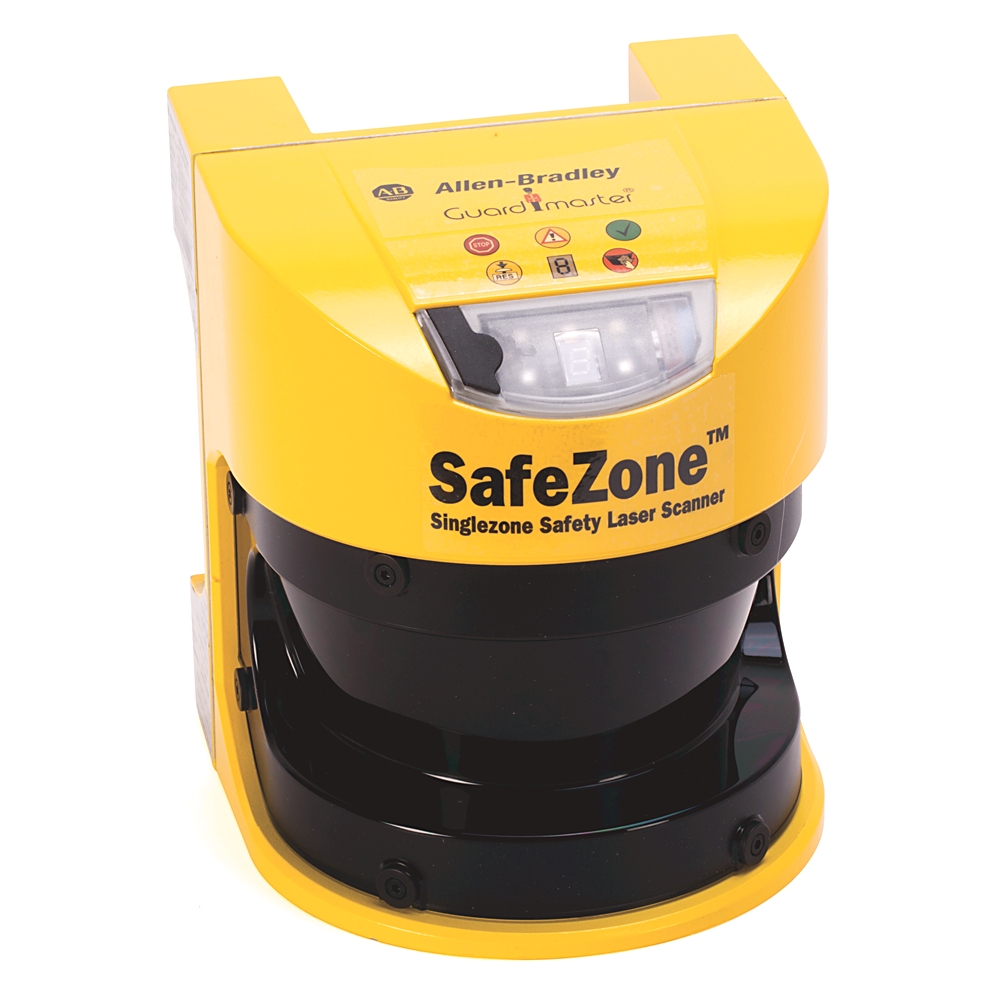
442L-SFZNMZ
SafeZone Safety Laser Scanner
Serial #:
This product has not been verified. Please {} to confirm authenticity.
register your product
Lifecycle status:
Discontinued
Rockwell Automation announces that as of September 28, 2026, the SafeZone Safety Laser Scanner will be discontinued and no longer available for sale. Customers are encouraged to remove references to the affected product(s)
Discontinued Date:
September 28, 2026
Replacement Category:
Engineering Replacement
Product at a glance
Description
SafeZone Multizone scan head and I/O module
442L-SFZNMZ
SafeZone Safety Laser Scanner
Serial #:
This product has not been verified. Please {} to confirm authenticity.
register your product
Lifecycle status:
Discontinued
Rockwell Automation announces that as of September 28, 2026, the SafeZone Safety Laser Scanner will be discontinued and no longer available for sale. Customers are encouraged to remove references to the affected product(s)
Discontinued Date:
September 28, 2026
Replacement Category:
Engineering Replacement
Product at a glance
Description
SafeZone Multizone scan head and I/O module
Overview
Electrical & Connectivity
Power & Electrical Characteristics
Communication & Interfaces
Relays & Control Outputs
Inputs & Outputs (I/O)
Wiring, Terminals & Physical Connections
Physical Characteristics
Construction
Mechanical
Compliance & Environment
Standards & Protection
Drawings
Documents
Downloads
Accessories
Alternative Products
Technotes
| Unique Product Identifier |
442L-SFZNMZ
|
|---|---|
| UPC |
662074015078
|
| Standard Warranty Duration |
1 year See details |
| Country of Origin |
Germany
|
| Angular resolution |
0.5 °
|
|---|---|
| Cable cross-section of the connecting cable |
0.25
|
| Cable length for power supply tolerance ±1% |
70 m maximum for cable cross-section 1 mm²
|
| Cable length for power supply tolerance ±10% |
50 m maximum for cable cross-section 1 mm²
|
| Cable length for power supply tolerance ±5% |
60 m maximum for cable cross-section 1 mm²
|
| Characteristic impedance of the connecting cable |
80 Ω...115 Ω (100 Ω typical)
|
| Current limiting |
600...920 mA (after 5 ms at 25 °C) (Application diagnostic outputs warning field, contamination of the front screen/error, reset necessary)
|
| Differential input threshold at the receiver |
±0.2V min. (between RxD+ and RxD-)
|
| Differential output voltage at the sender |
±2...±5V (between TxD+ and TxD-), with 50 ~ load
|
| Distance between centre of the scan plane and the bottom edge of the housing |
63 mm
|
| Distance from mirror axis of rotation (zero point on the X and Y axis) to the rear of the device |
93 mm
|
| Distance measuring range |
49 m
|
| Divergence of the collimated beam |
2.5 m radb
|
| Evenness of the scan field |
±70 mm maximum @ 5.0 m
|
| Galvanic de-coupling |
True
|
| Laser protection class |
Class 1
|
| Load capacity |
2.2 µF maximum @ 50 Ω
|
| Load inductance |
2.2 H maximum (the maximum rated load inductance is higher with lower switching sequence)
|
| Measurement error |
Systematic error: ±5 mm (Measured data error output up to 5.0 m, 1.8% reflectivity)
|
| Number of multiple samplings |
2...16 (configurable via SCD)
|
| Number of protected semiconductor outputs |
2
|
| Operating current, max |
2.3 A (with maximum output load)
|
| Output power, max |
562 µw
|
| PFD - probability of failure on demand |
4.46E-3 (minimum requirement = 1E-2)
|
| Part number |
Safezone multizone safety laser scanner head
|
| Permissible cable resistance |
2.5 Ω maximum (make sure to limit the individual line core resistance to the downstream controller to this value to ensure that a short-circuit between the outputs is safely detected (also note EN 60 204-1))
|
| Permissible residual ripple |
±5% maximum (The absolute voltage level must not drop below the specified minimum voltage)
|
| Power consumption, max |
55 W (with maximum output load)
|
| Power up delay |
1.4 ms typical...2 ms maximum (Application diagnostic outputs warning field, contamination of the front screen/error, reset necessary)
|
| Power up time |
9 s typical
|
| Protective safety field of the sensor head |
5.00 m maximum @ 70 mm resolution, 120 ms response time, with 5.0 m scanning range
|
| Protective safety field supplement generally necessary |
100 mm maximum
|
| Pulse duration, max |
3.1 ns
|
| Rated control supply voltage at DC |
24 V
|
| Reflectivity |
0.018
|
| Resolution |
30, 40, 50, 70, 150 mm
|
| Restart (after configurable) |
2 s
|
| Sender |
Pulsed laser diode
|
| Short-circuit current |
-60...60 mA @ TxD
|
| Size of light spot |
27 mm @ 5.0 m scanning range
|
| Suitable for safety functions |
True
|
| Supplement for retroreflectors in scan plane at a distance of less than 1 m to the protective safety field boundary |
200 mm maximum
|
| Supply voltage (SELV) |
16.8...28.8V (24V typical), The voltage supply must be capable of buffering brief mains voltage failures of 20 ms as specified in EN 60 204.
|
| Switch OFF delay |
0.7 ms typical...2 ms maximum
|
| Switch on current |
2 A maximum (The load currents for the input capacitors are not taken into account)
|
| Switching sequence |
Depending on load inductance (without switching and without simultaneous monitoring)
|
| Switching time of the OSSDs from red to green |
120
|
| System connector |
ESD protected
|
| Terminating resistance |
115 Ω...125 Ω (120 Ω typical)
|
| Test frequency |
120 ms
|
| Test pulse width |
230 µs typical...300 µs maximum (when active, the outputs are tested cyclically (brief LOW). When selecting the downstream controllers, make sure that the test pulses do not result in deactivation)
|
| Time offset on switching the OSSDs between OSSD2 and OSSD1 |
1.3 ms typical...2 ms maximum
|
| Type of connecting cable |
Twisted pairs with copper braid screen
|
| Type of electric connection |
Screw connection
|
| Type of switching output of the OSSD |
PNP
|
| Voltage level, max |
-29...29V @ TxD+, TxD
|
| Voltage type |
DC
|
| Warning field |
Approx. 20 m typical (For objects with 20% reflectivity.)
|
| With alert field output |
True
|
| With configurable message output |
True
|
| With restart blockage |
True
|
| Cable length |
15 m maximum @ 9600 baud, and 0.25 mm˄2 cables
|
|---|---|
| Communication protocol |
RS-422 (proprietary)
|
| Output TxD HIGH |
5 V
|
| Output TxD LOW |
-15 V
|
| Switching threshold RxD HIGH |
2.4 V
|
| Switching threshold RxD LOW |
-15 V
|
| Transmission speed |
9600 baud, 19200 baud, 38400 baud
|
| Transmission speed (selectable) |
19200 baud, 38400 baud, 125 kbaud, 250 kbaud, 500 kbaud
|
| Voltage range RxD |
-15
|
| HIGH switching voltage |
Uv-3.3V...Uv @ 200 mA (Application diagnostic outputs warning field, contamination of the front screen/error, reset necessary)
|
|---|---|
| Leakage current |
250 µA maximum (in the case of a fault (the 0V cable is open circuit) the leakage current flows through the OSSD cable as a maximum. The downstream controller must detect this status as LOW. An FPLC (fail-safe progmable logic controller) must detect th
|
| Output signal switching device pair |
2 PNP semiconductors, short-circuit protected (applies to the voltage range between Uv and 0V), cross-circuit monitored
|
| Source switching current |
6 mA...0.5 A (0.2 A typical)
|
| Switching voltage LOW |
0...3.5V (0V typical)
|
Input Signals
| Input capacitance |
15 nf
|
|---|---|
| Input frequency (maximum switching sequence or frequency) |
1/(multiple sAling + 1) x scan time x 2
|
| Input resistance when HIGH |
2 kohm
|
| Static input current |
6 mA
|
| Voltage for HIGH |
11...28.8V (24V typical)
|
| Voltage for LOW |
-3...5V (0V typical)
|
| American wire gauge (AWG) |
26...16
|
|---|---|
| Cross-section of flexible cores |
0.14...1.0 mm˄2 (core terminating sleeves are not required)
|
| Cross-section of rigid cores |
0.14
|
| Insulation stripping length for the cores |
5 mm
|
| Screw tightening torque |
0.22 nm
|
Construction
| Front screen material |
Polycarbonate
|
|---|---|
| Front screen surface finish |
Outside with scratch-resistant coating
|
| Functional safety programmable electronic system |
SIL 2, IEC/EN 61508
|
| Housing color |
RAL 1021
|
| Housing material |
Aluminium die-cast
|
| Protection class |
II (according to DIN VDE 0106, DIN EN 50178)
|
| Scan angle |
190 °
|
| Type of safety according to IEC 61496-1 |
3
|
Mechanical
| Depth |
160 mm
|
|---|---|
| Enclosure type rating |
IP65 (EN 60529)
|
| Height of sensor |
185 mm
|
| Shock |
Single shock: 15 G, 11 ms according to EN 60068-2-27, 10 G, 16 ms according to IEC/EN 61496-1, section 5.1.2 and 5.4.4.2, as well as IEC 61496-3, section 5.4.4.2
|
| Vibration |
Frequency range: 10...150 Hz (IEC/EN 61496-1, section 5.1.2 and 5.4.4.1, as well as IEC 61496-3, section 5.4.4.2)
|
| Wavelength of the sensor |
905 nm
|
| Weight |
3.3 kg
|
| Width sensor |
155 mm
|
| Humidity |
IEC/EN 61496-1, section 5.1.2 and 5.4.2, as well as IEC 61496-3, section 5.4.2 (taking into account the operating temperature range)
|
|---|---|
| Operating temperature |
-10 °C
|
| Storage temperature |
-25 °C
|
| Drawings | |
|---|---|
| 3-Dimensional STEP model (STP) | Download (ZIP) |
| 2-Dimensional Drawing (PDF) | Download (PDF) |
| 3D Dimensional Drawing | Download (ZIP) |
| Product Drawing | Drawing (DWG) |
| Drawings |
|---|
| 3-Dimensional STEP model (STP) Download (ZIP) |
| 2-Dimensional Drawing (PDF) Download (PDF) |
| 3D Dimensional Drawing Download (ZIP) |
| Product Drawing Drawing (DWG) |
| General | Publication |
|---|---|
| Product Overview | -- |
| Product Cutsheet | -- |
| User Manual | -- |
| User Manual | Publication |
|---|---|
| 442l-um003_-en-p | 442L-UM003 |
Looking for more documentation?
Find curated technical documentation for this product in the Technical Documentation Center, or search our full Literature Library.
Search the Literature Library
Version:
Release notes
| AOP - Add On Profiles | Size | Notes | |
|---|---|---|---|
|
|
AOP - Add On Profiles for SafeZone 3 CIP Safety Laser Scanner v2.01 | 538 MB | Release notes |
|
|
AOP - Add On Profiles for SafeZone 3 CIP Safety Laser Scanner v2.0 | 404 MB | Release notes |
| Accessory Files | Size | Notes | |
|
|
SafeZone Safety Laser Scanners Software v3.02.05 | 57.54 MB | |
AOP - Add On Profiles for SafeZone 3 CIP Safety Laser Scanner v2.01
AOP - Add On Profiles
538 MB
Release notes
AOP - Add On Profiles for SafeZone 3 CIP Safety Laser Scanner v2.0
AOP - Add On Profiles
404 MB
Release notes
Looking for more Downloads?
Find product downloads in Rockwell Automation Product Compatibility and Download Center.
Search PCDC
Items Per Page:
Items Per Page:
| Technotes |
|---|
Looking for more Technotes?
Find questions and answers from Rockwell Automation technical experts for this product in our Knowledgebase.
Search Knowledgebase
Overview
| Unique Product Identifier |
442L-SFZNMZ
|
|---|---|
| UPC |
662074015078
|
| Standard Warranty Duration |
1 year See details |
| Country of Origin |
Germany
|
Electrical & Connectivity
| Angular resolution |
0.5 °
|
|---|---|
| Cable cross-section of the connecting cable |
0.25
|
| Cable length for power supply tolerance ±1% |
70 m maximum for cable cross-section 1 mm²
|
| Cable length for power supply tolerance ±10% |
50 m maximum for cable cross-section 1 mm²
|
| Cable length for power supply tolerance ±5% |
60 m maximum for cable cross-section 1 mm²
|
| Characteristic impedance of the connecting cable |
80 Ω...115 Ω (100 Ω typical)
|
| Current limiting |
600...920 mA (after 5 ms at 25 °C) (Application diagnostic outputs warning field, contamination of the front screen/error, reset necessary)
|
| Differential input threshold at the receiver |
±0.2V min. (between RxD+ and RxD-)
|
| Differential output voltage at the sender |
±2...±5V (between TxD+ and TxD-), with 50 ~ load
|
| Distance between centre of the scan plane and the bottom edge of the housing |
63 mm
|
| Distance from mirror axis of rotation (zero point on the X and Y axis) to the rear of the device |
93 mm
|
| Distance measuring range |
49 m
|
| Divergence of the collimated beam |
2.5 m radb
|
| Evenness of the scan field |
±70 mm maximum @ 5.0 m
|
| Galvanic de-coupling |
True
|
| Laser protection class |
Class 1
|
| Load capacity |
2.2 µF maximum @ 50 Ω
|
| Load inductance |
2.2 H maximum (the maximum rated load inductance is higher with lower switching sequence)
|
| Measurement error |
Systematic error: ±5 mm (Measured data error output up to 5.0 m, 1.8% reflectivity)
|
| Number of multiple samplings |
2...16 (configurable via SCD)
|
| Number of protected semiconductor outputs |
2
|
| Operating current, max |
2.3 A (with maximum output load)
|
| Output power, max |
562 µw
|
| PFD - probability of failure on demand |
4.46E-3 (minimum requirement = 1E-2)
|
| Part number |
Safezone multizone safety laser scanner head
|
| Permissible cable resistance |
2.5 Ω maximum (make sure to limit the individual line core resistance to the downstream controller to this value to ensure that a short-circuit between the outputs is safely detected (also note EN 60 204-1))
|
| Permissible residual ripple |
±5% maximum (The absolute voltage level must not drop below the specified minimum voltage)
|
| Power consumption, max |
55 W (with maximum output load)
|
| Power up delay |
1.4 ms typical...2 ms maximum (Application diagnostic outputs warning field, contamination of the front screen/error, reset necessary)
|
| Power up time |
9 s typical
|
| Protective safety field of the sensor head |
5.00 m maximum @ 70 mm resolution, 120 ms response time, with 5.0 m scanning range
|
| Protective safety field supplement generally necessary |
100 mm maximum
|
| Pulse duration, max |
3.1 ns
|
| Rated control supply voltage at DC |
24 V
|
| Reflectivity |
0.018
|
| Resolution |
30, 40, 50, 70, 150 mm
|
| Restart (after configurable) |
2 s
|
| Sender |
Pulsed laser diode
|
| Short-circuit current |
-60...60 mA @ TxD
|
| Size of light spot |
27 mm @ 5.0 m scanning range
|
| Suitable for safety functions |
True
|
| Supplement for retroreflectors in scan plane at a distance of less than 1 m to the protective safety field boundary |
200 mm maximum
|
| Supply voltage (SELV) |
16.8...28.8V (24V typical), The voltage supply must be capable of buffering brief mains voltage failures of 20 ms as specified in EN 60 204.
|
| Switch OFF delay |
0.7 ms typical...2 ms maximum
|
| Switch on current |
2 A maximum (The load currents for the input capacitors are not taken into account)
|
| Switching sequence |
Depending on load inductance (without switching and without simultaneous monitoring)
|
| Switching time of the OSSDs from red to green |
120
|
| System connector |
ESD protected
|
| Terminating resistance |
115 Ω...125 Ω (120 Ω typical)
|
| Test frequency |
120 ms
|
| Test pulse width |
230 µs typical...300 µs maximum (when active, the outputs are tested cyclically (brief LOW). When selecting the downstream controllers, make sure that the test pulses do not result in deactivation)
|
| Time offset on switching the OSSDs between OSSD2 and OSSD1 |
1.3 ms typical...2 ms maximum
|
| Type of connecting cable |
Twisted pairs with copper braid screen
|
| Type of electric connection |
Screw connection
|
| Type of switching output of the OSSD |
PNP
|
| Voltage level, max |
-29...29V @ TxD+, TxD
|
| Voltage type |
DC
|
| Warning field |
Approx. 20 m typical (For objects with 20% reflectivity.)
|
| With alert field output |
True
|
| With configurable message output |
True
|
| With restart blockage |
True
|
| Cable length |
15 m maximum @ 9600 baud, and 0.25 mm˄2 cables
|
|---|---|
| Communication protocol |
RS-422 (proprietary)
|
| Output TxD HIGH |
5 V
|
| Output TxD LOW |
-15 V
|
| Switching threshold RxD HIGH |
2.4 V
|
| Switching threshold RxD LOW |
-15 V
|
| Transmission speed |
9600 baud, 19200 baud, 38400 baud
|
| Transmission speed (selectable) |
19200 baud, 38400 baud, 125 kbaud, 250 kbaud, 500 kbaud
|
| Voltage range RxD |
-15
|
| HIGH switching voltage |
Uv-3.3V...Uv @ 200 mA (Application diagnostic outputs warning field, contamination of the front screen/error, reset necessary)
|
|---|---|
| Leakage current |
250 µA maximum (in the case of a fault (the 0V cable is open circuit) the leakage current flows through the OSSD cable as a maximum. The downstream controller must detect this status as LOW. An FPLC (fail-safe progmable logic controller) must detect th
|
| Output signal switching device pair |
2 PNP semiconductors, short-circuit protected (applies to the voltage range between Uv and 0V), cross-circuit monitored
|
| Source switching current |
6 mA...0.5 A (0.2 A typical)
|
| Switching voltage LOW |
0...3.5V (0V typical)
|
Input Signals
| Input capacitance |
15 nf
|
|---|---|
| Input frequency (maximum switching sequence or frequency) |
1/(multiple sAling + 1) x scan time x 2
|
| Input resistance when HIGH |
2 kohm
|
| Static input current |
6 mA
|
| Voltage for HIGH |
11...28.8V (24V typical)
|
| Voltage for LOW |
-3...5V (0V typical)
|
| American wire gauge (AWG) |
26...16
|
|---|---|
| Cross-section of flexible cores |
0.14...1.0 mm˄2 (core terminating sleeves are not required)
|
| Cross-section of rigid cores |
0.14
|
| Insulation stripping length for the cores |
5 mm
|
| Screw tightening torque |
0.22 nm
|
Physical Characteristics
Construction
| Front screen material |
Polycarbonate
|
|---|---|
| Front screen surface finish |
Outside with scratch-resistant coating
|
| Functional safety programmable electronic system |
SIL 2, IEC/EN 61508
|
| Housing color |
RAL 1021
|
| Housing material |
Aluminium die-cast
|
| Protection class |
II (according to DIN VDE 0106, DIN EN 50178)
|
| Scan angle |
190 °
|
| Type of safety according to IEC 61496-1 |
3
|
Mechanical
| Depth |
160 mm
|
|---|---|
| Enclosure type rating |
IP65 (EN 60529)
|
| Height of sensor |
185 mm
|
| Shock |
Single shock: 15 G, 11 ms according to EN 60068-2-27, 10 G, 16 ms according to IEC/EN 61496-1, section 5.1.2 and 5.4.4.2, as well as IEC 61496-3, section 5.4.4.2
|
| Vibration |
Frequency range: 10...150 Hz (IEC/EN 61496-1, section 5.1.2 and 5.4.4.1, as well as IEC 61496-3, section 5.4.4.2)
|
| Wavelength of the sensor |
905 nm
|
| Weight |
3.3 kg
|
| Width sensor |
155 mm
|
Compliance & Environment
| Humidity |
IEC/EN 61496-1, section 5.1.2 and 5.4.2, as well as IEC 61496-3, section 5.4.2 (taking into account the operating temperature range)
|
|---|---|
| Operating temperature |
-10 °C
|
| Storage temperature |
-25 °C
|
Drawings
| Drawings | |
|---|---|
| 3-Dimensional STEP model (STP) | Download (ZIP) |
| 2-Dimensional Drawing (PDF) | Download (PDF) |
| 3D Dimensional Drawing | Download (ZIP) |
| Product Drawing | Drawing (DWG) |
| Drawings |
|---|
| 3-Dimensional STEP model (STP) Download (ZIP) |
| 2-Dimensional Drawing (PDF) Download (PDF) |
| 3D Dimensional Drawing Download (ZIP) |
| Product Drawing Drawing (DWG) |
Documents
|
Product Overview
General
-- |
|
Product Cutsheet
General
-- |
|
User Manual
General
-- |
|
442l-um003_-en-p
User Manual
442L-UM003 |
| General | Publication |
|---|---|
| Product Overview | -- |
| Product Cutsheet | -- |
| User Manual | -- |
| User Manual | Publication |
| 442l-um003_-en-p | 442L-UM003 |
Looking for more documentation?
Find curated technical documentation for this product in the Technical Documentation Center, or search our full Literature Library.
Search the Literature Library
Downloads
Version:
Release notes
| AOP - Add On Profiles | Size | Notes | |
|---|---|---|---|
|
|
AOP - Add On Profiles for SafeZone 3 CIP Safety Laser Scanner v2.01 | 538 MB | Release notes |
|
|
AOP - Add On Profiles for SafeZone 3 CIP Safety Laser Scanner v2.0 | 404 MB | Release notes |
| Accessory Files | Size | Notes | |
|
|
SafeZone Safety Laser Scanners Software v3.02.05 | 57.54 MB | |
AOP - Add On Profiles for SafeZone 3 CIP Safety Laser Scanner v2.01
AOP - Add On Profiles
538 MB
Release notes
AOP - Add On Profiles for SafeZone 3 CIP Safety Laser Scanner v2.0
AOP - Add On Profiles
404 MB
Release notes
Looking for more Downloads?
Find product downloads in Rockwell Automation Product Compatibility and Download Center.
Search PCDC
Accessories
Items Per Page:
Alternative Products
Items Per Page:
Technotes
| Technotes |
|---|
Looking for more Technotes?
Find questions and answers from Rockwell Automation technical experts for this product in our Knowledgebase.
Search Knowledgebase
Multiple countries of origin based on manufacturing location
SafeZone Safety Laser Scanner
442L-SFZNMZ
Close
Print

Copyright ©2026 Rockwell Automation, Inc.