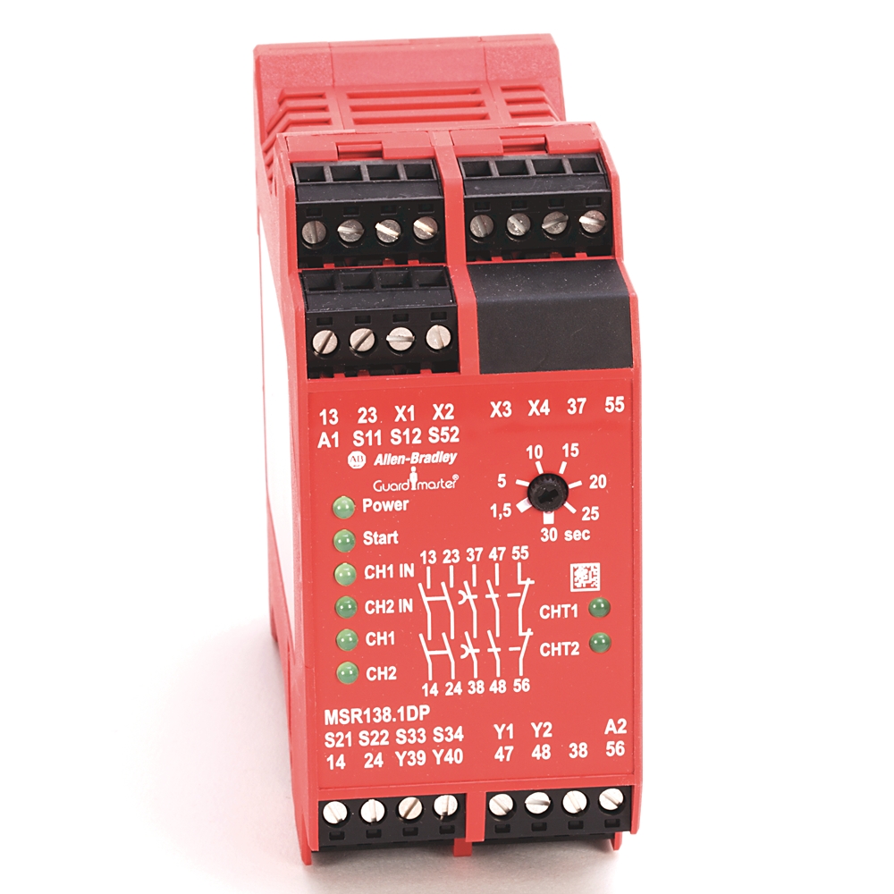
Guardmaster MSR138DP Safety Relay
| Unique Product Identifier |
440R-M23143
|
|---|---|
| UPC |
611320826753
|
| Estimated Lead Time |
5 days
|
| Standard Warranty Duration |
1 year See details |
| Country of Origin |
Multiple
|
The information provided by Rockwell Automation on www.rockwellautomation.com (the “Site”) is for demonstration purposes only and may be incomplete or inaccurate. All information is provided “as is”, and Rockwell Automation makes no representations or warranties of any kind, express or implied, regarding the accuracy, adequacy, validity, reliability, or completeness of any information on the Site. Use of this information is at your own risk.
| Reset |
Automatic/Manual Monitored
|
|---|---|
| Sub Brand |
Guardmaster
|
| Number of outputs, safety related, undelayed, with contact |
2
|
|---|---|
| Number of outputs, safety related, delayed, with contact |
3
|
| Number of outputs, signalling function, undelayed, with contact |
0
|
| Number of outputs, safety related, undelayed, semiconductors |
0
|
| Number of outputs, safety related, delayed, semiconductors |
0
|
| Number of outputs, signalling function, undelayed, semiconductors |
0
|
| Number of outputs, signalling function, delayed, semiconductors |
0
|
| With start input |
True
|
| Voltage type for actuating |
AC/DC
|
| Rated control supply voltage at DC |
24 V
|
| Model |
Basic device
|
| Type of electric connection |
Screw connection
|
| Evaluation inputs |
One- and two-channel
|
| Power ON delay |
1 ms
|
| Input resistance, max |
135 ohm
|
| Power consumption |
4 W
|
| Terminal type |
Removable
|
| Operating voltage range |
20.4
|
| Fuses output |
External: 6 A slow blow or 10 A quick blow
|
| Rated thermal current (Ith) |
7 A maximum in one current path (non-switching)
|
| Continuous safety output current |
UL: B300 , 5 A/250V AC @ 24V DC , AC-15: 6 A/250V AC, DC-13: 3 A/24V DC
|
| Wire size |
0.2 to 2.5 mm²
|
| Electrical life cycle |
100.000 (220V AC/4 A/880VA cosφ = 0.35), 500.000 (220V AC/1.7 A/375VA cosφ = 0.6), 1.000.000 (30V DC/2 A/60 W), 2.000.000 (10V DC/0.01 A/0.1 W)
|
| Number of outputs, signalling function, delayed, with contact |
0
|
| With feedback circuit |
True
|
| Suitable for monitoring of magnetic switches |
True
|
| Suitable for monitoring of proximity switches |
True
|
| Suitable for monitoring of emergency-stop circuits |
True
|
| Suitable for monitoring of optoelectronic protection equipment |
True
|
| Suitable for monitoring of position switches |
True
|
| Suitable for monitoring of tactile sensors |
True
|
| Suitable for monitoring of valves |
True
|
| Switching current, min |
10 mA
|
| Switching voltage, min |
10 V
|
| Rated impulse withstand voltage |
2500 V
|
| Input simultaneity |
Infinite
|
| Safety inputs |
1 N.C., 2 N.C., light curtain
|
| Reset |
Manual monitored or automatic/manual
|
|---|
| Operating temperature |
-5 °C
|
|---|---|
| PFHd |
0.00000000238
|
| Relative humidity |
Operating: 90%
|
| Category |
EN ISO 13849-1: Instantaneous: 4
|
| DC |
Instantaneous: 90%
|
| Pollution degree |
2
|
| T cycle |
8/28800 (h/s)
|
|---|---|
| MTTFd |
Instantaneous: 295
|
| DC avg |
Instantaneous: 90%
|
| Mission time |
20 year
|
| Hours of operation |
24 h
|
| Days of operation |
365 dbays
|
| With detachable clamps |
True
|
|---|---|
| Rated control supply voltage at AC 50 Hz |
24 V
|
| Rated control supply voltage at AC 60 Hz |
24 V
|
| Terminal protection |
IP20, DIN 0470
|
| Enclosure type rating |
IP40 (NEMA 1), DIN 0470
|
| Weight |
350 g
|
| Vibration |
10...55 Hz, 0.35 mm
|
| Shock |
10 G, 16 ms, 100 shocks
|
| Rail mounting possible |
True
|
| Response time |
15 ms
|
| Recovery time |
100 ms
|
| Time delay range |
0.15 s
|
| Enclosure protection |
IP40 (NEMA 1)
|
| Height |
99 mm
|
|---|---|
| Width |
45 mm
|
| Depth |
114.50 mm
|
| Mounting |
35 mm DIN rail in enclosure to a min of IP54
|
| Drawings | |
|---|---|
| 3-Dimensional STEP model (STP) | Download (ZIP) |
| 2-Dimensional Drawing (PDF) | Download (PDF) |
| Product Drawing | Drawing (DWG) |
| Drawings |
|---|
| 3-Dimensional STEP model (STP) Download (ZIP) |
| 2-Dimensional Drawing (PDF) Download (PDF) |
| Product Drawing Drawing (DWG) |
| General | Publication |
|---|---|
| Product Cutsheet | -- |
| Installation Instructions | Publication |
|---|---|
| 440r-in088_-en-p | 440R-IN088 |
| Technical Data | Publication |
|---|---|
| 440r-td001_-en-p | 440R-TD001 |
| User Manual | Publication |
|---|---|
| 440r-um003_-en-p | 440R-UM003 |
This product was certified with the above certifications as of 2026-05-19. Products sold before or after this date might carry different certifications. Please review the product label to check for the certifications your specific product carries.
Looking for certification documents?
Explore certifications for this product and more in our comprehensive Literature Library.
| EU Importer Address |
Rockwell Automation N.V |
|---|---|
| EU Authorized Representative Address |
Rockwell Automation N.V |
| Technotes |
|---|
Overview
| Unique Product Identifier |
440R-M23143
|
|---|---|
| UPC |
611320826753
|
| Estimated Lead Time |
5 days
|
| Standard Warranty Duration |
1 year See details |
| Country of Origin |
Multiple
|
The information provided by Rockwell Automation on www.rockwellautomation.com (the “Site”) is for demonstration purposes only and may be incomplete or inaccurate. All information is provided “as is”, and Rockwell Automation makes no representations or warranties of any kind, express or implied, regarding the accuracy, adequacy, validity, reliability, or completeness of any information on the Site. Use of this information is at your own risk.
Electrical & Connectivity
| Reset |
Automatic/Manual Monitored
|
|---|---|
| Sub Brand |
Guardmaster
|
| Number of outputs, safety related, undelayed, with contact |
2
|
|---|---|
| Number of outputs, safety related, delayed, with contact |
3
|
| Number of outputs, signalling function, undelayed, with contact |
0
|
| Number of outputs, safety related, undelayed, semiconductors |
0
|
| Number of outputs, safety related, delayed, semiconductors |
0
|
| Number of outputs, signalling function, undelayed, semiconductors |
0
|
| Number of outputs, signalling function, delayed, semiconductors |
0
|
| With start input |
True
|
| Voltage type for actuating |
AC/DC
|
| Rated control supply voltage at DC |
24 V
|
| Model |
Basic device
|
| Type of electric connection |
Screw connection
|
| Evaluation inputs |
One- and two-channel
|
| Power ON delay |
1 ms
|
| Input resistance, max |
135 ohm
|
| Power consumption |
4 W
|
| Terminal type |
Removable
|
| Operating voltage range |
20.4
|
| Fuses output |
External: 6 A slow blow or 10 A quick blow
|
| Rated thermal current (Ith) |
7 A maximum in one current path (non-switching)
|
| Continuous safety output current |
UL: B300 , 5 A/250V AC @ 24V DC , AC-15: 6 A/250V AC, DC-13: 3 A/24V DC
|
| Wire size |
0.2 to 2.5 mm²
|
| Electrical life cycle |
100.000 (220V AC/4 A/880VA cosφ = 0.35), 500.000 (220V AC/1.7 A/375VA cosφ = 0.6), 1.000.000 (30V DC/2 A/60 W), 2.000.000 (10V DC/0.01 A/0.1 W)
|
| Number of outputs, signalling function, delayed, with contact |
0
|
| With feedback circuit |
True
|
| Suitable for monitoring of magnetic switches |
True
|
| Suitable for monitoring of proximity switches |
True
|
| Suitable for monitoring of emergency-stop circuits |
True
|
| Suitable for monitoring of optoelectronic protection equipment |
True
|
| Suitable for monitoring of position switches |
True
|
| Suitable for monitoring of tactile sensors |
True
|
| Suitable for monitoring of valves |
True
|
| Switching current, min |
10 mA
|
| Switching voltage, min |
10 V
|
| Rated impulse withstand voltage |
2500 V
|
| Input simultaneity |
Infinite
|
| Safety inputs |
1 N.C., 2 N.C., light curtain
|
| Reset |
Manual monitored or automatic/manual
|
|---|
Compliance & Environment
| Operating temperature |
-5 °C
|
|---|---|
| PFHd |
0.00000000238
|
| Relative humidity |
Operating: 90%
|
| Category |
EN ISO 13849-1: Instantaneous: 4
|
| DC |
Instantaneous: 90%
|
| Pollution degree |
2
|
Technical Specifications
| T cycle |
8/28800 (h/s)
|
|---|---|
| MTTFd |
Instantaneous: 295
|
| DC avg |
Instantaneous: 90%
|
| Mission time |
20 year
|
| Hours of operation |
24 h
|
| Days of operation |
365 dbays
|
Physical Characteristics
| With detachable clamps |
True
|
|---|---|
| Rated control supply voltage at AC 50 Hz |
24 V
|
| Rated control supply voltage at AC 60 Hz |
24 V
|
| Terminal protection |
IP20, DIN 0470
|
| Enclosure type rating |
IP40 (NEMA 1), DIN 0470
|
| Weight |
350 g
|
| Vibration |
10...55 Hz, 0.35 mm
|
| Shock |
10 G, 16 ms, 100 shocks
|
| Rail mounting possible |
True
|
| Response time |
15 ms
|
| Recovery time |
100 ms
|
| Time delay range |
0.15 s
|
| Enclosure protection |
IP40 (NEMA 1)
|
| Height |
99 mm
|
|---|---|
| Width |
45 mm
|
| Depth |
114.50 mm
|
| Mounting |
35 mm DIN rail in enclosure to a min of IP54
|
Drawings
| Drawings | |
|---|---|
| 3-Dimensional STEP model (STP) | Download (ZIP) |
| 2-Dimensional Drawing (PDF) | Download (PDF) |
| Product Drawing | Drawing (DWG) |
| Drawings |
|---|
| 3-Dimensional STEP model (STP) Download (ZIP) |
| 2-Dimensional Drawing (PDF) Download (PDF) |
| Product Drawing Drawing (DWG) |
Documents
|
Product Cutsheet
General
-- |
|
440r-in088_-en-p
Installation Instructions
440R-IN088 |
|
440r-td001_-en-p
Technical Data
440R-TD001 |
|
440r-um003_-en-p
User Manual
440R-UM003 |
| General | Publication |
|---|---|
| Product Cutsheet | -- |
| Installation Instructions | Publication |
| 440r-in088_-en-p | 440R-IN088 |
| Technical Data | Publication |
| 440r-td001_-en-p | 440R-TD001 |
| User Manual | Publication |
| 440r-um003_-en-p | 440R-UM003 |
Certifications
This product was certified with the above certifications as of 2026-05-19. Products sold before or after this date might carry different certifications. Please review the product label to check for the certifications your specific product carries.
Looking for certification documents?
Explore certifications for this product and more in our comprehensive Literature Library.
| EU Importer Address |
Rockwell Automation N.V |
|---|---|
| EU Authorized Representative Address |
Rockwell Automation N.V |
Accessories
Alternative Products
Technotes
| Technotes |
|---|