View all 440R Guardmaster Safety Relays
Preferred
,
440r-gl2s2t
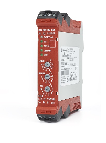
Guardmaster GLT Safety Relay
Serial #:
This product has not been verified. Please register your product to confirm authenticity.
Lifecycle status:
Active
Lifecycle status:
Active
Technical Specifications
Electrical
Certification
Mechanical
SIL Rating
Performance Level
Environmental
Construction
Drawings
Documents
Certifications
Accessories
Alternative Products
Technotes
| Number of outputs, safety related, undelayed, with contact |
0
|
|---|---|
| Number of outputs, safety related, delayed, with contact |
0
|
| Number of outputs, signalling function, undelayed, with contact |
0
|
| Number of outputs, safety related, undelayed, semiconductors |
2
|
| Number of outputs, safety related, delayed, semiconductors |
2
|
| Number of outputs, signalling function, undelayed, semiconductors |
1
|
| Number of outputs, signalling function, delayed, semiconductors |
0
|
| With start input |
False
|
| With muting function |
False
|
| Voltage type for actuating |
DC
|
| Rated control supply voltage at DC |
24 V
|
| Model |
Basic device
|
| Type of electric connection |
Screw connection
|
| Evaluation inputs |
Other
|
| Power consumption |
2 W
|
| Operating voltage range |
20.4
|
| Configurable logic |
Lock control + time delay
|
| Continuous safety output current |
0.5 A
|
| Wire size |
0.2...2.5 mm² (24...14 AWG)
|
| Number of outputs, signalling function, delayed, with contact |
0
|
| With feedback circuit |
True
|
| Suitable for monitoring of magnetic switches |
True
|
| Suitable for monitoring of proximity switches |
True
|
| Suitable for monitoring of emergency-stop circuits |
True
|
| Suitable for monitoring of optoelectronic protection equipment |
True
|
| Suitable for monitoring of position switches |
True
|
| Suitable for monitoring of tactile sensors |
True
|
| Suitable for monitoring of valves |
True
|
| Surge auxillary output current duration, max |
5 ms
|
| Surge safety output current duration |
5 ms
|
| Special output surge safety output current |
3 A
|
| Continuous auxiliary output current |
50 mA
|
| Special output output current duration |
10 µs
|
| Surge auxiliary output current |
700 mA
|
| Surge safety output current |
1.5 A
|
| Special output continuous safety output current |
0.3 A
|
| Aggregate current of outputs per module |
1.8 A
|
| Other input |
SWS input
|
| Other output |
SWS output
|
| SIL according to IEC 61508 |
3
|
|---|---|
| With approval according to UL |
True
|
| Stop category according to IEC 60204 |
0
|
| Performance level according to EN ISO 13849-1 |
Level e
|
| Type of safety according to IEC 61496-1 |
4
|
| With approval for TUV |
True
|
| With detachable clamps |
True
|
|---|---|
| Rated control supply voltage at AC 50 Hz |
0 V
|
| Rated control supply voltage at AC 60 Hz |
0 V
|
| Vibration |
10...55 Hz, 0.35 mm
|
| Shock |
10 G
|
| Release-delay |
0 s
|
| Rail mounting possible |
True
|
| Enclosure protection |
IP40 (NEMA 1)
|
| Safety integrity level claim limit |
3
|
|---|---|
| Safe failure fraction |
99 %
|
| PFHd |
8.11 E-9
|
| Mode of operation |
High demand
|
| Category |
Up to 4
|
| PFD |
1.43 E-3
|
| Hardware fault tolerance |
1
|
| DC avg |
99 %
|
|---|---|
| T cycle |
8/28.8 (h/s)
|
| Mission time |
20 year
|
| Hours of operation |
24 h
|
| Days of operation |
365 dbays
|
| Performance level |
Up to e
|
| Evaluation input |
SWS input
|
| Operating temperature |
-5 °C
|
|---|---|
| Relative humidity |
Operating: 90%
|
| Height |
119.14 mm
|
|---|---|
| Width |
22.5 mm
|
| Depth |
113.6 mm
|
| Drawings | |
|---|---|
| Electrical Wiring Diagram (DWG) | Download (ZIP) |
| 3-Dimensional STEP model (STP) | Download (ZIP) |
| 2-Dimensional Drawing (PDF) | Download (PDF) |
| Product Drawing | Drawing (DXF) |
| Drawings |
|---|
| Electrical Wiring Diagram (DWG) Download (ZIP) |
| 3-Dimensional STEP model (STP) Download (ZIP) |
| 2-Dimensional Drawing (PDF) Download (PDF) |
| Product Drawing Drawing (DXF) |
| General | Publication |
|---|---|
| Electrical Wiring Diagram (PDF) | -- |
| User Manual | -- |
| Product Cutsheet | -- |
| Technical Data | Publication |
|---|---|
| 440r-td001_-en-p | 440R-TD001 |
Looking for more documentation?
Find curated technical documentation for this product in the Technical Documentation Center, or search our full Literature Library.
Visit the Technical Documentation Center
Search the Literature Library
- Korean KC
This product was certified with the above certifications as of {}. Products sold before or after this date might carry different certifications. Please review the product label to check for the certifications your specific product carries.
Items Per Page:
Items Per Page:
| Technotes |
|---|
Looking for more Technotes?
Find questions and answers from Rockwell Automation technical experts for this product in our Knowledgebase.
Search Knowledgebase
Technical Specifications
| Number of outputs, safety related, undelayed, with contact |
0
|
|---|---|
| Number of outputs, safety related, delayed, with contact |
0
|
| Number of outputs, signalling function, undelayed, with contact |
0
|
| Number of outputs, safety related, undelayed, semiconductors |
2
|
| Number of outputs, safety related, delayed, semiconductors |
2
|
| Number of outputs, signalling function, undelayed, semiconductors |
1
|
| Number of outputs, signalling function, delayed, semiconductors |
0
|
| With start input |
False
|
| With muting function |
False
|
| Voltage type for actuating |
DC
|
| Rated control supply voltage at DC |
24 V
|
| Model |
Basic device
|
| Type of electric connection |
Screw connection
|
| Evaluation inputs |
Other
|
| Power consumption |
2 W
|
| Operating voltage range |
20.4
|
| Configurable logic |
Lock control + time delay
|
| Continuous safety output current |
0.5 A
|
| Wire size |
0.2...2.5 mm² (24...14 AWG)
|
| Number of outputs, signalling function, delayed, with contact |
0
|
| With feedback circuit |
True
|
| Suitable for monitoring of magnetic switches |
True
|
| Suitable for monitoring of proximity switches |
True
|
| Suitable for monitoring of emergency-stop circuits |
True
|
| Suitable for monitoring of optoelectronic protection equipment |
True
|
| Suitable for monitoring of position switches |
True
|
| Suitable for monitoring of tactile sensors |
True
|
| Suitable for monitoring of valves |
True
|
| Surge auxillary output current duration, max |
5 ms
|
| Surge safety output current duration |
5 ms
|
| Special output surge safety output current |
3 A
|
| Continuous auxiliary output current |
50 mA
|
| Special output output current duration |
10 µs
|
| Surge auxiliary output current |
700 mA
|
| Surge safety output current |
1.5 A
|
| Special output continuous safety output current |
0.3 A
|
| Aggregate current of outputs per module |
1.8 A
|
| Other input |
SWS input
|
| Other output |
SWS output
|
| SIL according to IEC 61508 |
3
|
|---|---|
| With approval according to UL |
True
|
| Stop category according to IEC 60204 |
0
|
| Performance level according to EN ISO 13849-1 |
Level e
|
| Type of safety according to IEC 61496-1 |
4
|
| With approval for TUV |
True
|
| With detachable clamps |
True
|
|---|---|
| Rated control supply voltage at AC 50 Hz |
0 V
|
| Rated control supply voltage at AC 60 Hz |
0 V
|
| Vibration |
10...55 Hz, 0.35 mm
|
| Shock |
10 G
|
| Release-delay |
0 s
|
| Rail mounting possible |
True
|
| Enclosure protection |
IP40 (NEMA 1)
|
| Safety integrity level claim limit |
3
|
|---|---|
| Safe failure fraction |
99 %
|
| PFHd |
8.11 E-9
|
| Mode of operation |
High demand
|
| Category |
Up to 4
|
| PFD |
1.43 E-3
|
| Hardware fault tolerance |
1
|
| DC avg |
99 %
|
|---|---|
| T cycle |
8/28.8 (h/s)
|
| Mission time |
20 year
|
| Hours of operation |
24 h
|
| Days of operation |
365 dbays
|
| Performance level |
Up to e
|
| Evaluation input |
SWS input
|
| Operating temperature |
-5 °C
|
|---|---|
| Relative humidity |
Operating: 90%
|
| Height |
119.14 mm
|
|---|---|
| Width |
22.5 mm
|
| Depth |
113.6 mm
|
Drawings
| Drawings | |
|---|---|
| Electrical Wiring Diagram (DWG) | Download (ZIP) |
| 3-Dimensional STEP model (STP) | Download (ZIP) |
| 2-Dimensional Drawing (PDF) | Download (PDF) |
| Product Drawing | Drawing (DXF) |
| Drawings |
|---|
| Electrical Wiring Diagram (DWG) Download (ZIP) |
| 3-Dimensional STEP model (STP) Download (ZIP) |
| 2-Dimensional Drawing (PDF) Download (PDF) |
| Product Drawing Drawing (DXF) |
Documents
|
Electrical Wiring Diagram (PDF)
General
-- |
|
User Manual
General
-- |
|
Product Cutsheet
General
-- |
|
440r-td001_-en-p
Technical Data
440R-TD001 |
| General | Publication |
|---|---|
| Electrical Wiring Diagram (PDF) | -- |
| User Manual | -- |
| Product Cutsheet | -- |
| Technical Data | Publication |
| 440r-td001_-en-p | 440R-TD001 |
Looking for more documentation?
Find curated technical documentation for this product in the Technical Documentation Center, or search our full Literature Library.
Visit the Technical Documentation Center
Search the Literature Library
Certifications
- Korean KC
This product was certified with the above certifications as of {}. Products sold before or after this date might carry different certifications. Please review the product label to check for the certifications your specific product carries.
Accessories
Items Per Page:
Alternative Products
Items Per Page:
Technotes
| Technotes |
|---|
Looking for more Technotes?
Find questions and answers from Rockwell Automation technical experts for this product in our Knowledgebase.
Search Knowledgebase
Guardmaster GLT Safety Relay
440r-gl2s2t
Close
Print
Copyright ©2026 Rockwell Automation, Inc.