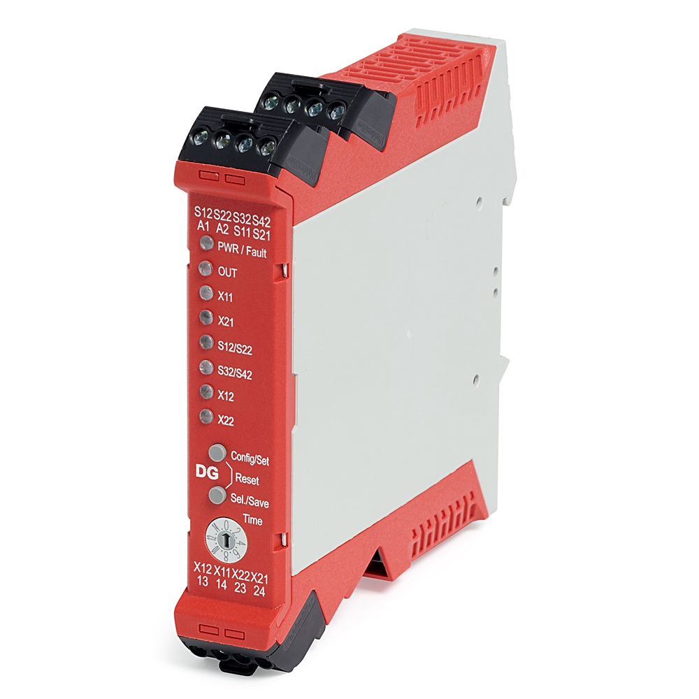
Guardmaster Dual GuardLink Safety Relay
| Unique Product Identifier |
440R-DG2R2T
|
|---|---|
| UPC |
889508597287
|
| Estimated Lead Time |
5 days
|
| Standard Warranty Duration |
1 year See details |
| Country of Origin |
Multiple
|
The information provided by Rockwell Automation on www.rockwellautomation.com (the “Site”) is for demonstration purposes only and may be incomplete or inaccurate. All information is provided “as is”, and Rockwell Automation makes no representations or warranties of any kind, express or implied, regarding the accuracy, adequacy, validity, reliability, or completeness of any information on the Site. Use of this information is at your own risk.
| Output |
2 Normally Open
|
|---|---|
| Power Supply |
24V DC
|
| Number of outputs, safety related, undelayed, with contact |
2
|
|---|---|
| Number of outputs, safety related, delayed, with contact |
0
|
| Number of outputs, signalling function, undelayed, with contact |
0
|
| Number of outputs, safety related, undelayed, semiconductors |
0
|
| Number of outputs, safety related, delayed, semiconductors |
0
|
| Number of outputs, signalling function, undelayed, semiconductors |
1
|
| Number of outputs, signalling function, delayed, semiconductors |
0
|
| With start input |
False
|
| With muting function |
False
|
| Voltage type for actuating |
DC
|
| Rated control supply voltage at DC |
24 V
|
| Model |
Basic device
|
| Type of electric connection |
Screw connection
|
| Evaluation inputs |
Other
|
| Power consumption |
3.5 W
|
| Operating voltage range |
20.4
|
| Safety output rating |
UL: C300, AC-15: 1.5 A/250V AC, DC-13: 2 A/24V DC (0.1 Hz)
|
| Wire size |
0.2...2.5 mm² (24...14 AWG)
|
| Number of outputs, signalling function, delayed, with contact |
0
|
| With feedback circuit |
True
|
| Suitable for monitoring of magnetic switches |
True
|
| Suitable for monitoring of proximity switches |
True
|
| Suitable for monitoring of emergency-stop circuits |
True
|
| Suitable for monitoring of optoelectronic protection equipment |
True
|
| Suitable for monitoring of position switches |
True
|
| Suitable for monitoring of tactile sensors |
True
|
| Suitable for monitoring of valves |
True
|
| Surge auxillary output current duration, max |
5 ms
|
| Aggregate current of outputs per module, max |
6 A
|
| Surge output current duration, max |
5 ms
|
| Continuous auxiliary output current |
50 mA
|
| Continuous output current, max |
50 mA
|
| Surge output current, max |
700 mA
|
| Surge Aux output current |
700 mA
|
| Other input |
SWS input
|
| Other output |
SWS output
|
| Safety integrity level claim limit |
3
|
|---|---|
| Safe failure fraction |
98.9 %
|
| Operating temperature |
-5 °C
|
| PFHd |
11.2
|
| Mode of operation |
High demand mode
|
| Relative humidity |
90%
|
| Category |
Up to 4
|
| Hardware fault tolerance |
HFT = 1 (dual channel system) HFT = 0 (single channel system)
|
| DC |
97.12 %
|
| Safety related subsystems |
Type B (use of progmable/complex components)
|
| MTTFd |
92.2 year
|
|---|---|
| DC avg |
97.31 %
|
| T cycle |
8/28.8 (h/s)
|
| Mission time |
20 year
|
| Hours of operation |
24 h
|
| Proof test interval,max (a) |
20 %
|
| CCF |
80
|
| Days of operation |
365 dbays
|
| SSF |
99.06 %
|
| Performance level |
Up to e
|
| With detachable clamps |
True
|
|---|---|
| Rated control supply voltage at AC 50 Hz |
0 V
|
| Rated control supply voltage at AC 60 Hz |
0 V
|
| Height |
119.4 mm
|
| Width |
22.5 mm
|
| Depth |
113.6 mm
|
| Vibration |
10...55 Hz, 0.35 mm
|
| Shock |
10 g, 16 ms
|
| Release-delay |
0 s
|
| Rail mounting possible |
True
|
| Mechanical life operations |
1.0E7
|
| Enclosure protection |
IP40 (NEMA 1)
|
| Drawings | |
|---|---|
| 3-Dimensional STEP model (STP) | Download (ZIP) |
| Product Drawing | Drawing (DWG) |
| Drawings |
|---|
| 3-Dimensional STEP model (STP) Download (ZIP) |
| Product Drawing Drawing (DWG) |
| General | Publication |
|---|---|
| Product Cutsheet | -- |
| User Manual | -- |
| Link to Product Certification - TUV | -- |
| Technical Data | Publication |
|---|---|
| 440r-td001_-en-p | 440R-TD001 |
| User Manual | Publication |
|---|---|
| 440r-um015_-en-p | 440R-UM015 |
| Technotes |
|---|
Overview
| Unique Product Identifier |
440R-DG2R2T
|
|---|---|
| UPC |
889508597287
|
| Estimated Lead Time |
5 days
|
| Standard Warranty Duration |
1 year See details |
| Country of Origin |
Multiple
|
The information provided by Rockwell Automation on www.rockwellautomation.com (the “Site”) is for demonstration purposes only and may be incomplete or inaccurate. All information is provided “as is”, and Rockwell Automation makes no representations or warranties of any kind, express or implied, regarding the accuracy, adequacy, validity, reliability, or completeness of any information on the Site. Use of this information is at your own risk.
Electrical & Connectivity
| Output |
2 Normally Open
|
|---|---|
| Power Supply |
24V DC
|
| Number of outputs, safety related, undelayed, with contact |
2
|
|---|---|
| Number of outputs, safety related, delayed, with contact |
0
|
| Number of outputs, signalling function, undelayed, with contact |
0
|
| Number of outputs, safety related, undelayed, semiconductors |
0
|
| Number of outputs, safety related, delayed, semiconductors |
0
|
| Number of outputs, signalling function, undelayed, semiconductors |
1
|
| Number of outputs, signalling function, delayed, semiconductors |
0
|
| With start input |
False
|
| With muting function |
False
|
| Voltage type for actuating |
DC
|
| Rated control supply voltage at DC |
24 V
|
| Model |
Basic device
|
| Type of electric connection |
Screw connection
|
| Evaluation inputs |
Other
|
| Power consumption |
3.5 W
|
| Operating voltage range |
20.4
|
| Safety output rating |
UL: C300, AC-15: 1.5 A/250V AC, DC-13: 2 A/24V DC (0.1 Hz)
|
| Wire size |
0.2...2.5 mm² (24...14 AWG)
|
| Number of outputs, signalling function, delayed, with contact |
0
|
| With feedback circuit |
True
|
| Suitable for monitoring of magnetic switches |
True
|
| Suitable for monitoring of proximity switches |
True
|
| Suitable for monitoring of emergency-stop circuits |
True
|
| Suitable for monitoring of optoelectronic protection equipment |
True
|
| Suitable for monitoring of position switches |
True
|
| Suitable for monitoring of tactile sensors |
True
|
| Suitable for monitoring of valves |
True
|
| Surge auxillary output current duration, max |
5 ms
|
| Aggregate current of outputs per module, max |
6 A
|
| Surge output current duration, max |
5 ms
|
| Continuous auxiliary output current |
50 mA
|
| Continuous output current, max |
50 mA
|
| Surge output current, max |
700 mA
|
| Surge Aux output current |
700 mA
|
| Other input |
SWS input
|
| Other output |
SWS output
|
Compliance & Environment
| Safety integrity level claim limit |
3
|
|---|---|
| Safe failure fraction |
98.9 %
|
| Operating temperature |
-5 °C
|
| PFHd |
11.2
|
| Mode of operation |
High demand mode
|
| Relative humidity |
90%
|
| Category |
Up to 4
|
| Hardware fault tolerance |
HFT = 1 (dual channel system) HFT = 0 (single channel system)
|
| DC |
97.12 %
|
| Safety related subsystems |
Type B (use of progmable/complex components)
|
Technical Specifications
| MTTFd |
92.2 year
|
|---|---|
| DC avg |
97.31 %
|
| T cycle |
8/28.8 (h/s)
|
| Mission time |
20 year
|
| Hours of operation |
24 h
|
| Proof test interval,max (a) |
20 %
|
| CCF |
80
|
| Days of operation |
365 dbays
|
| SSF |
99.06 %
|
| Performance level |
Up to e
|
Physical Characteristics
| With detachable clamps |
True
|
|---|---|
| Rated control supply voltage at AC 50 Hz |
0 V
|
| Rated control supply voltage at AC 60 Hz |
0 V
|
| Height |
119.4 mm
|
| Width |
22.5 mm
|
| Depth |
113.6 mm
|
| Vibration |
10...55 Hz, 0.35 mm
|
| Shock |
10 g, 16 ms
|
| Release-delay |
0 s
|
| Rail mounting possible |
True
|
| Mechanical life operations |
1.0E7
|
| Enclosure protection |
IP40 (NEMA 1)
|
Drawings
| Drawings | |
|---|---|
| 3-Dimensional STEP model (STP) | Download (ZIP) |
| Product Drawing | Drawing (DWG) |
| Drawings |
|---|
| 3-Dimensional STEP model (STP) Download (ZIP) |
| Product Drawing Drawing (DWG) |
Documents
|
Product Cutsheet
General
-- |
|
User Manual
General
-- |
|
Link to Product Certification - TUV
General
-- |
|
440r-td001_-en-p
Technical Data
440R-TD001 |
|
440r-um015_-en-p
User Manual
440R-UM015 |
| General | Publication |
|---|---|
| Product Cutsheet | -- |
| User Manual | -- |
| Link to Product Certification - TUV | -- |
| Technical Data | Publication |
| 440r-td001_-en-p | 440R-TD001 |
| User Manual | Publication |
| 440r-um015_-en-p | 440R-UM015 |
Downloads
Technotes
| Technotes |
|---|