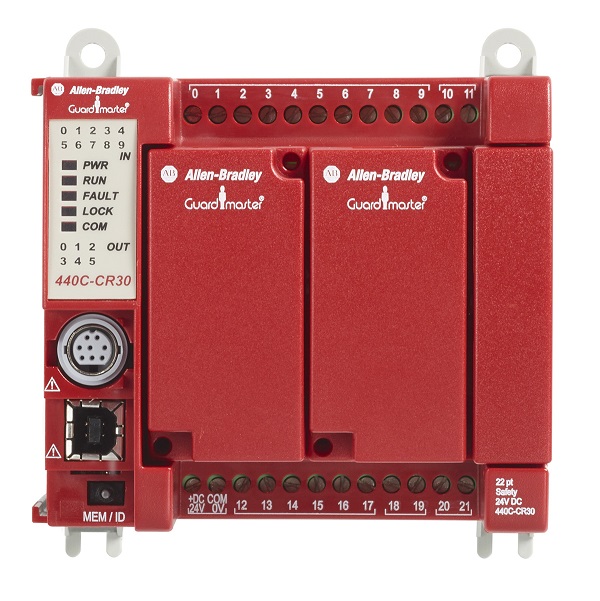
Guardmaster 440C-CR30 safety relay
| Unique Product Identifier |
440C-CR30-22BBB
|
|---|---|
| UPC |
885630966694
|
| Estimated Lead Time |
43 days
|
| Standard Warranty Duration |
1 year See details |
| Country of Origin |
Multiple
|
The information provided by Rockwell Automation on www.rockwellautomation.com (the “Site”) is for demonstration purposes only and may be incomplete or inaccurate. All information is provided “as is”, and Rockwell Automation makes no representations or warranties of any kind, express or implied, regarding the accuracy, adequacy, validity, reliability, or completeness of any information on the Site. Use of this information is at your own risk.
| Communication |
Modbus
|
|---|---|
| Interface |
USB Port, non-isolated RS232
|
| Output |
Up to 10, 4 dedicated, 6
|
| Power Supply |
24V DC
|
| Temperature Rating |
-5…55 °C (23…131 °F)
|
| Number of outputs, safety related, undelayed, with contact |
0
|
|---|---|
| Number of outputs, safety related, delayed, with contact |
0
|
| Number of outputs, signalling function, undelayed, with contact |
0
|
| Number of outputs, safety related, undelayed, semiconductors |
10
|
| Number of outputs, safety related, delayed, semiconductors |
10
|
| Number of outputs, signalling function, undelayed, semiconductors |
10
|
| Number of outputs, signalling function, delayed, semiconductors |
10
|
| With start input |
True
|
| With muting function |
True
|
| Voltage type for actuating |
DC
|
| Rated control supply voltage at DC |
24 V
|
| Model |
Basic device
|
| Type of electric connection |
Screw connection
|
| Evaluation inputs |
Other
|
| Power consumption |
5.28 W
|
| Continuous output current |
0.5 A @ terminals 12...19
|
| Configurable logic |
List function blocks like, two hand control
|
| Wire size |
0.2...2.5 mm² (24...14 AWG) solid/stranded copper wire @ 90 °C (194 °F) insulation maximum
|
| Number of outputs, signalling function, delayed, with contact |
0
|
| With feedback circuit |
True
|
| Suitable for monitoring of magnetic switches |
True
|
| Suitable for monitoring of proximity switches |
True
|
| Suitable for monitoring of emergency-stop circuits |
True
|
| Suitable for monitoring of optoelectronic protection equipment |
True
|
| Suitable for monitoring of position switches |
True
|
| Suitable for monitoring of tactile sensors |
True
|
| Suitable for monitoring of valves |
True
|
| Surge output current |
1 A
|
| Surge output current duration |
5 ms
|
| Aggregate current of outputs per device, max |
3 A
|
| Other output |
SWS output
|
| Operating voltage |
20.4 V
|
| Safety integrity level claim limit |
3
|
|---|---|
| Operating temperature |
-5 °C
|
| Mode of operation |
High demand mode
|
| Emissions |
Group 1, Class A
|
| Relative humidity |
90%
|
| Category |
Up to 4
|
| PFD |
1.76E-03 (whole safety function)
|
| ESD immunity |
6 kV contact discharges, 8 kV air discharges
|
| Hardware fault tolerance |
HFT = 1 (two channel system)
|
| EFT/B immunity |
On ethernet port: ±1kV @ 5kHz
|
| Surge transient immunity |
On ethernet port: ±1 kV line-earth(CM)
|
| Radiated RF immunity |
10 V/m with 1 kHz sine-wave 80% AM from 80...2700 MHz 10 V/m with 200 Hz 50% pulse 100% AM @ 900 MHz 10 V/m with 200 Hz 50% Pulse 100% AM @ 1890 MHz
|
| PFH |
1.00E-08
|
| Safe failure fraction |
90 %
|
| Storage temperature |
-40 °C
|
| Safety related subsystems |
Type B (use of progmable/complex components)
|
| Conducted RF immunity |
10V RMS with 1 kHz sine-wave 80% AM from 150 kHz...80 MHz
|
| With detachable clamps |
False
|
|---|---|
| Rated control supply voltage at AC 50 Hz |
0 V
|
| Rated control supply voltage at AC 60 Hz |
0 V
|
| Enclosure type rating |
IP20
|
| Vibration |
10...55 Hz, 0.35 mm (0.014 in)
|
| Shock |
Shock proof, operating: 10 G (0.35 oz), 16 ms
|
| Rail mounting possible |
True
|
| Height |
90 mm
|
|---|---|
| Width |
100 mm
|
| Depth |
80 mm
|
| Performance level |
Up to e
|
|---|---|
| Evaluation input |
SWS input
|
| Drawings | |
|---|---|
| 3-Dimensional STEP model (STP) | Download (ZIP) |
| Product Drawing | Drawing (DXF) |
| Drawings |
|---|
| 3-Dimensional STEP model (STP) Download (ZIP) |
| Product Drawing Drawing (DXF) |
| General | Publication |
|---|---|
| Link to Online Catalog | -- |
| Link to Application Examples Brochure | 440C-PP001 |
| Product Cutsheet | -- |
| Technical Data | Publication |
|---|---|
| safety-sr001_-en-e | SAFETY-SR001 |
| User Manual | Publication |
|---|---|
| 440c-um001_-en-p | 440C-UM001 |
- Firmware for 440C-CR30-22BBB v10.011
- Documentation for 440C-CR30-22BBB v10.011
| Technotes |
|---|
Overview
| Unique Product Identifier |
440C-CR30-22BBB
|
|---|---|
| UPC |
885630966694
|
| Estimated Lead Time |
43 days
|
| Standard Warranty Duration |
1 year See details |
| Country of Origin |
Multiple
|
The information provided by Rockwell Automation on www.rockwellautomation.com (the “Site”) is for demonstration purposes only and may be incomplete or inaccurate. All information is provided “as is”, and Rockwell Automation makes no representations or warranties of any kind, express or implied, regarding the accuracy, adequacy, validity, reliability, or completeness of any information on the Site. Use of this information is at your own risk.
Electrical & Connectivity
| Communication |
Modbus
|
|---|---|
| Interface |
USB Port, non-isolated RS232
|
| Output |
Up to 10, 4 dedicated, 6
|
| Power Supply |
24V DC
|
| Temperature Rating |
-5…55 °C (23…131 °F)
|
| Number of outputs, safety related, undelayed, with contact |
0
|
|---|---|
| Number of outputs, safety related, delayed, with contact |
0
|
| Number of outputs, signalling function, undelayed, with contact |
0
|
| Number of outputs, safety related, undelayed, semiconductors |
10
|
| Number of outputs, safety related, delayed, semiconductors |
10
|
| Number of outputs, signalling function, undelayed, semiconductors |
10
|
| Number of outputs, signalling function, delayed, semiconductors |
10
|
| With start input |
True
|
| With muting function |
True
|
| Voltage type for actuating |
DC
|
| Rated control supply voltage at DC |
24 V
|
| Model |
Basic device
|
| Type of electric connection |
Screw connection
|
| Evaluation inputs |
Other
|
| Power consumption |
5.28 W
|
| Continuous output current |
0.5 A @ terminals 12...19
|
| Configurable logic |
List function blocks like, two hand control
|
| Wire size |
0.2...2.5 mm² (24...14 AWG) solid/stranded copper wire @ 90 °C (194 °F) insulation maximum
|
| Number of outputs, signalling function, delayed, with contact |
0
|
| With feedback circuit |
True
|
| Suitable for monitoring of magnetic switches |
True
|
| Suitable for monitoring of proximity switches |
True
|
| Suitable for monitoring of emergency-stop circuits |
True
|
| Suitable for monitoring of optoelectronic protection equipment |
True
|
| Suitable for monitoring of position switches |
True
|
| Suitable for monitoring of tactile sensors |
True
|
| Suitable for monitoring of valves |
True
|
| Surge output current |
1 A
|
| Surge output current duration |
5 ms
|
| Aggregate current of outputs per device, max |
3 A
|
| Other output |
SWS output
|
| Operating voltage |
20.4 V
|
Compliance & Environment
| Safety integrity level claim limit |
3
|
|---|---|
| Operating temperature |
-5 °C
|
| Mode of operation |
High demand mode
|
| Emissions |
Group 1, Class A
|
| Relative humidity |
90%
|
| Category |
Up to 4
|
| PFD |
1.76E-03 (whole safety function)
|
| ESD immunity |
6 kV contact discharges, 8 kV air discharges
|
| Hardware fault tolerance |
HFT = 1 (two channel system)
|
| EFT/B immunity |
On ethernet port: ±1kV @ 5kHz
|
| Surge transient immunity |
On ethernet port: ±1 kV line-earth(CM)
|
| Radiated RF immunity |
10 V/m with 1 kHz sine-wave 80% AM from 80...2700 MHz 10 V/m with 200 Hz 50% pulse 100% AM @ 900 MHz 10 V/m with 200 Hz 50% Pulse 100% AM @ 1890 MHz
|
| PFH |
1.00E-08
|
| Safe failure fraction |
90 %
|
| Storage temperature |
-40 °C
|
| Safety related subsystems |
Type B (use of progmable/complex components)
|
| Conducted RF immunity |
10V RMS with 1 kHz sine-wave 80% AM from 150 kHz...80 MHz
|
Physical Characteristics
| With detachable clamps |
False
|
|---|---|
| Rated control supply voltage at AC 50 Hz |
0 V
|
| Rated control supply voltage at AC 60 Hz |
0 V
|
| Enclosure type rating |
IP20
|
| Vibration |
10...55 Hz, 0.35 mm (0.014 in)
|
| Shock |
Shock proof, operating: 10 G (0.35 oz), 16 ms
|
| Rail mounting possible |
True
|
| Height |
90 mm
|
|---|---|
| Width |
100 mm
|
| Depth |
80 mm
|
Technical Specifications
| Performance level |
Up to e
|
|---|---|
| Evaluation input |
SWS input
|
Drawings
| Drawings | |
|---|---|
| 3-Dimensional STEP model (STP) | Download (ZIP) |
| Product Drawing | Drawing (DXF) |
| Drawings |
|---|
| 3-Dimensional STEP model (STP) Download (ZIP) |
| Product Drawing Drawing (DXF) |
Documents
|
Link to Online Catalog
General
-- |
|
Link to Application Examples Brochure
General
440C-PP001 |
|
Product Cutsheet
General
-- |
|
safety-sr001_-en-e
Technical Data
SAFETY-SR001 |
|
440c-um001_-en-p
User Manual
440C-UM001 |
| General | Publication |
|---|---|
| Link to Online Catalog | -- |
| Link to Application Examples Brochure | 440C-PP001 |
| Product Cutsheet | -- |
| Technical Data | Publication |
| safety-sr001_-en-e | SAFETY-SR001 |
| User Manual | Publication |
| 440c-um001_-en-p | 440C-UM001 |
Downloads
- Firmware for 440C-CR30-22BBB v10.011
- Documentation for 440C-CR30-22BBB v10.011
Alternative Products
Technotes
| Technotes |
|---|