| Enclosure Type | Open Style |
|---|
| Number of auxiliary contacts as normally open contact | 1 |
|---|---|
| Vibration resistance | IEC 60068-2-6 |
| Shock resistance | IEC 60068-2-27 |
| Switching frequency, max | 600 cycles/h, AC-1 |
| Recommended torque | Main contacts: 4 Nm |
| Weight | AC/DC (Electronic): 0.98 kg (2.16 lbs.) |
| Conductor cross section | Main contacts, 2 conductor: 6...35 mm² |
| Protection class | Contactor main contacts: IP2X |
| Voltage type for actuating | AC |
|---|---|
| Rated control supply voltage at AC 50 Hz | 24 V |
| Rated control supply voltage at AC 60 Hz | 24 V |
| Type of electrical connection of main circuit | Screw connection |
| Rated impulse voltage withstand (Uimp) | 6 kV |
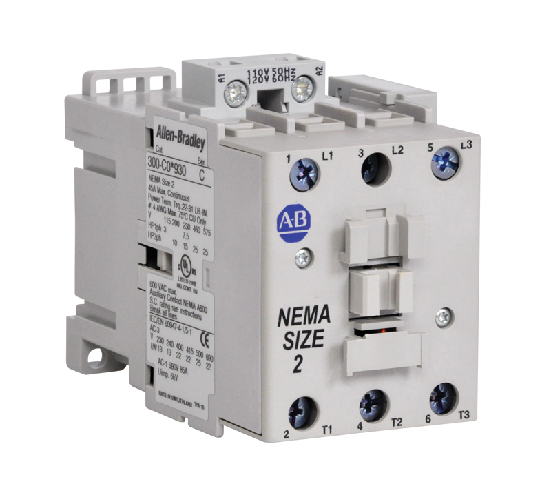
| NEMA size | Size 2 |
| Conductor size | 25 mm² |
| Main current circuit resistance | 0.21 mΩ, 3-pole |
| Rated isolation voltage (Ui) | 690V per IEC |
| Standard coil, pick-up | 25VA/25 W @ 48...130V AC/DC |
| Standard coil, hold-in | 4VA/2 W @ 48...130V AC/DC |
| General purpose current (enclosed) | 34A @ 600V per UL/CSA |
| Operating time, closing delay | 42...100 ms (Standard coil) |
| Power dissipation | 7 W per pole @ 400V, AC-1, Ie (3 pole) |
| Short time withstand (Icw) | 3-Poles: 600A @ 10s, 40 °C |
| Operating time, opening delay | 17...100 ms (Standard coil) |
| Rated operational current (enclosed) | 42 A @ 220-240V, 3-phase per UL/CSA |
| Rated operational power (enclosed) | 7.5Hp @ 240V, 1-phase per UL/CSA |
| Electromagnetic compatibility | IEC 60947-1 - Environment A |
| Total power dissipation | 10.1 W @ 400V, AC-3, Ie, AC/DC control (120-250V), 3 pole |
| Definite purpose rating | LRA: 360 A @ 440-480V AC (3-phase), UL/CSA HVAC applications |
| Operating limits, dropout | ≤0.60 x Us @ DC control |
| Insulation class of the coil | Class F per IEC 60947-4-1 |
| Operating limits, pick-up | (0.85...1.1) x Us @ 50/60 Hz |
| MCCB current rating | Type 2 (IEC 60947-4-1): 520A @ 400V, 70 kA available fault current |
| DIN fuses (gG) current rating | Type 2 (IEC 60947-4-1): 40A @ 690V, 60 kA available fault current |
| Rated voltage (Ue) | 24, 48, 110, 220, 440V DC |
| Hp rating, max | 25Hp @ 575V (60 Hz), 3-phase (Full-load current must not exceed continuous Aere) |
| Coil voltage | 24V 50/60 Hz |
| Switching of lighting loads | Tungsten lA, 3-phase (break all lines) (UL/CSA): 65A @ 600V |
| UL class RK5 fuses rating | Type 1 combination (UL60947 and CSA 22.2 No.14): 150A @ 600V, 5 kA available fault current |
| Rated operational current (Ie) | 70A @ 690V, AC-1 (50/60 Hz), ambient temperature 40 °C |
| UL class J and CSA HRCI-J fuses rating | Type 1 combination (UL60947 and CSA 22.2 No.14): 150A @ 600V, 100 kA available fault current |
| UL inverse-time circuit breaker | Type 1 combination (UL60947 and CSA 22.2 No.14): 250A @ 600V, 5 kA available fault current |
| Switching of power transformers | Apparent power: 87 kVA @ 600V, AC-6a @ 60Hz (n = 15) |
| Rated operational power (Pe) | 84 kW @ 690V, AC-1 (50/60 Hz), ambient temperature 40 °C |
| Switching of DC loads | 3-Poles in series: 70A @ 220V (Shunt-wound Motors-Starting, reverse current breaking, reversing, stepping DC-3 at 60 °C) |
| Number of power poles | Three pole + 1 NO auxiliary hold-in contact |
| Width | 2.48 mm |
|---|---|
| Height | 3.19 mm |
| Depth | 4.17 mm |
| Enclosure | Open Type |
| Lug | No built-in lug |
| Climatic withstand | Category B according to IEC 60947-1, Annex Q |
|---|---|
| Ambient temperature | Storage: -60...80 °C (-76...176 °F) |
| Altitude, max | 3000 m |
| Drawings | |
|---|---|
| 3D STEP Model (STP) | Download (ZIP) |
| Dimensions Drawing (PDF) | Download (PDF) |
| Product Drawing | Drawing (DXF) |
| Drawings |
|---|
| 3D STEP Model (STP) Download (ZIP) |
| Dimensions Drawing (PDF) Download (PDF) |
| Product Drawing Drawing (DXF) |
| Type | Resource | Publication |
|---|---|---|
| General | Product Cutsheet | -- |
| General | Circuit Protection Design and SCCR Tables | -- |
| General | Specification Sheet | -- |
| Technical Data | 300-td003_-en-p | 300-TD003 |
Looking for more documentation?
Find curated technical documentation for this product in the Technical Documentation Center, or search our full Literature Library.
Search the Literature Library
- Safety
This product was certified with the above certifications as of 2025-09-09. Products sold before or after this date might carry different certifications. Please review the product label to check for the certifications your specific product carries.
Looking for more Technotes?
Find questions and answers from Rockwell Automation technical experts for this product in our Knowledgebase.
Search Knowledgebase
Technical Specifications
| Enclosure Type | Open Style |
|---|
| Number of auxiliary contacts as normally open contact | 1 |
|---|---|
| Vibration resistance | IEC 60068-2-6 |
| Shock resistance | IEC 60068-2-27 |
| Switching frequency, max | 600 cycles/h, AC-1 |
| Recommended torque | Main contacts: 4 Nm |
| Weight | AC/DC (Electronic): 0.98 kg (2.16 lbs.) |
| Conductor cross section | Main contacts, 2 conductor: 6...35 mm² |
| Protection class | Contactor main contacts: IP2X |
| Voltage type for actuating | AC |
|---|---|
| Rated control supply voltage at AC 50 Hz | 24 V |
| Rated control supply voltage at AC 60 Hz | 24 V |
| Type of electrical connection of main circuit | Screw connection |
| Rated impulse voltage withstand (Uimp) | 6 kV |
| NEMA size | Size 2 |
| Conductor size | 25 mm² |
| Main current circuit resistance | 0.21 mΩ, 3-pole |
| Rated isolation voltage (Ui) | 690V per IEC |
| Standard coil, pick-up | 25VA/25 W @ 48...130V AC/DC |
| Standard coil, hold-in | 4VA/2 W @ 48...130V AC/DC |
| General purpose current (enclosed) | 34A @ 600V per UL/CSA |
| Operating time, closing delay | 42...100 ms (Standard coil) |
| Power dissipation | 7 W per pole @ 400V, AC-1, Ie (3 pole) |
| Short time withstand (Icw) | 3-Poles: 600A @ 10s, 40 °C |
| Operating time, opening delay | 17...100 ms (Standard coil) |
| Rated operational current (enclosed) | 42 A @ 220-240V, 3-phase per UL/CSA |
| Rated operational power (enclosed) | 7.5Hp @ 240V, 1-phase per UL/CSA |
| Electromagnetic compatibility | IEC 60947-1 - Environment A |
| Total power dissipation | 10.1 W @ 400V, AC-3, Ie, AC/DC control (120-250V), 3 pole |
| Definite purpose rating | LRA: 360 A @ 440-480V AC (3-phase), UL/CSA HVAC applications |
| Operating limits, dropout | ≤0.60 x Us @ DC control |
| Insulation class of the coil | Class F per IEC 60947-4-1 |
| Operating limits, pick-up | (0.85...1.1) x Us @ 50/60 Hz |
| MCCB current rating | Type 2 (IEC 60947-4-1): 520A @ 400V, 70 kA available fault current |
| DIN fuses (gG) current rating | Type 2 (IEC 60947-4-1): 40A @ 690V, 60 kA available fault current |
| Rated voltage (Ue) | 24, 48, 110, 220, 440V DC |
| Hp rating, max | 25Hp @ 575V (60 Hz), 3-phase (Full-load current must not exceed continuous Aere) |
| Coil voltage | 24V 50/60 Hz |
| Switching of lighting loads | Tungsten lA, 3-phase (break all lines) (UL/CSA): 65A @ 600V |
| UL class RK5 fuses rating | Type 1 combination (UL60947 and CSA 22.2 No.14): 150A @ 600V, 5 kA available fault current |
| Rated operational current (Ie) | 70A @ 690V, AC-1 (50/60 Hz), ambient temperature 40 °C |
| UL class J and CSA HRCI-J fuses rating | Type 1 combination (UL60947 and CSA 22.2 No.14): 150A @ 600V, 100 kA available fault current |
| UL inverse-time circuit breaker | Type 1 combination (UL60947 and CSA 22.2 No.14): 250A @ 600V, 5 kA available fault current |
| Switching of power transformers | Apparent power: 87 kVA @ 600V, AC-6a @ 60Hz (n = 15) |
| Rated operational power (Pe) | 84 kW @ 690V, AC-1 (50/60 Hz), ambient temperature 40 °C |
| Switching of DC loads | 3-Poles in series: 70A @ 220V (Shunt-wound Motors-Starting, reverse current breaking, reversing, stepping DC-3 at 60 °C) |
| Number of power poles | Three pole + 1 NO auxiliary hold-in contact |
| Width | 2.48 mm |
|---|---|
| Height | 3.19 mm |
| Depth | 4.17 mm |
| Enclosure | Open Type |
| Lug | No built-in lug |
| Climatic withstand | Category B according to IEC 60947-1, Annex Q |
|---|---|
| Ambient temperature | Storage: -60...80 °C (-76...176 °F) |
| Altitude, max | 3000 m |
Drawings
| Drawings | |
|---|---|
| 3D STEP Model (STP) | Download (ZIP) |
| Dimensions Drawing (PDF) | Download (PDF) |
| Product Drawing | Drawing (DXF) |
| Drawings |
|---|
| 3D STEP Model (STP) Download (ZIP) |
| Dimensions Drawing (PDF) Download (PDF) |
| Product Drawing Drawing (DXF) |
Documents
|
Product Cutsheet
General
-- |
|
Circuit Protection Design and SCCR Tables
General
-- |
|
Specification Sheet
General
-- |
|
300-td003_-en-p
Technical Data
300-TD003 |
| Type | Resource | Publication |
|---|---|---|
| General | Product Cutsheet | -- |
| General | Circuit Protection Design and SCCR Tables | -- |
| General | Specification Sheet | -- |
| Technical Data | 300-td003_-en-p | 300-TD003 |
Looking for more documentation?
Find curated technical documentation for this product in the Technical Documentation Center, or search our full Literature Library.
Search the Literature Library
Certifications
- Safety
This product was certified with the above certifications as of 2025-09-09. Products sold before or after this date might carry different certifications. Please review the product label to check for the certifications your specific product carries.
Accessories
Technotes
Looking for more Technotes?
Find questions and answers from Rockwell Automation technical experts for this product in our Knowledgebase.
Search Knowledgebase
Loading
Copyright ©2025 Rockwell Automation, Inc.