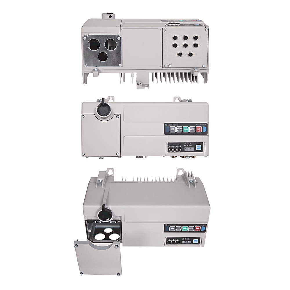
Variable Frequency Drive
Variable Frequency Drive
| Unique Product Identifier |
294E-FD2P5P-G3
|
|---|---|
| UPC |
885630827476
|
| Estimated Lead Time |
52 days
|
| Standard Warranty Duration |
1 year See details |
| Country of Origin |
Mexico
|
| Acceleration/deceleration |
Power circuit: two independently progmable acceleration and deceleration times. Each time can be progmed from 0...600 s in 0.1 s increments.
|
|---|---|
| Address conflict detection (ACD) |
IP v4 address conflict detection for EtherNet/IP devices
|
| Application |
Power circuit: three-phase
|
| Application in industrial area permitted |
True
|
| Carrier frequency |
Power circuit: 2...10 kHz, drive rating based on 4 kHz
|
| Class 1 connection API |
Network connections: 2...3200 ms
|
| Class 3 connection API |
Network connections: 100...10000 ms
|
| Concurrent TCP connections |
Network connections: maximum of 5 encapsulated messages over both TCP and UDP
|
| Concurrent explicit messages, max (CIP Class 3) |
Network connections: 6
|
| Concurrent sessions |
Web server: 20
|
| Consume instance (command) |
Default of 4 words (instance 154)
|
| Control ride through |
Power circuit: minimum ride through is 0.5 s - typical value is 2 s
|
| Control voltage |
Internal power supply
|
| Current, max |
Control circuit (external source): 450 mA @ unswitched power supply requirements
|
| Current, nom |
Control circuit (external source): 275 mA @ switched and unswitched power supply requirements
|
| DHCP timeout |
30 s
|
| Data |
Transported over both TCP and UDP
|
| Device level ring support |
Beacon performance, IEEE 1588 transparent clock
|
| DeviceLogix I/O response |
Input ratings: 2 ms @ 500 Hz
|
| Dielectric withstand |
Power circuit: 2500V AC per IEC
|
|
Web server: support simple mail transfer protocol (SMTP)
|
|
| Efficiency |
Power circuit: 97.5% typical
|
| EtherNet/IP ODVA – conformance testing |
EtherNet/IP interoperability performance - per A9 PF 2.1
|
| Ethernet cable |
Category 5e: shielded or unshielded
|
| Ethernet communication rate |
10/100 Mbps, half or full-duplex
|
| Ethernet connector |
M12, D code, female, with Ethernet keying, 4 pin
|
| Ethernet network topologies supported |
Star, tree, linear and ring
|
| Ethernet ports |
2 (embedded switch)
|
| Faultless power ride through |
Power circuit: 10 ms
|
| Fuse rating |
UL Class fuse (45 A, maximum)
|
| I/O connections, max (CIP Class 1) |
Network connections: supports up to 2 class 1 CIP connections [exclusive owner (data) or listen-only]. One connection per PLC. Listen only connection requires a data connection to be established.
|
| IP configuration |
Static, DHCP or BOOTP
|
| IPS option |
Control circuit (internal source): an internal 50 W power supply sources 24V DC for input, outputs and logic control (3-phase line power of 400Y/230V...480Y/277V @ 50/60Hz is required)
|
| Input OFF-state current |
<1.5 mA
|
| Input OFF-state voltage |
5V DC
|
| Input ON-state current (pin 4) |
2.6mA @ 24V DC
|
| Input ON-state voltage (pin 4), nom |
10...26.4V DC @ 24V DC
|
| Input bounce filter (software configurable) |
OFF-ON or ON-OFF: 0.5 ms + 64 ms
|
| Input connection type |
Single keyed M12, quick disconnect
|
| Input current (each) |
Control circuit (external source): 50 mA @ unswitched power supply requirements
|
| Input filtering |
100 µs
|
| Input per connection |
1/each
|
| Input power terminals |
Power circuit: L1, L2, L3
|
| Input supply voltage |
Unswitched power A3/A2
|
| Insulation voltage |
Rated 250V AC
|
| Insulation voltage (Ui) |
Output ratings: rated 2000V AC per IEC
|
| Mains frequency |
50/60 Hz
|
| Max. output frequency |
400 Hz
|
| Message support |
Unicast or multicast
|
| Motor cable length, max |
Power circuit: 10 m (32 ft)(CE application), Power circuit: 14 m (45.9 ft) (non-CE application)
|
| Motor control features |
Power circuit: flying start, V/F ratio, bus regulator, 4 preset speeds
|
| Motor control type |
Power circuit: slip compensation (Volts/Hz)
|
| Motor power terminals |
Power circuit: T1, T2, T3
|
| Number of input devices, max |
6
|
| Number of inputs (x 50 mA) |
Control circuit (external source): user defined @ switched and unswitched power supply requirements
|
| Number of outputs (x 500 mA) |
Control circuit (external source): user defined @ switched and unswitched power supply requirements
|
| Number of outputs, max |
6
|
| Operating dielectric withstand |
2000V AC per IEC
|
| Operating frequency |
Power circuit: 50/60 Hz (±10%)
|
| Output OFF-state leakage current, max |
1 µa
|
| Output blocking voltage, max |
35V DC
|
| Output connection type |
Single keyed M12, quick disconnect
|
| Output current (each) |
Control circuit (external source): 500 mA @ switched power supply requirements
|
| Output frequency |
Power circuit: 0...400 Hz progmable
|
| Output load types |
Resistive or light inductive
|
| Output operating current (Ie), nom |
500 mA per point
|
| Output overcurrent protection |
1.5 A (the sum of all outputs cannot exceed this value)
|
| Output per connection |
1/each
|
| Output state |
Normally open (NO)
|
| Output supply voltage (switched power) |
A1/A2
|
| Output surge suppression |
Integrated diode to help protect against switching loads
|
| Output thermal current (Ithe), max |
500 mA per point
|
| Output utilization category |
DC-1, DC-13 per IEC
|
| Over voltage |
Power circuit: 380...480V AC input - trip occurs at 810V DC bus voltage (equivalent to 575V AC incoming line)
|
| Overload type |
Power circuit: 150% @ 60s or 200% @ 3s @ solid-state I²t
|
| Overvoltage category |
Power circuit: III
|
| Overvoltage protection |
Control circuit (external source): reverse-polarity protected
|
| PE (earth ground) terminal |
Power circuit: 4 PE terminals
|
| Packet rate (pps) |
500 packets-per-s (2000 µs), Tx, 500 packets-per-s (2000 µs), Rx
|
| Peak inrush |
Control circuit (external source): <5 A for 35 ms @ unswitched power supply requirements
|
| Power |
Control circuit (external source): 6.6 W @ switched and unswitched power supply requirements
|
| Power supply |
Control circuit (external source): NEC Class 2
|
| Power, max |
Control circuit (external source): 6.6 W + (24V DC x user defined) @ switched and unswitched power supply requirements
|
| Produce instance (status) |
Default of 16 words (instance 156)
|
| RMS symmetrical amperes |
5 kA @ 480Y/277 (short circuit current rating)
|
| Rated impulse voltage (Uimp) |
Power circuit: 4 kV
|
| Rated input operation voltage |
24V DC
|
| Rated operating input current, max |
Power circuit: 3.7A @ 400V AC, 50 Hz, 1.0 Hp (0.75 kW)
|
| Rated operating voltage, max |
Power circuit: 400Y/230...480Y/277 (-15%, +10%)
|
| Rated output operating voltage (Ue) |
19.2...26.4V DC
|
| Request packet interval (RPI) |
Network connections: 20 ms default (2 ms minimum)
|
| Reset mode |
Power circuit: automatic/manual
|
| Security |
Web server: login and password configurable
|
| Sensor input leakage current, max |
<2.5 mA
|
| Sensor input operating voltage |
19.2...26V DC
|
| Sensor sourcing input current (pin 1), max |
50 mA per point (maximum 300 mA total for sourcing one device)
|
| Short circuit coordination |
Type 1
|
| Sockets, max |
150
|
| Source brake (EM brake) current |
Power circuit: maximum load current of 3 A
|
| Speed regulation - open loop with slip compensation |
Power circuit: ±2% of base speed across a 40:1 speed range
|
| Stop modes |
Power circuit: multiple progmable stop modes including, rA, coast, DC-brake, rA to hold, and S-curve
|
| Supporting protocol for EtherNet/IP |
True
|
| Trip class |
Power circuit: Class 10 protection with speed sensitive response and power-down overload retention function
|
| Trip rating |
Power circuit: 200% hardware limit, 300% instantaneous fault
|
| Type of inputs |
24V DC current sinking
|
| Type of outputs |
DC sourcing
|
| Under voltage |
Power circuit: 380...480V AC Input - trip occurs at 390V DC bus voltage (equivalent to 275V AC incoming line)
|
| Voltage |
Control circuit (external source): 19.2...26.4V DC @ unswitched power supply requirements
|
| Web server |
HTTP 1.1
|
| Webpage features |
Web server: status, diagnostics and configuration tabs
|
| Altitude |
1000 m
|
|---|---|
| Conducted emission |
EN 61800-3, C3
|
| Degree of protection (NEMA) |
4
|
| Electrostatic discharge |
4 kV contact and 8 kV air
|
| Fast transient |
2 kV (power), 2 kV (PE), 1 kV (communications and control)
|
| Humidity |
5...95% noncondensing
|
| Operating temperature |
-20...40 °C (-4...104 °F), up to 50 °C (122 °F) without derating, when properly rated line reactors are installed in branch circuit
|
| Pollution degree |
3
|
| Radiated emissions |
EN 61800-3, C3
|
| Radio frequency conducted disturbance immunity |
10V @ 150kHz...80 MHz
|
| Radio frequency electromagnetic field |
EN 55011 Class group 2, 10V/m, 80 MHz...1 GHz
|
| Storage and transportation temperature |
-25 °C
|
| Surge transient |
1 kV (12) L-L, 2 kV (2) L-N (earth)
|
| Depth |
202.27 mm
|
|---|---|
| Height |
219.32 mm
|
| Number of poles |
Power circuit: 3
|
| Width |
381 mm
|
| Wire size |
Source brake: #16 ... AWG (1.0...4.0 mm²) per terminal
|
| Degree of protection (IP) |
IP66
|
|---|---|
| Disconnect LOTO locks |
Up to 2 locks or hasps are supported
|
| Disconnect lock out |
Maximum of 3/8 in (9.5 mm) diam lock shackle or hasp
|
| Gland plate options |
Gland kits
|
| Mechanical life operations |
Disconnect: 200000
|
| Power rating |
Source brake: 10A @ 600V AC
|
| Shipping weight, approx |
7.3 kg
|
| Shock |
Opsal: 30 G, exceeds IEC 60947-1
|
| Tightening torque |
Source brake: 4.8 ± 2 in-lb (0.5 ± 0.2 Nm)
|
| Vibration |
Opsal: 2.5 G @ tested to MIL-STD-810G, exceeds IEC 60947-1
|
| Wire strip length |
0.35 ±0.01 in (9 ±2 mm)
|
| Wire type |
Multi-strand copper wire
|
| Drawings | |
|---|---|
| Dimensional Drawings (PDF) | Download (PDF) |
| 2D Drawings (DXF/DWG) | Download (ZIP) |
| Drawings |
|---|
| Dimensional Drawings (PDF) Download (PDF) |
| 2D Drawings (DXF/DWG) Download (ZIP) |
| General | Publication |
|---|---|
| Product Cutsheet | -- |
| Wiring Diagrams | -- |
| Specifications | -- |
| Circuit Protection Device And SCCR Tables | -- |
| Selection Guide | Publication |
|---|---|
| 280-sg002_-en-p | 280-SG002 |
| Technical Data | Publication |
|---|---|
| 290-td001_-en-p | 290-TD001 |
| User Manual | Publication |
|---|---|
| 290e-um001_-en-p | 290E-UM001 |
| AOP - Add On Profiles | Size | Notes | |
|---|---|---|---|
|
|
AOP - Add On Profiles for 294E v3.01.00 | 284 MB | Release notes |
|
|
AOP for 29xE v3.01.00 | 284 MB | Release notes |
| EDS - Electronic Data Sheet Files | Size | Notes | |
|
|
EDS files for 294E (multi) | 775 KB | |
|
|
EDS files for EtherNet/IP Family (multi) | 6.27 MB | |
|
|
EDS Files for 290x,291x, and 294x Series A and B v2.01 and prior | 775 KB | |
|
|
EDS Files for 290x,291x, and 294x Series A and B v2.01 and prior | 775 KB | |
|
|
EDS files for 294D (multi) | 266 KB | |
|
|
EDS files for DeviceNet Family (multi) | 7.66 MB | |
| Firmware | Size | Notes | |
|
|
Firmware for 294E v2.002 | 6.85 MB | Release notes |
|
|
Firmware for 294E v2.001 | 15.98 MB | Release notes |
|
|
Firmware for 290D, 291D, 294D v1.004 | 11.87 MB | Release notes |
| Product Security Advisory | Size | Notes | |
|
|
ArmorStart® LT - Multiple Denial-of-Service Vulnerabilities | - | |
|
|
ArmorStart® LT - Multiple Denial-of-Service Vulnerabilities | - | |

This product was certified with the above certifications as of 2026-08-02. Products sold before or after this date might carry different certifications. Please review the product label to check for the certifications your specific product carries.
Looking for certification documents?
Explore certifications for this product and more in our comprehensive Literature Library.
| EU Importer Address |
Rockwell Automation N.V |
|---|---|
| EU Authorized Representative Address |
Rockwell Automation N.V |
| Technotes |
|---|
Overview
| Unique Product Identifier |
294E-FD2P5P-G3
|
|---|---|
| UPC |
885630827476
|
| Estimated Lead Time |
52 days
|
| Standard Warranty Duration |
1 year See details |
| Country of Origin |
Mexico
|
Electrical & Connectivity
| Acceleration/deceleration |
Power circuit: two independently progmable acceleration and deceleration times. Each time can be progmed from 0...600 s in 0.1 s increments.
|
|---|---|
| Address conflict detection (ACD) |
IP v4 address conflict detection for EtherNet/IP devices
|
| Application |
Power circuit: three-phase
|
| Application in industrial area permitted |
True
|
| Carrier frequency |
Power circuit: 2...10 kHz, drive rating based on 4 kHz
|
| Class 1 connection API |
Network connections: 2...3200 ms
|
| Class 3 connection API |
Network connections: 100...10000 ms
|
| Concurrent TCP connections |
Network connections: maximum of 5 encapsulated messages over both TCP and UDP
|
| Concurrent explicit messages, max (CIP Class 3) |
Network connections: 6
|
| Concurrent sessions |
Web server: 20
|
| Consume instance (command) |
Default of 4 words (instance 154)
|
| Control ride through |
Power circuit: minimum ride through is 0.5 s - typical value is 2 s
|
| Control voltage |
Internal power supply
|
| Current, max |
Control circuit (external source): 450 mA @ unswitched power supply requirements
|
| Current, nom |
Control circuit (external source): 275 mA @ switched and unswitched power supply requirements
|
| DHCP timeout |
30 s
|
| Data |
Transported over both TCP and UDP
|
| Device level ring support |
Beacon performance, IEEE 1588 transparent clock
|
| DeviceLogix I/O response |
Input ratings: 2 ms @ 500 Hz
|
| Dielectric withstand |
Power circuit: 2500V AC per IEC
|
|
Web server: support simple mail transfer protocol (SMTP)
|
|
| Efficiency |
Power circuit: 97.5% typical
|
| EtherNet/IP ODVA – conformance testing |
EtherNet/IP interoperability performance - per A9 PF 2.1
|
| Ethernet cable |
Category 5e: shielded or unshielded
|
| Ethernet communication rate |
10/100 Mbps, half or full-duplex
|
| Ethernet connector |
M12, D code, female, with Ethernet keying, 4 pin
|
| Ethernet network topologies supported |
Star, tree, linear and ring
|
| Ethernet ports |
2 (embedded switch)
|
| Faultless power ride through |
Power circuit: 10 ms
|
| Fuse rating |
UL Class fuse (45 A, maximum)
|
| I/O connections, max (CIP Class 1) |
Network connections: supports up to 2 class 1 CIP connections [exclusive owner (data) or listen-only]. One connection per PLC. Listen only connection requires a data connection to be established.
|
| IP configuration |
Static, DHCP or BOOTP
|
| IPS option |
Control circuit (internal source): an internal 50 W power supply sources 24V DC for input, outputs and logic control (3-phase line power of 400Y/230V...480Y/277V @ 50/60Hz is required)
|
| Input OFF-state current |
<1.5 mA
|
| Input OFF-state voltage |
5V DC
|
| Input ON-state current (pin 4) |
2.6mA @ 24V DC
|
| Input ON-state voltage (pin 4), nom |
10...26.4V DC @ 24V DC
|
| Input bounce filter (software configurable) |
OFF-ON or ON-OFF: 0.5 ms + 64 ms
|
| Input connection type |
Single keyed M12, quick disconnect
|
| Input current (each) |
Control circuit (external source): 50 mA @ unswitched power supply requirements
|
| Input filtering |
100 µs
|
| Input per connection |
1/each
|
| Input power terminals |
Power circuit: L1, L2, L3
|
| Input supply voltage |
Unswitched power A3/A2
|
| Insulation voltage |
Rated 250V AC
|
| Insulation voltage (Ui) |
Output ratings: rated 2000V AC per IEC
|
| Mains frequency |
50/60 Hz
|
| Max. output frequency |
400 Hz
|
| Message support |
Unicast or multicast
|
| Motor cable length, max |
Power circuit: 10 m (32 ft)(CE application), Power circuit: 14 m (45.9 ft) (non-CE application)
|
| Motor control features |
Power circuit: flying start, V/F ratio, bus regulator, 4 preset speeds
|
| Motor control type |
Power circuit: slip compensation (Volts/Hz)
|
| Motor power terminals |
Power circuit: T1, T2, T3
|
| Number of input devices, max |
6
|
| Number of inputs (x 50 mA) |
Control circuit (external source): user defined @ switched and unswitched power supply requirements
|
| Number of outputs (x 500 mA) |
Control circuit (external source): user defined @ switched and unswitched power supply requirements
|
| Number of outputs, max |
6
|
| Operating dielectric withstand |
2000V AC per IEC
|
| Operating frequency |
Power circuit: 50/60 Hz (±10%)
|
| Output OFF-state leakage current, max |
1 µa
|
| Output blocking voltage, max |
35V DC
|
| Output connection type |
Single keyed M12, quick disconnect
|
| Output current (each) |
Control circuit (external source): 500 mA @ switched power supply requirements
|
| Output frequency |
Power circuit: 0...400 Hz progmable
|
| Output load types |
Resistive or light inductive
|
| Output operating current (Ie), nom |
500 mA per point
|
| Output overcurrent protection |
1.5 A (the sum of all outputs cannot exceed this value)
|
| Output per connection |
1/each
|
| Output state |
Normally open (NO)
|
| Output supply voltage (switched power) |
A1/A2
|
| Output surge suppression |
Integrated diode to help protect against switching loads
|
| Output thermal current (Ithe), max |
500 mA per point
|
| Output utilization category |
DC-1, DC-13 per IEC
|
| Over voltage |
Power circuit: 380...480V AC input - trip occurs at 810V DC bus voltage (equivalent to 575V AC incoming line)
|
| Overload type |
Power circuit: 150% @ 60s or 200% @ 3s @ solid-state I²t
|
| Overvoltage category |
Power circuit: III
|
| Overvoltage protection |
Control circuit (external source): reverse-polarity protected
|
| PE (earth ground) terminal |
Power circuit: 4 PE terminals
|
| Packet rate (pps) |
500 packets-per-s (2000 µs), Tx, 500 packets-per-s (2000 µs), Rx
|
| Peak inrush |
Control circuit (external source): <5 A for 35 ms @ unswitched power supply requirements
|
| Power |
Control circuit (external source): 6.6 W @ switched and unswitched power supply requirements
|
| Power supply |
Control circuit (external source): NEC Class 2
|
| Power, max |
Control circuit (external source): 6.6 W + (24V DC x user defined) @ switched and unswitched power supply requirements
|
| Produce instance (status) |
Default of 16 words (instance 156)
|
| RMS symmetrical amperes |
5 kA @ 480Y/277 (short circuit current rating)
|
| Rated impulse voltage (Uimp) |
Power circuit: 4 kV
|
| Rated input operation voltage |
24V DC
|
| Rated operating input current, max |
Power circuit: 3.7A @ 400V AC, 50 Hz, 1.0 Hp (0.75 kW)
|
| Rated operating voltage, max |
Power circuit: 400Y/230...480Y/277 (-15%, +10%)
|
| Rated output operating voltage (Ue) |
19.2...26.4V DC
|
| Request packet interval (RPI) |
Network connections: 20 ms default (2 ms minimum)
|
| Reset mode |
Power circuit: automatic/manual
|
| Security |
Web server: login and password configurable
|
| Sensor input leakage current, max |
<2.5 mA
|
| Sensor input operating voltage |
19.2...26V DC
|
| Sensor sourcing input current (pin 1), max |
50 mA per point (maximum 300 mA total for sourcing one device)
|
| Short circuit coordination |
Type 1
|
| Sockets, max |
150
|
| Source brake (EM brake) current |
Power circuit: maximum load current of 3 A
|
| Speed regulation - open loop with slip compensation |
Power circuit: ±2% of base speed across a 40:1 speed range
|
| Stop modes |
Power circuit: multiple progmable stop modes including, rA, coast, DC-brake, rA to hold, and S-curve
|
| Supporting protocol for EtherNet/IP |
True
|
| Trip class |
Power circuit: Class 10 protection with speed sensitive response and power-down overload retention function
|
| Trip rating |
Power circuit: 200% hardware limit, 300% instantaneous fault
|
| Type of inputs |
24V DC current sinking
|
| Type of outputs |
DC sourcing
|
| Under voltage |
Power circuit: 380...480V AC Input - trip occurs at 390V DC bus voltage (equivalent to 275V AC incoming line)
|
| Voltage |
Control circuit (external source): 19.2...26.4V DC @ unswitched power supply requirements
|
| Web server |
HTTP 1.1
|
| Webpage features |
Web server: status, diagnostics and configuration tabs
|
Compliance & Environment
| Altitude |
1000 m
|
|---|---|
| Conducted emission |
EN 61800-3, C3
|
| Degree of protection (NEMA) |
4
|
| Electrostatic discharge |
4 kV contact and 8 kV air
|
| Fast transient |
2 kV (power), 2 kV (PE), 1 kV (communications and control)
|
| Humidity |
5...95% noncondensing
|
| Operating temperature |
-20...40 °C (-4...104 °F), up to 50 °C (122 °F) without derating, when properly rated line reactors are installed in branch circuit
|
| Pollution degree |
3
|
| Radiated emissions |
EN 61800-3, C3
|
| Radio frequency conducted disturbance immunity |
10V @ 150kHz...80 MHz
|
| Radio frequency electromagnetic field |
EN 55011 Class group 2, 10V/m, 80 MHz...1 GHz
|
| Storage and transportation temperature |
-25 °C
|
| Surge transient |
1 kV (12) L-L, 2 kV (2) L-N (earth)
|
Physical Characteristics
| Depth |
202.27 mm
|
|---|---|
| Height |
219.32 mm
|
| Number of poles |
Power circuit: 3
|
| Width |
381 mm
|
| Wire size |
Source brake: #16 ... AWG (1.0...4.0 mm²) per terminal
|
| Degree of protection (IP) |
IP66
|
|---|---|
| Disconnect LOTO locks |
Up to 2 locks or hasps are supported
|
| Disconnect lock out |
Maximum of 3/8 in (9.5 mm) diam lock shackle or hasp
|
| Gland plate options |
Gland kits
|
| Mechanical life operations |
Disconnect: 200000
|
| Power rating |
Source brake: 10A @ 600V AC
|
| Shipping weight, approx |
7.3 kg
|
| Shock |
Opsal: 30 G, exceeds IEC 60947-1
|
| Tightening torque |
Source brake: 4.8 ± 2 in-lb (0.5 ± 0.2 Nm)
|
| Vibration |
Opsal: 2.5 G @ tested to MIL-STD-810G, exceeds IEC 60947-1
|
| Wire strip length |
0.35 ±0.01 in (9 ±2 mm)
|
| Wire type |
Multi-strand copper wire
|
Drawings
| Drawings | |
|---|---|
| Dimensional Drawings (PDF) | Download (PDF) |
| 2D Drawings (DXF/DWG) | Download (ZIP) |
| Drawings |
|---|
| Dimensional Drawings (PDF) Download (PDF) |
| 2D Drawings (DXF/DWG) Download (ZIP) |
Documents
|
Product Cutsheet
General
-- |
|
Wiring Diagrams
General
-- |
|
Specifications
General
-- |
|
Circuit Protection Device And SCCR Tables
General
-- |
|
280-sg002_-en-p
Selection Guide
280-SG002 |
|
290-td001_-en-p
Technical Data
290-TD001 |
|
290e-um001_-en-p
User Manual
290E-UM001 |
| General | Publication |
|---|---|
| Product Cutsheet | -- |
| Wiring Diagrams | -- |
| Specifications | -- |
| Circuit Protection Device And SCCR Tables | -- |
| Selection Guide | Publication |
| 280-sg002_-en-p | 280-SG002 |
| Technical Data | Publication |
| 290-td001_-en-p | 290-TD001 |
| User Manual | Publication |
| 290e-um001_-en-p | 290E-UM001 |
Downloads
| AOP - Add On Profiles | Size | Notes | |
|---|---|---|---|
|
|
AOP - Add On Profiles for 294E v3.01.00 | 284 MB | Release notes |
|
|
AOP for 29xE v3.01.00 | 284 MB | Release notes |
| EDS - Electronic Data Sheet Files | Size | Notes | |
|
|
EDS files for 294E (multi) | 775 KB | |
|
|
EDS files for EtherNet/IP Family (multi) | 6.27 MB | |
|
|
EDS Files for 290x,291x, and 294x Series A and B v2.01 and prior | 775 KB | |
|
|
EDS Files for 290x,291x, and 294x Series A and B v2.01 and prior | 775 KB | |
|
|
EDS files for 294D (multi) | 266 KB | |
|
|
EDS files for DeviceNet Family (multi) | 7.66 MB | |
| Firmware | Size | Notes | |
|
|
Firmware for 294E v2.002 | 6.85 MB | Release notes |
|
|
Firmware for 294E v2.001 | 15.98 MB | Release notes |
|
|
Firmware for 290D, 291D, 294D v1.004 | 11.87 MB | Release notes |
| Product Security Advisory | Size | Notes | |
|
|
ArmorStart® LT - Multiple Denial-of-Service Vulnerabilities | - | |
|
|
ArmorStart® LT - Multiple Denial-of-Service Vulnerabilities | - | |
Certifications
This product was certified with the above certifications as of 2026-08-02. Products sold before or after this date might carry different certifications. Please review the product label to check for the certifications your specific product carries.
Looking for certification documents?
Explore certifications for this product and more in our comprehensive Literature Library.
| EU Importer Address |
Rockwell Automation N.V |
|---|---|
| EU Authorized Representative Address |
Rockwell Automation N.V |
Accessories
Alternative Products
Technotes
| Technotes |
|---|
