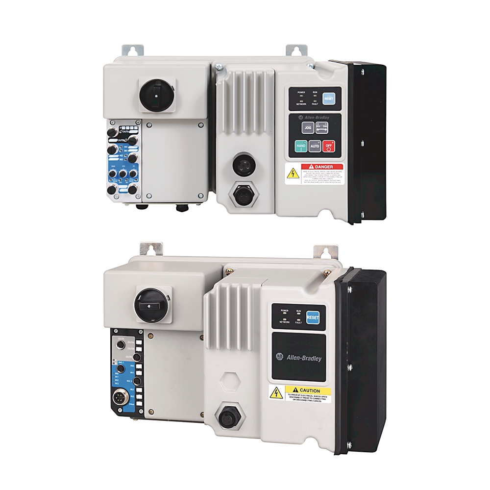
284e-fvd6p0z-25-cr-3-emi
EtherNet_IP ArmorStart VFD
Serial #:
This product has not been verified. Please register your product to confirm authenticity.
Lifecycle status:
Discontinued
Rockwell Automation announces that as of December 01, 2025, the EtherNet_IP ArmorStart VFD will be discontinued and no longer available for sale. Customers are encouraged to remove references to the affected product(s)
Discontinued Date:
December 01, 2025
Replacement Category:
Engineering Replacement
Product at a glance
Lifecycle status:
Discontinued
Rockwell Automation announces that as of December 01, 2025, the EtherNet_IP ArmorStart VFD will be discontinued and no longer available for sale. Customers are encouraged to remove references to the affected product(s)
Discontinued Date:
December 01, 2025
Replacement Category:
Engineering Replacement
Product at a glance
Description
Bulletin 284 ArmorStart W/ Variable Frequency AC DriveEtherNet/IP, 6.0A, 2.2kW, 3.0 Hp, 25 A Rated Device, Conduit Entrance with Motor Cable Supplied, Hand-Off-Auto Selector Keypad with Jog Function , EMI Filter
Overview
Technical Specifications
Mechanical
Environmental
Electrical
Construction
Drawings
Documents
Accessories
Alternative Products
Technotes
| Unique Product Identifier |
284e-fvd6p0z-25-cr-3-emi
|
|---|---|
| UPC |
885630255033
|
| Estimated Lead Time |
63 days
|
| Country of Origin |
Mexico
|
| Degree of protection (IP) |
IP67
|
|---|---|
| Shock |
Opsal: 15 G
|
| Wire strip length |
Power and ground terminals: 9 mm (0.35 in)
|
| Vibration |
Opsal, 1 G, 0.15 mm (0.006 in) displacement
|
| Tightening torque |
Power and ground terminals: 4.5 in-lb per UL/NEMA (sary terminal)
|
| Disconnect lock out |
Recommend 8 mm (5/16 in) lock shackle or hasp. The hasp should not exceed 8 mm (5/16 in) when closed.
|
| Approximate shipping weight |
19.1 kg
|
| Altitude |
1000 m
|
|---|---|
| Operating temperature |
-20 °C
|
| Storage and transportation temperature |
-25 °C
|
| Humidity |
5...95% on-condensing
|
| Protection against shock |
Power circuit: IP2X per IEC
|
| Surge transient |
1 kV L-L, 2 kV L-N (earth)
|
| Radiated emissions |
Class A, group 1, equivalent to C2 emissions
|
| Conducted radio frequency emissions |
Class A
|
| Radio frequency electromagnetic field |
10 V/m
|
| Degree of protection (NEMA) |
4
|
| Pollution degree |
3
|
| Fast transient |
2 kV
|
| Electrostatic discharge |
4 kV contact and 8 kV air
|
| Communication |
EtherNet/IP
|
|---|---|
| Short circuit protection |
25 A rated device
|
| Option 3 |
EMI filter
|
| DeviceNet input current surge |
15 A for 250 µs
|
| DeviceNet input current |
364mA @ 11V DC - 4.0 W
|
| Total w/max. sensor inputs (4) |
367mA @ 24V DC - 8.0 W
|
| Overvoltage category |
Control circuit: III per IEC
|
| Product type |
AC Drive
|
| Rated impulse voltage |
Power circuit: rated 6 kV
|
| DeviceNet supply voltage rating |
Range 11...25V DC @ 24V DC Nominal
|
| Baud rates |
125, 250, 500 kbps
|
| Rated input operation voltage |
24V DC
|
| Input OFF-state current |
<1.5 mA
|
| Rated output operating current, max |
Power circuit: 6 A @ 3-phase, 3 Hp rating
|
| Input OFF-state voltage |
0...5V DC
|
| Input ON-state voltage |
10...26V DC
|
| Torque performance mode |
Sensorless vector control and volts per Hz
|
| Distance, max |
500 m (1630 ft) @ 125 kbps
|
| Operating frequency |
Power circuit: 50/60 Hz
|
| Input ON-state current |
7.2mA @ 24V DC
|
| Option 1 |
HAND-OFF-AUTO selector keypad with jog function
|
| Number of contacts |
Output rating- sourced from control circuit: 2
|
| Short-circuit protection device list |
Size per NEC group motor per UL/NEMA
|
| Input compatibility |
IEC 1133 Type 1+
|
| Application in industrial area permitted (SCPD list) |
Size per NFPA 70 (NEC) or NFPA 79 for group motor applications
|
| Rated output operation voltage |
Sourced from control circuit: 240V AC / 30V DC
|
| Drive input current ratings |
9.00A @ 380V, 2.2 kW, 3-phase, 50 Hz
|
| Insulation voltage |
Power circuit: rated 600V AC
|
| Dielectric withstand |
Power circuit: 2500V AC per IEC
|
| Type of contacts |
Output rating- sourced from control circuit: normally open (NO)
|
| Outputs current (2) 1 A each, max |
External devices powered by control voltage: 2 A @ with brake and output contactor
|
| Current available |
Sensor source: 50 mA maximum per input, 200 mA total
|
| Type of control circuit |
Output rating- sourced from control circuit: electromechanical relay
|
| Conventional thermal current (Ith) |
Output rating- sourced from control circuit: total of both outputs ≤2 A
|
| RMS symmetrical amperes |
30 kA @ 600Y/347V per IEC
|
| Rated operation voltage |
Power circuit: 380Y/220...480Y/277V AC
|
| 3-phase power/motor cable connection |
Conduit entrance with motor cable
|
| Input filter - software selectable |
ON to OFF: settable from 0…64 ms in 1 ms increments
|
| Kind of current |
Output rating- sourced from control circuit: AC/DC
|
| Nominal control power (pick up) |
External devices powered by control voltage: 64 W @ with maximum outputs, with brake and output contactor
|
| Nominal control power (hold in) |
External devices powered by control voltage: 64 W @ with maximum outputs, with brake and output contactor
|
| Trip class |
Class 10
|
| Number of digital inputs |
4
|
| Number of digital outputs |
2
|
| Number of analogue inputs |
4
|
| Max. output frequency |
400 Hz
|
| Supporting protocol for EtherNet/IP |
True
|
| Mains frequency |
50/60 Hz
|
| Number of inputs |
4
|
| Enclosure type |
IP67/NEMA 4
|
| Disconnect |
Motor disconnect
|
| Connection type |
Quick disconnects
|
| Utilization category |
Power circuit: AC-3 per IEC
|
| External devices powered by DeviceNet |
50 mA - total 200 mA
|
| Voltage status |
Sensor source: 11...25V DC from DeviceNet
|
| Overload protection |
I²t overload protection - 150% @ 60s, 200% @ 30s
|
| Height, approx |
287.5 mm @ 460V AC, conduit entrance, 3 Hp and above
|
|---|---|
| Depth, approx |
266.9 mm @ 460V AC, conduit entrance, 3 Hp and above
|
| Terminal wire size |
Control and safety monitor inputs: 1.0...4.0 mm² per IEC
|
| Wire size |
Power and ground terminals: 1.5...4.0 mm² per IEC (primary/sary terminal)
|
| Width, approx |
444.38 mm @ 460V AC, conduit entrance, 3 Hp and above
|
| Number of poles |
3
|
| Drawings | |
|---|---|
| 3D STP (STEP) Model | Download (ZIP) |
| Drawings |
|---|
| 3D STP (STEP) Model Download (ZIP) |
| General | Publication |
|---|---|
| Repair Parts List | -- |
| External Connections and OL Curves | -- |
| Specifications Sheet | -- |
| Product Cutsheet | -- |
| Circuit Protection Device And SCCR Tables | -- |
| User Manual | Publication |
|---|---|
| 280e-um001_-en-p | 280E-UM001 |
Looking for more documentation?
Find curated technical documentation for this product in the Technical Documentation Center, or search our full Literature Library.
Search the Literature Library
Items Per Page:
Items Per Page:
| Technotes |
|---|
Looking for more Technotes?
Find questions and answers from Rockwell Automation technical experts for this product in our Knowledgebase.
Search Knowledgebase
Overview
| Unique Product Identifier |
284e-fvd6p0z-25-cr-3-emi
|
|---|---|
| UPC |
885630255033
|
| Estimated Lead Time |
63 days
|
| Country of Origin |
Mexico
|
Technical Specifications
| Degree of protection (IP) |
IP67
|
|---|---|
| Shock |
Opsal: 15 G
|
| Wire strip length |
Power and ground terminals: 9 mm (0.35 in)
|
| Vibration |
Opsal, 1 G, 0.15 mm (0.006 in) displacement
|
| Tightening torque |
Power and ground terminals: 4.5 in-lb per UL/NEMA (sary terminal)
|
| Disconnect lock out |
Recommend 8 mm (5/16 in) lock shackle or hasp. The hasp should not exceed 8 mm (5/16 in) when closed.
|
| Approximate shipping weight |
19.1 kg
|
| Altitude |
1000 m
|
|---|---|
| Operating temperature |
-20 °C
|
| Storage and transportation temperature |
-25 °C
|
| Humidity |
5...95% on-condensing
|
| Protection against shock |
Power circuit: IP2X per IEC
|
| Surge transient |
1 kV L-L, 2 kV L-N (earth)
|
| Radiated emissions |
Class A, group 1, equivalent to C2 emissions
|
| Conducted radio frequency emissions |
Class A
|
| Radio frequency electromagnetic field |
10 V/m
|
| Degree of protection (NEMA) |
4
|
| Pollution degree |
3
|
| Fast transient |
2 kV
|
| Electrostatic discharge |
4 kV contact and 8 kV air
|
| Communication |
EtherNet/IP
|
|---|---|
| Short circuit protection |
25 A rated device
|
| Option 3 |
EMI filter
|
| DeviceNet input current surge |
15 A for 250 µs
|
| DeviceNet input current |
364mA @ 11V DC - 4.0 W
|
| Total w/max. sensor inputs (4) |
367mA @ 24V DC - 8.0 W
|
| Overvoltage category |
Control circuit: III per IEC
|
| Product type |
AC Drive
|
| Rated impulse voltage |
Power circuit: rated 6 kV
|
| DeviceNet supply voltage rating |
Range 11...25V DC @ 24V DC Nominal
|
| Baud rates |
125, 250, 500 kbps
|
| Rated input operation voltage |
24V DC
|
| Input OFF-state current |
<1.5 mA
|
| Rated output operating current, max |
Power circuit: 6 A @ 3-phase, 3 Hp rating
|
| Input OFF-state voltage |
0...5V DC
|
| Input ON-state voltage |
10...26V DC
|
| Torque performance mode |
Sensorless vector control and volts per Hz
|
| Distance, max |
500 m (1630 ft) @ 125 kbps
|
| Operating frequency |
Power circuit: 50/60 Hz
|
| Input ON-state current |
7.2mA @ 24V DC
|
| Option 1 |
HAND-OFF-AUTO selector keypad with jog function
|
| Number of contacts |
Output rating- sourced from control circuit: 2
|
| Short-circuit protection device list |
Size per NEC group motor per UL/NEMA
|
| Input compatibility |
IEC 1133 Type 1+
|
| Application in industrial area permitted (SCPD list) |
Size per NFPA 70 (NEC) or NFPA 79 for group motor applications
|
| Rated output operation voltage |
Sourced from control circuit: 240V AC / 30V DC
|
| Drive input current ratings |
9.00A @ 380V, 2.2 kW, 3-phase, 50 Hz
|
| Insulation voltage |
Power circuit: rated 600V AC
|
| Dielectric withstand |
Power circuit: 2500V AC per IEC
|
| Type of contacts |
Output rating- sourced from control circuit: normally open (NO)
|
| Outputs current (2) 1 A each, max |
External devices powered by control voltage: 2 A @ with brake and output contactor
|
| Current available |
Sensor source: 50 mA maximum per input, 200 mA total
|
| Type of control circuit |
Output rating- sourced from control circuit: electromechanical relay
|
| Conventional thermal current (Ith) |
Output rating- sourced from control circuit: total of both outputs ≤2 A
|
| RMS symmetrical amperes |
30 kA @ 600Y/347V per IEC
|
| Rated operation voltage |
Power circuit: 380Y/220...480Y/277V AC
|
| 3-phase power/motor cable connection |
Conduit entrance with motor cable
|
| Input filter - software selectable |
ON to OFF: settable from 0…64 ms in 1 ms increments
|
| Kind of current |
Output rating- sourced from control circuit: AC/DC
|
| Nominal control power (pick up) |
External devices powered by control voltage: 64 W @ with maximum outputs, with brake and output contactor
|
| Nominal control power (hold in) |
External devices powered by control voltage: 64 W @ with maximum outputs, with brake and output contactor
|
| Trip class |
Class 10
|
| Number of digital inputs |
4
|
| Number of digital outputs |
2
|
| Number of analogue inputs |
4
|
| Max. output frequency |
400 Hz
|
| Supporting protocol for EtherNet/IP |
True
|
| Mains frequency |
50/60 Hz
|
| Number of inputs |
4
|
| Enclosure type |
IP67/NEMA 4
|
| Disconnect |
Motor disconnect
|
| Connection type |
Quick disconnects
|
| Utilization category |
Power circuit: AC-3 per IEC
|
| External devices powered by DeviceNet |
50 mA - total 200 mA
|
| Voltage status |
Sensor source: 11...25V DC from DeviceNet
|
| Overload protection |
I²t overload protection - 150% @ 60s, 200% @ 30s
|
| Height, approx |
287.5 mm @ 460V AC, conduit entrance, 3 Hp and above
|
|---|---|
| Depth, approx |
266.9 mm @ 460V AC, conduit entrance, 3 Hp and above
|
| Terminal wire size |
Control and safety monitor inputs: 1.0...4.0 mm² per IEC
|
| Wire size |
Power and ground terminals: 1.5...4.0 mm² per IEC (primary/sary terminal)
|
| Width, approx |
444.38 mm @ 460V AC, conduit entrance, 3 Hp and above
|
| Number of poles |
3
|
Drawings
| Drawings | |
|---|---|
| 3D STP (STEP) Model | Download (ZIP) |
| Drawings |
|---|
| 3D STP (STEP) Model Download (ZIP) |
Documents
|
Repair Parts List
General
-- |
|
External Connections and OL Curves
General
-- |
|
Specifications Sheet
General
-- |
|
Product Cutsheet
General
-- |
|
Circuit Protection Device And SCCR Tables
General
-- |
|
280e-um001_-en-p
User Manual
280E-UM001 |
| General | Publication |
|---|---|
| Repair Parts List | -- |
| External Connections and OL Curves | -- |
| Specifications Sheet | -- |
| Product Cutsheet | -- |
| Circuit Protection Device And SCCR Tables | -- |
| User Manual | Publication |
| 280e-um001_-en-p | 280E-UM001 |
Looking for more documentation?
Find curated technical documentation for this product in the Technical Documentation Center, or search our full Literature Library.
Search the Literature Library
Accessories
Items Per Page:
Alternative Products
Items Per Page:
Technotes
| Technotes |
|---|
Looking for more Technotes?
Find questions and answers from Rockwell Automation technical experts for this product in our Knowledgebase.
Search Knowledgebase
EtherNet_IP ArmorStart VFD
284e-fvd6p0z-25-cr-3-emi
Close
Print

Copyright ©2026 Rockwell Automation, Inc.