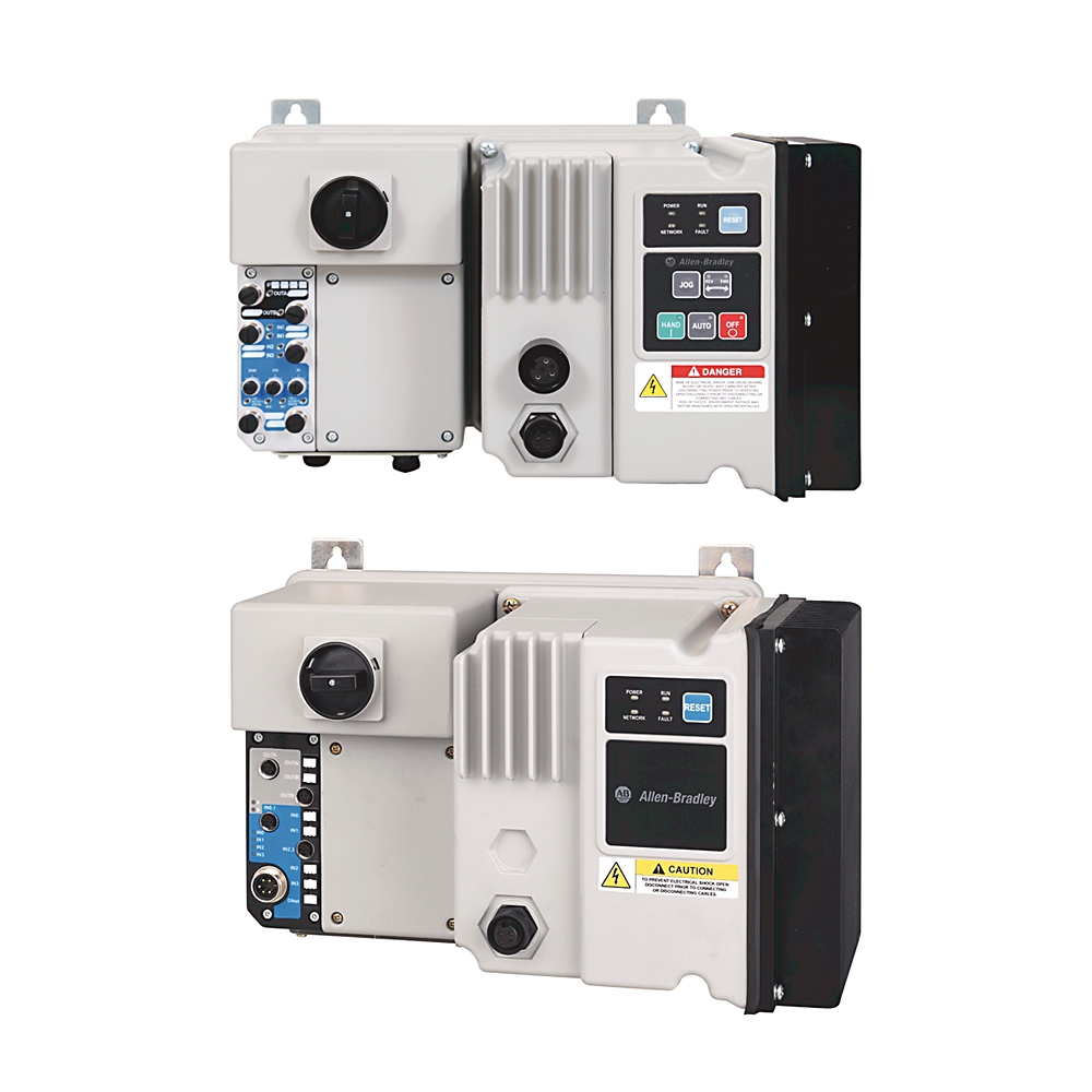
284E-FVD1P4Z-10-CRW-3-DB1-SBW
EtherNet_IP ArmorStart VFD
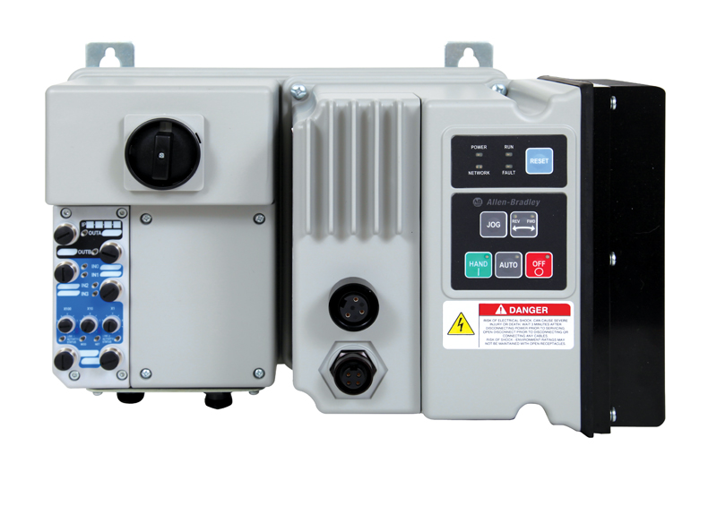
Product at a glance
Product at a glance
| Communications |
EtherNet
|
|---|---|
| Option 2 |
Source Brake Cntctr, No Cable
|
| Torque Performance Mode |
Sensorless Vect Ctrl and V/Hz
|
| Degree of protection (IP) |
IP67
|
|---|---|
| Shock |
Opsal: 15 G
|
| Wire strip length |
Power and ground terminals: 9 mm (0.35 in)
|
| Vibration |
Opsal, 1 G, 0.15 mm (0.006 in) displacement
|
| Tightening torque |
Power and ground terminals: 4.5 in-lb per UL/NEMA (sary terminal)
|
| Disconnect lock out |
Recommend 8 mm (5/16 in) lock shackle or hasp. The hasp should not exceed 8 mm (5/16 in) when closed.
|
| Approximate shipping weight |
19.1 kg
|
| Altitude |
1000 m
|
|---|---|
| Operating temperature |
-20 °C
|
| Storage and transportation temperature |
-25 °C
|
| Humidity |
5...95% on-condensing
|
| Protection against shock |
Power circuit: IP2X per IEC
|
| Surge transient |
1 kV L-L, 2 kV L-N (earth)
|
| Radiated emissions |
Class A, group 1, equivalent to C2 emissions
|
| Conducted radio frequency emissions |
Class A
|
| Radio frequency electromagnetic field |
10 V/m
|
| Degree of protection (NEMA) |
4
|
| Pollution degree |
3
|
| Fast transient |
2 kV
|
| Electrostatic discharge |
4 kV contact and 8 kV air
|
| Communication |
EtherNet/IP
|
|---|---|
| Short circuit protection |
10 A rated device
|
| DeviceNet input current surge |
15 A for 250 µs
|
| DeviceNet input current |
364mA @ 11V DC - 4.0 W
|
| Total w/max. sensor inputs (4) |
367mA @ 24V DC - 8.0 W
|
| Overvoltage category |
Control circuit: III per IEC
|
| Product type |
AC Drive
|
| Rated impulse voltage |
Power circuit: rated 6 kV
|
| DeviceNet supply voltage rating |
Range 11...25V DC @ 24V DC Nominal
|
| Baud rates |
125, 250, 500 kbps
|
| Rated input operation voltage |
24V DC
|
| Input OFF-state current |
<1.5 mA
|
| Rated output operating current, max |
Power circuit: 1.4 A @ 3-phase, 0.5 Hp rating
|
| Input OFF-state voltage |
0...5V DC
|
| Input ON-state voltage |
10...26V DC
|
| Torque performance mode |
Sensorless vector control and volts per Hz
|
| Distance, max |
500 m (1630 ft) @ 125 kbps
|
| Operating frequency |
Power circuit: 50/60 Hz
|
| Input ON-state current |
7.2mA @ 24V DC
|
| Option 1 |
HAND-OFF-AUTO selector keypad with jog function
|
| Number of contacts |
Output rating- sourced from control circuit: 2
|
| Short-circuit protection device list |
Size per NEC group motor per UL/NEMA
|
| Input compatibility |
IEC 1133 Type 1+
|
| Application in industrial area permitted (SCPD list) |
Size per NFPA 70 (NEC) or NFPA 79 for group motor applications
|
| Rated output operation voltage |
Sourced from control circuit: 240V AC / 30V DC
|
| Drive input current ratings |
2.15A @ 380V, 0.4 kW, 3-phase, 50 Hz
|
| Option 2 |
M25 source brake contactor connector, no cable
|
| Insulation voltage |
Power circuit: rated 600V AC
|
| Dielectric withstand |
Power circuit: 2500V AC per IEC
|
| Type of contacts |
Output rating- sourced from control circuit: normally open (NO)
|
| Outputs current (2) 1 A each, max |
External devices powered by control voltage: 2 A @ with brake and output contactor
|
| Current available |
Sensor source: 50 mA maximum per input, 200 mA total
|
| Type of control circuit |
Output rating- sourced from control circuit: electromechanical relay
|
| Conventional thermal current (Ith) |
Output rating- sourced from control circuit: total of both outputs ≤2 A
|
| RMS symmetrical amperes |
65kA @ 480V/277V per UL/NEMA
|
| Rated operation voltage |
Power circuit: 380Y/220...480Y/277V AC
|
| 3-phase power/motor cable connection |
Conduit entrance with no motor cable
|
| Input filter - software selectable |
ON to OFF: settable from 0…64 ms in 1 ms increments
|
| Kind of current |
Output rating- sourced from control circuit: AC/DC
|
| Nominal control power (pick up) |
External devices powered by control voltage: 64 W @ with maximum outputs, with brake and output contactor
|
| Nominal control power (hold in) |
External devices powered by control voltage: 64 W @ with maximum outputs, with brake and output contactor
|
| Trip class |
Class 10
|
| Number of digital inputs |
4
|
| Number of digital outputs |
2
|
| Number of analogue inputs |
4
|
| Max. output frequency |
400 Hz
|
| Supporting protocol for EtherNet/IP |
True
|
| Mains frequency |
50/60 Hz
|
| Number of inputs |
4
|
| Enclosure type |
IP67/NEMA 4
|
| Disconnect |
Motor disconnect
|
| Connection type |
Quick disconnects
|
| Utilization category |
Power circuit: AC-3 per IEC
|
| External devices powered by DeviceNet |
50 mA - total 200 mA
|
| Voltage status |
Sensor source: 11...25V DC from DeviceNet
|
| Overload protection |
I²t overload protection - 150% @ 60s, 200% @ 30s
|
| Height, approx |
287.5 mm @ 460V AC, conduit entrance, 2 Hp and below
|
|---|---|
| Depth, approx |
266.9 mm @ 460V AC, conduit entrance, 2 Hp and below
|
| Terminal wire size |
Control and safety monitor inputs: 1.0...4.0 mm² per IEC
|
| Wire size |
Power and ground terminals: 1.5...4.0 mm² per IEC (primary/sary terminal)
|
| Width, approx |
420.38 mm @ 460V AC, conduit entrance, 2 Hp and below
|
| Number of poles |
3
|
| Drawings | |
|---|---|
| 3D STP (STEP) Model | Download (ZIP) |
| Product Drawing | Drawing (DXF) |
| Drawings |
|---|
| 3D STP (STEP) Model Download (ZIP) |
| Product Drawing Drawing (DXF) |
| Type | Resource | Publication |
|---|---|---|
| General | Repair Parts List | -- |
| General | External Connections and OL Curves | -- |
| General | Specifications Sheet | -- |
| General | Circuit Protection Device And SCCR Tables | -- |
| General | Product Cutsheet | -- |
| User Manual | 280e-um001_-en-p | 280E-UM001 |
Looking for more documentation?
Find curated technical documentation for this product in the Technical Documentation Center, or search our full Literature Library.
Search the Literature Library
- CE
- Korean KC
- American Bureau of Shippin
- Safety
- UL Listed
- MOROCCO DOC
This product was certified with the above certifications as of 2025-09-10. Products sold before or after this date might carry different certifications. Please review the product label to check for the certifications your specific product carries.
Looking for more Technotes?
Find questions and answers from Rockwell Automation technical experts for this product in our Knowledgebase.
Search Knowledgebase
Technical Specifications
| Communications |
EtherNet
|
|---|---|
| Option 2 |
Source Brake Cntctr, No Cable
|
| Torque Performance Mode |
Sensorless Vect Ctrl and V/Hz
|
| Degree of protection (IP) |
IP67
|
|---|---|
| Shock |
Opsal: 15 G
|
| Wire strip length |
Power and ground terminals: 9 mm (0.35 in)
|
| Vibration |
Opsal, 1 G, 0.15 mm (0.006 in) displacement
|
| Tightening torque |
Power and ground terminals: 4.5 in-lb per UL/NEMA (sary terminal)
|
| Disconnect lock out |
Recommend 8 mm (5/16 in) lock shackle or hasp. The hasp should not exceed 8 mm (5/16 in) when closed.
|
| Approximate shipping weight |
19.1 kg
|
| Altitude |
1000 m
|
|---|---|
| Operating temperature |
-20 °C
|
| Storage and transportation temperature |
-25 °C
|
| Humidity |
5...95% on-condensing
|
| Protection against shock |
Power circuit: IP2X per IEC
|
| Surge transient |
1 kV L-L, 2 kV L-N (earth)
|
| Radiated emissions |
Class A, group 1, equivalent to C2 emissions
|
| Conducted radio frequency emissions |
Class A
|
| Radio frequency electromagnetic field |
10 V/m
|
| Degree of protection (NEMA) |
4
|
| Pollution degree |
3
|
| Fast transient |
2 kV
|
| Electrostatic discharge |
4 kV contact and 8 kV air
|
| Communication |
EtherNet/IP
|
|---|---|
| Short circuit protection |
10 A rated device
|
| DeviceNet input current surge |
15 A for 250 µs
|
| DeviceNet input current |
364mA @ 11V DC - 4.0 W
|
| Total w/max. sensor inputs (4) |
367mA @ 24V DC - 8.0 W
|
| Overvoltage category |
Control circuit: III per IEC
|
| Product type |
AC Drive
|
| Rated impulse voltage |
Power circuit: rated 6 kV
|
| DeviceNet supply voltage rating |
Range 11...25V DC @ 24V DC Nominal
|
| Baud rates |
125, 250, 500 kbps
|
| Rated input operation voltage |
24V DC
|
| Input OFF-state current |
<1.5 mA
|
| Rated output operating current, max |
Power circuit: 1.4 A @ 3-phase, 0.5 Hp rating
|
| Input OFF-state voltage |
0...5V DC
|
| Input ON-state voltage |
10...26V DC
|
| Torque performance mode |
Sensorless vector control and volts per Hz
|
| Distance, max |
500 m (1630 ft) @ 125 kbps
|
| Operating frequency |
Power circuit: 50/60 Hz
|
| Input ON-state current |
7.2mA @ 24V DC
|
| Option 1 |
HAND-OFF-AUTO selector keypad with jog function
|
| Number of contacts |
Output rating- sourced from control circuit: 2
|
| Short-circuit protection device list |
Size per NEC group motor per UL/NEMA
|
| Input compatibility |
IEC 1133 Type 1+
|
| Application in industrial area permitted (SCPD list) |
Size per NFPA 70 (NEC) or NFPA 79 for group motor applications
|
| Rated output operation voltage |
Sourced from control circuit: 240V AC / 30V DC
|
| Drive input current ratings |
2.15A @ 380V, 0.4 kW, 3-phase, 50 Hz
|
| Option 2 |
M25 source brake contactor connector, no cable
|
| Insulation voltage |
Power circuit: rated 600V AC
|
| Dielectric withstand |
Power circuit: 2500V AC per IEC
|
| Type of contacts |
Output rating- sourced from control circuit: normally open (NO)
|
| Outputs current (2) 1 A each, max |
External devices powered by control voltage: 2 A @ with brake and output contactor
|
| Current available |
Sensor source: 50 mA maximum per input, 200 mA total
|
| Type of control circuit |
Output rating- sourced from control circuit: electromechanical relay
|
| Conventional thermal current (Ith) |
Output rating- sourced from control circuit: total of both outputs ≤2 A
|
| RMS symmetrical amperes |
65kA @ 480V/277V per UL/NEMA
|
| Rated operation voltage |
Power circuit: 380Y/220...480Y/277V AC
|
| 3-phase power/motor cable connection |
Conduit entrance with no motor cable
|
| Input filter - software selectable |
ON to OFF: settable from 0…64 ms in 1 ms increments
|
| Kind of current |
Output rating- sourced from control circuit: AC/DC
|
| Nominal control power (pick up) |
External devices powered by control voltage: 64 W @ with maximum outputs, with brake and output contactor
|
| Nominal control power (hold in) |
External devices powered by control voltage: 64 W @ with maximum outputs, with brake and output contactor
|
| Trip class |
Class 10
|
| Number of digital inputs |
4
|
| Number of digital outputs |
2
|
| Number of analogue inputs |
4
|
| Max. output frequency |
400 Hz
|
| Supporting protocol for EtherNet/IP |
True
|
| Mains frequency |
50/60 Hz
|
| Number of inputs |
4
|
| Enclosure type |
IP67/NEMA 4
|
| Disconnect |
Motor disconnect
|
| Connection type |
Quick disconnects
|
| Utilization category |
Power circuit: AC-3 per IEC
|
| External devices powered by DeviceNet |
50 mA - total 200 mA
|
| Voltage status |
Sensor source: 11...25V DC from DeviceNet
|
| Overload protection |
I²t overload protection - 150% @ 60s, 200% @ 30s
|
| Height, approx |
287.5 mm @ 460V AC, conduit entrance, 2 Hp and below
|
|---|---|
| Depth, approx |
266.9 mm @ 460V AC, conduit entrance, 2 Hp and below
|
| Terminal wire size |
Control and safety monitor inputs: 1.0...4.0 mm² per IEC
|
| Wire size |
Power and ground terminals: 1.5...4.0 mm² per IEC (primary/sary terminal)
|
| Width, approx |
420.38 mm @ 460V AC, conduit entrance, 2 Hp and below
|
| Number of poles |
3
|
Drawings
| Drawings | |
|---|---|
| 3D STP (STEP) Model | Download (ZIP) |
| Product Drawing | Drawing (DXF) |
| Drawings |
|---|
| 3D STP (STEP) Model Download (ZIP) |
| Product Drawing Drawing (DXF) |
Documents
|
Repair Parts List
General
-- |
|
External Connections and OL Curves
General
-- |
|
Specifications Sheet
General
-- |
|
Circuit Protection Device And SCCR Tables
General
-- |
|
Product Cutsheet
General
-- |
|
280e-um001_-en-p
User Manual
280E-UM001 |
| Type | Resource | Publication |
|---|---|---|
| General | Repair Parts List | -- |
| General | External Connections and OL Curves | -- |
| General | Specifications Sheet | -- |
| General | Circuit Protection Device And SCCR Tables | -- |
| General | Product Cutsheet | -- |
| User Manual | 280e-um001_-en-p | 280E-UM001 |
Looking for more documentation?
Find curated technical documentation for this product in the Technical Documentation Center, or search our full Literature Library.
Search the Literature Library
Certifications
- CE
- Korean KC
- American Bureau of Shippin
- Safety
- UL Listed
- MOROCCO DOC
This product was certified with the above certifications as of 2025-09-10. Products sold before or after this date might carry different certifications. Please review the product label to check for the certifications your specific product carries.
Accessories
Alternative Products
Technotes
Looking for more Technotes?
Find questions and answers from Rockwell Automation technical experts for this product in our Knowledgebase.
Search Knowledgebase
Loading
Copyright ©2026 Rockwell Automation, Inc.