View all ArmorStart Distributed Motor Controllers
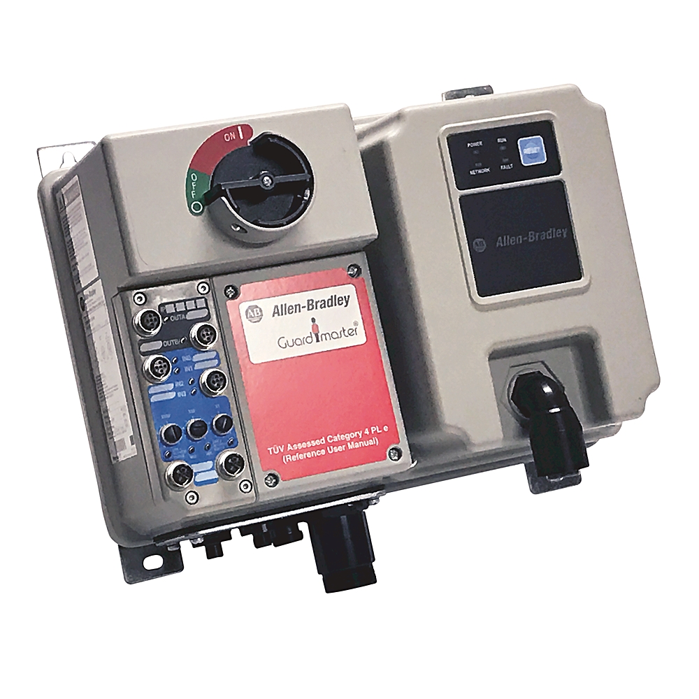
281E-F23S-25D-RRG
ArmorStart DOLR-G Saf Starter
Product at a glance
Product at a glance
| Communications |
EtherNet/IP
|
|---|---|
| Mounting |
Near motor
|
| Power Supply |
24V DC
|
| Setting |
Class 10,15,20
|
| Temperature Rating |
-20…40C
|
| Degree of protection (IP) |
IP67
|
|---|---|
| Shipping weight, approx |
10.4 kg
|
| Shock |
Opsal: 15 G
|
| Wire strip length |
Power and ground terminals: 0.35 in (9 mm)
|
| Vibration |
Opsal, 1 G, 0.15 mm (0.006 in) displacement
|
| Tightening torque |
Power and ground terminals: 4.5 in-lb per UL/NEMA (sary terminal)
|
| Mechanical life operations |
Contactor C23 (AC-3): 13000000 ops per IEC
|
| Disconnect lock out |
Recommend 8 mm (5/16 in) lock shackle or hasp. The hasp should not exceed 8 mm (5/16 in) when closed.
|
| Altitude |
2000 m
|
|---|---|
| Operating temperature |
-20 °C
|
| Storage and transportation temperature |
-25 °C
|
| Humidity |
5...95% (noncondensing)
|
| Protection against shock |
Power circuit: IP2X per IEC
|
| Surge transient |
1 kV (12) L-L, 2 kV (2) L-N (earth)
|
| Radiated emissions |
Class A, Group 1, equivalent to C2 emissions
|
| Conducted radio frequency emissions |
10V rms communications cables, 10V rms (PE), 150 kHz...80 MHz
|
| Radio frequency electromagnetic field |
10V/m, 80 MHz...1 GHz, 3V/m, 1.4 GHz...2 GHz, 1V/m, 2.0 GHz...2.7 GHz
|
| Degree of protection (NEMA) |
4
|
| Pollution degree |
3
|
| Electrostatic discharge |
4 kV contact and 8 kV Air
|
| Fast transient |
2 kV (power), 2 kV (PE), 1 kV (communications and control)
|
| Component response time |
20 ms
|
|---|---|
| Short circuit protection |
25 A rated device
|
| DHCP timeout |
Ethernet port: 30 s
|
| Web server |
Embedded web server
|
| Contactor size |
25 A safety contactor
|
| Safety |
Hardwired Safety (STO)
|
| Overvoltage category |
Control circuit: III per IEC
|
| Rated operational current |
Power circuit: 16 A maximum
|
| Product type |
Reversing starter
|
| Rated impulse voltage |
Power circuit: 6 kV
|
| IP address |
Ethernet port: DHCP enabled by default
|
| Average probability of dangerous failure |
MTTF for uncontrolled stop: 6.0E-9 (1/h)
|
| Ports |
Ethernet port: embedded switch with 2 ports
|
| Rated input operation voltage |
Sourced from control circuit (A3/A2): 24V DC
|
| Input OFF-state current |
Sourced from control circuit (A3/A3): <1.5 mA
|
| Input OFF-state voltage |
Sourced from control circuit (A3/A3): 0...5V DC
|
| Module inrush current |
EtherNet/IP version: 1.09 A (A1/A2 with HOA)
|
| Module steady current |
EtherNet/IP version: 0.3 A (A3/A2 without HOA)
|
| Total control power (running) |
EtherNet/IP version: 7.2 W (A3/A2 without HOA)
|
| Input ON-state voltage |
Sourced from control circuit (A3/A3): 10...26V DC
|
| Operating frequency |
Power circuit: 50/60 Hz
|
| Input ON-state current |
Sourced from control circuit (A3/A3): 7.2mA @ 24V DC
|
| Ethernet receptacles |
Ethernet port: 2 D-coded, 4-pin female M12 connectors
|
| Option 1 |
Status only keypad
|
| Number of contacts |
Output ratings - sourced from control circuit (A1/A2): 2
|
| Voltage status only |
Sensor source: 11...26.4V DC from unswitched power (A3-A2)
|
| Trip rating |
120% of full load current (FLC) setting
|
| Type of current |
Output ratings - sourced from control circuit (A1/A2): 24 DC
|
| Input compatibility |
Sourced from control circuit (A3/A3): IEC 61131-2 per IEC
|
| Application in industrial area permitted (SCPD list) |
Size per NFPA 70 (NEC) or NFPA 79 for group motor applications
|
| ON-state voltage, max |
Output ratings - sourced from control circuit (A1/A2): 1.5V DC
|
| Contact rating |
SI - SM1 and SM2 (24V DC): DC-12 L/R, 1 ms resistive, 6 A
|
| Rated output operation voltage |
Output ratings - sourced from control circuit (A1/A2): 26.4V DC
|
| Insulation voltage |
Power circuit: rated 600V
|
| Communication rate |
Ethernet port: 10/100 Mbs with auto negotiate half duplex and full duplex
|
| Dielectric withstand |
Power circuit: 2500V AC per IEC
|
| Type of contacts |
Output ratings - sourced from control circuit (A1/A2): normally open (N.O.)
|
| SO - P/M |
SI - SM1 and SM2 (24V DC): 3 W/0.125 A per contactor (two safety contactors)
|
| Current available |
Sensor source: 50 mA maximum per input, 200 mA for any single point
|
| Type of control circuit |
Output ratings - sourced from control circuit (A1/A2): solid state sourcing output
|
| Conventional thermal current (Ith) |
Output ratings - sourced from control circuit (A1/A2): 0.5 A each, 1 A maximum combined
|
| Circuit breaker operational current rating, max |
60 A @ 600Y/347V
|
| RMS symmetrical amperes |
65 kA @ 600Y/347V
|
| Rated operation voltage |
Power circuit: 200...575V
|
| 3-phase power/motor cable connection |
Control and 3-phase power, male receptacle with motor cable
|
| Input filter - software selectable |
Sourced from control circuit (A3/A3): settable from 0...64 ms in 1 ms increments (ON to OFF)
|
| Fuse operational current rating, max |
30 A @ 600Y/347V
|
| Total control power (pick up) |
EtherNet/IP version: 7.2 W (A3/A2 without HOA)
|
| Peak output current |
Output ratings - sourced from control circuit (A1/A2): current limited 2-8 A (5 A nominal) @ 24V DC
|
| Trip class |
Class 10, 15, 20
|
| Operational power rating |
Reversing starters - IP67/NEMA Type 4: 7.5 kW @ 400V AC @ 50Hz
|
| Data |
Ethernet port: Transported over both TCP and UDP, Minimum of 500 I/O packets/s (pps), Supports up to 150 concurrent TCP sockets
|
| Input frequency response, max |
Sourced from control circuit (A3/A3): 200 Hz (DeviceLogix response is greater than 200 Hz. Network response depends on control system network performance.)
|
| Device connections |
TCP port supports 5 concurrent incoming connections
|
| Number of digital inputs |
4
|
| Number of digital outputs |
2
|
| Application in industrial area permitted |
True
|
| Supporting protocol for EtherNet/IP |
True
|
| Mains frequency |
50/60 Hz
|
| MTTFd years |
100 year
|
| Short circuit protection device (SCPD) |
Type 1
|
| Short circuit rating |
30 kA
|
| Disconnect |
Motor disconnect
|
| Conection type |
Quick disconnects
|
| Utilization category |
Power circuit: AC-3 per IEC
|
| Security |
Web server: login and password configurable
|
| Configuration |
Web server: status, diagnostics and configuration tabs
|
|
Web server: support simple mail transfer protocol (SMTP)
|
|
| Off-state leakage current, max |
Output ratings - sourced from control circuit (A1/A2): 10 µA
|
| Blocking voltage, max |
Output ratings - sourced from control circuit (A1/A2): 35V DC
|
| Contact type |
SI - SM1 and SM2 (24V DC): IEC 60947-5-1 Annex L - mechanically
|
| Fault recovery |
DLR: ring recovery time is less than 3 ms for a 50 node network
|
| DC control voltage |
EtherNet/IP version: 24V DC (A1/A2, A3/A2, without and without HOA)
|
| Device level ring |
Beacon-based performance including IEEE 1588 end to end transparent clock
|
| Load types |
Output ratings - sourced from control circuit (A1/A2): resistive or light inductive
|
| Surge suppression |
Output ratings - sourced from control circuit (A1/A2): integrated diode, clA @ 35V DC
|
| Cycle rate, max |
Output ratings - sourced from control circuit (A1/A2): 30 ops/minute capacitive and inductive loads
|
| Thermo-protection |
Output ratings - sourced from control circuit (A1/A2): integrated short circuit and over current protection
|
| Height, approx |
287.5 mm
|
|---|---|
| Depth, approx |
256.2 mm
|
| Wire size |
Power and ground terminals: #16... AWG per UL/NEMA (primary/sary terminal)
|
| Width, approx |
373.555 mm
|
| Number of poles |
3
|
| Drawings | |
|---|---|
| Dimensional Drawing (PDF) | Download (PDF) |
| 3-Dimensional STEP model (STP) | Download (ZIP) |
| Drawings |
|---|
| Dimensional Drawing (PDF) Download (PDF) |
| 3-Dimensional STEP model (STP) Download (ZIP) |
| General | Publication |
|---|---|
| Product Profile | 280ES-PC001 |
| Selection Guide | 280-SG002 |
| User Manual | 280ES-UM002 |
| Product Cutsheet | -- |
| Technical Data | 280ES-TD001 |
| Selection Guide | Publication |
|---|---|
| 280-sg002_-en-p | 280-SG002 |
| User Manual | Publication |
|---|---|
| 280es-um002_-en-p | 280ES-UM002 |
Looking for more documentation?
Find curated technical documentation for this product in the Technical Documentation Center, or search our full Literature Library.
Visit the Technical Documentation Center
Search the Literature Library
| Technotes |
|---|
Looking for more Technotes?
Find questions and answers from Rockwell Automation technical experts for this product in our Knowledgebase.
Search Knowledgebase
Technical Specifications
| Communications |
EtherNet/IP
|
|---|---|
| Mounting |
Near motor
|
| Power Supply |
24V DC
|
| Setting |
Class 10,15,20
|
| Temperature Rating |
-20…40C
|
| Degree of protection (IP) |
IP67
|
|---|---|
| Shipping weight, approx |
10.4 kg
|
| Shock |
Opsal: 15 G
|
| Wire strip length |
Power and ground terminals: 0.35 in (9 mm)
|
| Vibration |
Opsal, 1 G, 0.15 mm (0.006 in) displacement
|
| Tightening torque |
Power and ground terminals: 4.5 in-lb per UL/NEMA (sary terminal)
|
| Mechanical life operations |
Contactor C23 (AC-3): 13000000 ops per IEC
|
| Disconnect lock out |
Recommend 8 mm (5/16 in) lock shackle or hasp. The hasp should not exceed 8 mm (5/16 in) when closed.
|
| Altitude |
2000 m
|
|---|---|
| Operating temperature |
-20 °C
|
| Storage and transportation temperature |
-25 °C
|
| Humidity |
5...95% (noncondensing)
|
| Protection against shock |
Power circuit: IP2X per IEC
|
| Surge transient |
1 kV (12) L-L, 2 kV (2) L-N (earth)
|
| Radiated emissions |
Class A, Group 1, equivalent to C2 emissions
|
| Conducted radio frequency emissions |
10V rms communications cables, 10V rms (PE), 150 kHz...80 MHz
|
| Radio frequency electromagnetic field |
10V/m, 80 MHz...1 GHz, 3V/m, 1.4 GHz...2 GHz, 1V/m, 2.0 GHz...2.7 GHz
|
| Degree of protection (NEMA) |
4
|
| Pollution degree |
3
|
| Electrostatic discharge |
4 kV contact and 8 kV Air
|
| Fast transient |
2 kV (power), 2 kV (PE), 1 kV (communications and control)
|
| Component response time |
20 ms
|
|---|---|
| Short circuit protection |
25 A rated device
|
| DHCP timeout |
Ethernet port: 30 s
|
| Web server |
Embedded web server
|
| Contactor size |
25 A safety contactor
|
| Safety |
Hardwired Safety (STO)
|
| Overvoltage category |
Control circuit: III per IEC
|
| Rated operational current |
Power circuit: 16 A maximum
|
| Product type |
Reversing starter
|
| Rated impulse voltage |
Power circuit: 6 kV
|
| IP address |
Ethernet port: DHCP enabled by default
|
| Average probability of dangerous failure |
MTTF for uncontrolled stop: 6.0E-9 (1/h)
|
| Ports |
Ethernet port: embedded switch with 2 ports
|
| Rated input operation voltage |
Sourced from control circuit (A3/A2): 24V DC
|
| Input OFF-state current |
Sourced from control circuit (A3/A3): <1.5 mA
|
| Input OFF-state voltage |
Sourced from control circuit (A3/A3): 0...5V DC
|
| Module inrush current |
EtherNet/IP version: 1.09 A (A1/A2 with HOA)
|
| Module steady current |
EtherNet/IP version: 0.3 A (A3/A2 without HOA)
|
| Total control power (running) |
EtherNet/IP version: 7.2 W (A3/A2 without HOA)
|
| Input ON-state voltage |
Sourced from control circuit (A3/A3): 10...26V DC
|
| Operating frequency |
Power circuit: 50/60 Hz
|
| Input ON-state current |
Sourced from control circuit (A3/A3): 7.2mA @ 24V DC
|
| Ethernet receptacles |
Ethernet port: 2 D-coded, 4-pin female M12 connectors
|
| Option 1 |
Status only keypad
|
| Number of contacts |
Output ratings - sourced from control circuit (A1/A2): 2
|
| Voltage status only |
Sensor source: 11...26.4V DC from unswitched power (A3-A2)
|
| Trip rating |
120% of full load current (FLC) setting
|
| Type of current |
Output ratings - sourced from control circuit (A1/A2): 24 DC
|
| Input compatibility |
Sourced from control circuit (A3/A3): IEC 61131-2 per IEC
|
| Application in industrial area permitted (SCPD list) |
Size per NFPA 70 (NEC) or NFPA 79 for group motor applications
|
| ON-state voltage, max |
Output ratings - sourced from control circuit (A1/A2): 1.5V DC
|
| Contact rating |
SI - SM1 and SM2 (24V DC): DC-12 L/R, 1 ms resistive, 6 A
|
| Rated output operation voltage |
Output ratings - sourced from control circuit (A1/A2): 26.4V DC
|
| Insulation voltage |
Power circuit: rated 600V
|
| Communication rate |
Ethernet port: 10/100 Mbs with auto negotiate half duplex and full duplex
|
| Dielectric withstand |
Power circuit: 2500V AC per IEC
|
| Type of contacts |
Output ratings - sourced from control circuit (A1/A2): normally open (N.O.)
|
| SO - P/M |
SI - SM1 and SM2 (24V DC): 3 W/0.125 A per contactor (two safety contactors)
|
| Current available |
Sensor source: 50 mA maximum per input, 200 mA for any single point
|
| Type of control circuit |
Output ratings - sourced from control circuit (A1/A2): solid state sourcing output
|
| Conventional thermal current (Ith) |
Output ratings - sourced from control circuit (A1/A2): 0.5 A each, 1 A maximum combined
|
| Circuit breaker operational current rating, max |
60 A @ 600Y/347V
|
| RMS symmetrical amperes |
65 kA @ 600Y/347V
|
| Rated operation voltage |
Power circuit: 200...575V
|
| 3-phase power/motor cable connection |
Control and 3-phase power, male receptacle with motor cable
|
| Input filter - software selectable |
Sourced from control circuit (A3/A3): settable from 0...64 ms in 1 ms increments (ON to OFF)
|
| Fuse operational current rating, max |
30 A @ 600Y/347V
|
| Total control power (pick up) |
EtherNet/IP version: 7.2 W (A3/A2 without HOA)
|
| Peak output current |
Output ratings - sourced from control circuit (A1/A2): current limited 2-8 A (5 A nominal) @ 24V DC
|
| Trip class |
Class 10, 15, 20
|
| Operational power rating |
Reversing starters - IP67/NEMA Type 4: 7.5 kW @ 400V AC @ 50Hz
|
| Data |
Ethernet port: Transported over both TCP and UDP, Minimum of 500 I/O packets/s (pps), Supports up to 150 concurrent TCP sockets
|
| Input frequency response, max |
Sourced from control circuit (A3/A3): 200 Hz (DeviceLogix response is greater than 200 Hz. Network response depends on control system network performance.)
|
| Device connections |
TCP port supports 5 concurrent incoming connections
|
| Number of digital inputs |
4
|
| Number of digital outputs |
2
|
| Application in industrial area permitted |
True
|
| Supporting protocol for EtherNet/IP |
True
|
| Mains frequency |
50/60 Hz
|
| MTTFd years |
100 year
|
| Short circuit protection device (SCPD) |
Type 1
|
| Short circuit rating |
30 kA
|
| Disconnect |
Motor disconnect
|
| Conection type |
Quick disconnects
|
| Utilization category |
Power circuit: AC-3 per IEC
|
| Security |
Web server: login and password configurable
|
| Configuration |
Web server: status, diagnostics and configuration tabs
|
|
Web server: support simple mail transfer protocol (SMTP)
|
|
| Off-state leakage current, max |
Output ratings - sourced from control circuit (A1/A2): 10 µA
|
| Blocking voltage, max |
Output ratings - sourced from control circuit (A1/A2): 35V DC
|
| Contact type |
SI - SM1 and SM2 (24V DC): IEC 60947-5-1 Annex L - mechanically
|
| Fault recovery |
DLR: ring recovery time is less than 3 ms for a 50 node network
|
| DC control voltage |
EtherNet/IP version: 24V DC (A1/A2, A3/A2, without and without HOA)
|
| Device level ring |
Beacon-based performance including IEEE 1588 end to end transparent clock
|
| Load types |
Output ratings - sourced from control circuit (A1/A2): resistive or light inductive
|
| Surge suppression |
Output ratings - sourced from control circuit (A1/A2): integrated diode, clA @ 35V DC
|
| Cycle rate, max |
Output ratings - sourced from control circuit (A1/A2): 30 ops/minute capacitive and inductive loads
|
| Thermo-protection |
Output ratings - sourced from control circuit (A1/A2): integrated short circuit and over current protection
|
| Height, approx |
287.5 mm
|
|---|---|
| Depth, approx |
256.2 mm
|
| Wire size |
Power and ground terminals: #16... AWG per UL/NEMA (primary/sary terminal)
|
| Width, approx |
373.555 mm
|
| Number of poles |
3
|
Drawings
| Drawings | |
|---|---|
| Dimensional Drawing (PDF) | Download (PDF) |
| 3-Dimensional STEP model (STP) | Download (ZIP) |
| Drawings |
|---|
| Dimensional Drawing (PDF) Download (PDF) |
| 3-Dimensional STEP model (STP) Download (ZIP) |
Documents
|
Product Profile
General
280ES-PC001 |
|
Selection Guide
General
280-SG002 |
|
User Manual
General
280ES-UM002 |
|
Product Cutsheet
General
-- |
|
Technical Data
General
280ES-TD001 |
|
280-sg002_-en-p
Selection Guide
280-SG002 |
|
280es-um002_-en-p
User Manual
280ES-UM002 |
| General | Publication |
|---|---|
| Product Profile | 280ES-PC001 |
| Selection Guide | 280-SG002 |
| User Manual | 280ES-UM002 |
| Product Cutsheet | -- |
| Technical Data | 280ES-TD001 |
| Selection Guide | Publication |
| 280-sg002_-en-p | 280-SG002 |
| User Manual | Publication |
| 280es-um002_-en-p | 280ES-UM002 |
Looking for more documentation?
Find curated technical documentation for this product in the Technical Documentation Center, or search our full Literature Library.
Visit the Technical Documentation Center
Search the Literature Library
Accessories
Alternative Products
Technotes
| Technotes |
|---|
Looking for more Technotes?
Find questions and answers from Rockwell Automation technical experts for this product in our Knowledgebase.
Search Knowledgebase
Copyright ©2026 Rockwell Automation, Inc.