View all ArmorStart Distributed Motor Controllers
280E-FN-10-C
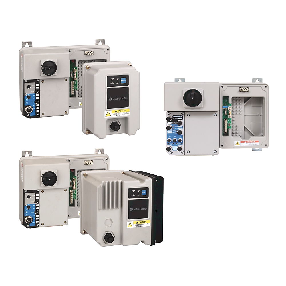
ArmorStart Repair Base Mod Starter
Product at a glance
Product at a glance
| Communications |
Ethernet
|
|---|
| Degree of protection (IP) |
IP67
|
|---|---|
| Shipping weight, approx |
10.4 kg
|
| Shock |
Opsal: 15 G
|
| Wire strip length |
Power and ground terminals: 0.35 in (9 mm)
|
| Vibration |
Opsal, 1 G, 0.15 mm (0.006 in) displacement
|
| Tightening torque |
Power and ground terminals: 4.5 in-lb per UL/NEMA (sary terminal)
|
| Mechanical life operations |
Contactor C23 (AC-3): 13000000 ops per IEC
|
| Disconnect lock out |
Recommend 8 mm (5/16 in) lock shackle or hasp. The hasp should not exceed 8 mm (5/16 in) when closed.
|
| Altitude |
2000 m
|
|---|---|
| Operating temperature |
-20 °C
|
| Storage and transportation temperature |
-25 °C
|
| Humidity |
5...95% (noncondensing)
|
| Protection against shock |
Power circuit: IP2X per IEC
|
| Surge transient |
1 kV (12) L-L, 2 kV (2) L-N (earth)
|
| Radiated emissions |
Class A, Group 1, equivalent to C2 emissions
|
| Conducted radio frequency emissions |
10V rms communications cables, 10V rms (PE), 150 kHz...80 MHz
|
| Radio frequency electromagnetic field |
10V/m, 80 KHz...1 GHz, 3V/m, 1.4 GHz...2 GHz, 1V/m, 2.0 GHz ...2.7 GHz
|
| Degree of protection (NEMA) |
4
|
| Pollution degree |
3
|
| Electrostatic discharge |
4 kV contact and 8 kV Air
|
| Fast transient |
2 kV (power), 2 kV (PE), 1 kV (communications and control)
|
| Overload current range |
1.1 A
|
|---|---|
| Short circuit protection |
10 A rated device
|
| DHCP timeout |
Ethernet port: 30 s
|
| Web server |
Embedded web server
|
| Overvoltage category |
Control circuit: III per IEC
|
| Rated operational current |
Power circuit: 5.5 A maximum
|
| Rated impulse voltage |
Power circuit: 6 kV
|
| IP address |
Ethernet port: DHCP enabled by default
|
| Ports |
Ethernet port: embedded switch with 2 ports
|
| Rated input operation voltage |
Sourced from control circuit (A3/A2): 24V DC
|
| Input OFF-state current |
Sourced from control circuit (A3/A3): <1.5 mA
|
| Module inrush current |
EtherNet/IP version: 1.09 A (A1/A2 with HOA)
|
| Module steady current |
EtherNet/IP version: 0.3 A (A3/A2 without HOA)
|
| Total control power (running) |
EtherNet/IP version: 7.2 W (A3/A2 without HOA)
|
| Operating frequency |
Power circuit: 50/60 Hz
|
| Input ON-state current |
Sourced from control circuit (A3/A3): 7.2mA @ 24V DC
|
| Ethernet receptacles |
Ethernet port: 2 D-coded, 4-pin female M12 connectors
|
| Number of contacts |
Output ratings - sourced from control circuit (A1/A2): 2
|
| Voltage status only |
Sensor source: 11...26.4V DC from unswitched power (A3-A2)
|
| Trip rating |
120% of full load current (FLC) setting
|
| Type of current |
Output ratings - sourced from control circuit (A1/A2): 24V DC
|
| Input compatibility |
Sourced from control circuit (A3/A3): IEC 1133 Type 1+ per IEC
|
| Application in industrial area permitted (SCPD list) |
Size per NFPA 70 (NEC) or NFPA 79 for group motor applications
|
| ON-state voltage, max |
Output ratings - sourced from control circuit (A1/A2): 1.5V DC
|
| Rated output operation voltage |
Sourced from control circuit (A1/A2): 26.4V DC
|
| Insulation voltage |
Power circuit: rated 600V
|
| Communication rate |
Ethernet port: 10/100 Mbs with auto negotiate half duplex and full duplex
|
| Dielectric withstand |
Power circuit: 2500V AC per IEC
|
| Type of contacts |
Output ratings - sourced from control circuit (A1/A2): normally open (N.O.)
|
| Current available |
Sensor source: 50 mA maximum per input, 200 mA for any single point
|
| Type of control circuit |
Output ratings - sourced from control circuit (A1/A2): solid state sourcing output
|
| Conventional thermal current (Ith) |
Output ratings - sourced from control circuit (A1/A2): 0.5 A each, 1 A maximum combined
|
| Circuit breaker operational current rating, max |
60A @ 480V (with gland type: CR or DR)
|
| RMS symmetrical amperes |
65 kA @ 480Y/277V (with gland type: RR)
|
| Rated operation voltage |
Power circuit: 200...575V
|
| 3-phase power/motor cable connection |
Conduit entrance
|
| Input filter - software selectable |
Sourced from control circuit (A3/A3): settable from 0...64 ms in 1 ms increments (ON to OFF)
|
| Fuse operational current rating, max |
Time delay: 20 A @ 480Y/277V (with gland type: RR)
|
| Total control power (pick up) |
EtherNet/IP version: 7.2 W (A3/A2 without HOA)
|
| Peak output current |
Output ratings - sourced from control circuit (A1/A2): current limited 2-8 A (5 A nominal) @ 24V DC
|
| Trip class |
Class 10, 15, 20
|
| Operational power rating |
Full voltage starters - IP67/NEMA Type 4: 3Hp @ 460V AC, 60 Hz (Current rating 1.1...5.5 A)
|
| Data |
Ethernet port: Transported over both TCP and UDP, Minimum of 500 I/O packets/s (pps), Supports up to 150 concurrent TCP sockets
|
| Input frequency response, max |
Sourced from control circuit (A3/A3): 200 Hz (DeviceLogix response is greater than 200 Hz. Network response depends on control system network performance.)
|
| Device connections |
TCP port supports 5 concurrent incoming connections
|
| Number of digital inputs |
4
|
| Number of digital outputs |
2
|
| Application in industrial area permitted |
True
|
| Max. output frequency |
400 Hz
|
| Supporting protocol for EtherNet/IP |
True
|
| Mains frequency |
50/60 Hz
|
| Short circuit protection device performance (SCPD) type |
Type 1
|
| Utilization category |
Power circuit: AC-3 per IEC
|
| Security |
Web server: login and password configurable
|
| Input OFF-state voltage range |
Sourced from control circuit (A3/A3): 0...5V DC
|
| Input ON-state voltage range |
Sourced from control circuit (A3/A3): 10...26V DC
|
| Configuration |
Web server: status, diagnostics and configuration tabs
|
|
Web server: support simple mail transfer protocol (SMTP)
|
|
| Off-state leakage current, max |
Output ratings - sourced from control circuit (A1/A2): 10 µA
|
| Blocking voltage, max |
Output ratings - sourced from control circuit (A1/A2): 35V DC
|
| Fault recovery |
DLR: ring recovery time is less than 3 ms for a 50 node network
|
| DC control voltage |
EtherNet/IP version: 24V DC (A1/A2, A3/A2, without and without HOA)
|
| Device level ring |
Beacon-based performance including IEEE 1588 end to end transparent clock
|
| Load types |
Output ratings - sourced from control circuit (A1/A2): resistive or light inductive
|
| Surge suppression |
Output ratings - sourced from control circuit (A1/A2): integrated diode, clA @ 35V DC
|
| Cycle rate, max |
Output ratings - sourced from control circuit (A1/A2): 30 ops/minute capacitive and inductive loads
|
| Thermo-protection |
Output ratings - sourced from control circuit (A1/A2): integrated short circuit and over current protection
|
| Wire size |
Power and ground terminals: #16... AWG per UL/NEMA (primary/sary terminal)
|
|---|---|
| Number of poles |
3
|
| General | Publication |
|---|---|
| Product Cutsheet | -- |
| User Manual | Publication |
|---|---|
| 280e-um001_-en-p | 280E-UM001 |
Looking for more documentation?
Find curated technical documentation for this product in the Technical Documentation Center, or search our full Literature Library.
Search the Literature Library
- UKCA DOC
This product was certified with the above certifications as of {}. Products sold before or after this date might carry different certifications. Please review the product label to check for the certifications your specific product carries.
| Technotes |
|---|
Looking for more Technotes?
Find questions and answers from Rockwell Automation technical experts for this product in our Knowledgebase.
Search Knowledgebase
Technical Specifications
| Communications |
Ethernet
|
|---|
| Degree of protection (IP) |
IP67
|
|---|---|
| Shipping weight, approx |
10.4 kg
|
| Shock |
Opsal: 15 G
|
| Wire strip length |
Power and ground terminals: 0.35 in (9 mm)
|
| Vibration |
Opsal, 1 G, 0.15 mm (0.006 in) displacement
|
| Tightening torque |
Power and ground terminals: 4.5 in-lb per UL/NEMA (sary terminal)
|
| Mechanical life operations |
Contactor C23 (AC-3): 13000000 ops per IEC
|
| Disconnect lock out |
Recommend 8 mm (5/16 in) lock shackle or hasp. The hasp should not exceed 8 mm (5/16 in) when closed.
|
| Altitude |
2000 m
|
|---|---|
| Operating temperature |
-20 °C
|
| Storage and transportation temperature |
-25 °C
|
| Humidity |
5...95% (noncondensing)
|
| Protection against shock |
Power circuit: IP2X per IEC
|
| Surge transient |
1 kV (12) L-L, 2 kV (2) L-N (earth)
|
| Radiated emissions |
Class A, Group 1, equivalent to C2 emissions
|
| Conducted radio frequency emissions |
10V rms communications cables, 10V rms (PE), 150 kHz...80 MHz
|
| Radio frequency electromagnetic field |
10V/m, 80 KHz...1 GHz, 3V/m, 1.4 GHz...2 GHz, 1V/m, 2.0 GHz ...2.7 GHz
|
| Degree of protection (NEMA) |
4
|
| Pollution degree |
3
|
| Electrostatic discharge |
4 kV contact and 8 kV Air
|
| Fast transient |
2 kV (power), 2 kV (PE), 1 kV (communications and control)
|
| Overload current range |
1.1 A
|
|---|---|
| Short circuit protection |
10 A rated device
|
| DHCP timeout |
Ethernet port: 30 s
|
| Web server |
Embedded web server
|
| Overvoltage category |
Control circuit: III per IEC
|
| Rated operational current |
Power circuit: 5.5 A maximum
|
| Rated impulse voltage |
Power circuit: 6 kV
|
| IP address |
Ethernet port: DHCP enabled by default
|
| Ports |
Ethernet port: embedded switch with 2 ports
|
| Rated input operation voltage |
Sourced from control circuit (A3/A2): 24V DC
|
| Input OFF-state current |
Sourced from control circuit (A3/A3): <1.5 mA
|
| Module inrush current |
EtherNet/IP version: 1.09 A (A1/A2 with HOA)
|
| Module steady current |
EtherNet/IP version: 0.3 A (A3/A2 without HOA)
|
| Total control power (running) |
EtherNet/IP version: 7.2 W (A3/A2 without HOA)
|
| Operating frequency |
Power circuit: 50/60 Hz
|
| Input ON-state current |
Sourced from control circuit (A3/A3): 7.2mA @ 24V DC
|
| Ethernet receptacles |
Ethernet port: 2 D-coded, 4-pin female M12 connectors
|
| Number of contacts |
Output ratings - sourced from control circuit (A1/A2): 2
|
| Voltage status only |
Sensor source: 11...26.4V DC from unswitched power (A3-A2)
|
| Trip rating |
120% of full load current (FLC) setting
|
| Type of current |
Output ratings - sourced from control circuit (A1/A2): 24V DC
|
| Input compatibility |
Sourced from control circuit (A3/A3): IEC 1133 Type 1+ per IEC
|
| Application in industrial area permitted (SCPD list) |
Size per NFPA 70 (NEC) or NFPA 79 for group motor applications
|
| ON-state voltage, max |
Output ratings - sourced from control circuit (A1/A2): 1.5V DC
|
| Rated output operation voltage |
Sourced from control circuit (A1/A2): 26.4V DC
|
| Insulation voltage |
Power circuit: rated 600V
|
| Communication rate |
Ethernet port: 10/100 Mbs with auto negotiate half duplex and full duplex
|
| Dielectric withstand |
Power circuit: 2500V AC per IEC
|
| Type of contacts |
Output ratings - sourced from control circuit (A1/A2): normally open (N.O.)
|
| Current available |
Sensor source: 50 mA maximum per input, 200 mA for any single point
|
| Type of control circuit |
Output ratings - sourced from control circuit (A1/A2): solid state sourcing output
|
| Conventional thermal current (Ith) |
Output ratings - sourced from control circuit (A1/A2): 0.5 A each, 1 A maximum combined
|
| Circuit breaker operational current rating, max |
60A @ 480V (with gland type: CR or DR)
|
| RMS symmetrical amperes |
65 kA @ 480Y/277V (with gland type: RR)
|
| Rated operation voltage |
Power circuit: 200...575V
|
| 3-phase power/motor cable connection |
Conduit entrance
|
| Input filter - software selectable |
Sourced from control circuit (A3/A3): settable from 0...64 ms in 1 ms increments (ON to OFF)
|
| Fuse operational current rating, max |
Time delay: 20 A @ 480Y/277V (with gland type: RR)
|
| Total control power (pick up) |
EtherNet/IP version: 7.2 W (A3/A2 without HOA)
|
| Peak output current |
Output ratings - sourced from control circuit (A1/A2): current limited 2-8 A (5 A nominal) @ 24V DC
|
| Trip class |
Class 10, 15, 20
|
| Operational power rating |
Full voltage starters - IP67/NEMA Type 4: 3Hp @ 460V AC, 60 Hz (Current rating 1.1...5.5 A)
|
| Data |
Ethernet port: Transported over both TCP and UDP, Minimum of 500 I/O packets/s (pps), Supports up to 150 concurrent TCP sockets
|
| Input frequency response, max |
Sourced from control circuit (A3/A3): 200 Hz (DeviceLogix response is greater than 200 Hz. Network response depends on control system network performance.)
|
| Device connections |
TCP port supports 5 concurrent incoming connections
|
| Number of digital inputs |
4
|
| Number of digital outputs |
2
|
| Application in industrial area permitted |
True
|
| Max. output frequency |
400 Hz
|
| Supporting protocol for EtherNet/IP |
True
|
| Mains frequency |
50/60 Hz
|
| Short circuit protection device performance (SCPD) type |
Type 1
|
| Utilization category |
Power circuit: AC-3 per IEC
|
| Security |
Web server: login and password configurable
|
| Input OFF-state voltage range |
Sourced from control circuit (A3/A3): 0...5V DC
|
| Input ON-state voltage range |
Sourced from control circuit (A3/A3): 10...26V DC
|
| Configuration |
Web server: status, diagnostics and configuration tabs
|
|
Web server: support simple mail transfer protocol (SMTP)
|
|
| Off-state leakage current, max |
Output ratings - sourced from control circuit (A1/A2): 10 µA
|
| Blocking voltage, max |
Output ratings - sourced from control circuit (A1/A2): 35V DC
|
| Fault recovery |
DLR: ring recovery time is less than 3 ms for a 50 node network
|
| DC control voltage |
EtherNet/IP version: 24V DC (A1/A2, A3/A2, without and without HOA)
|
| Device level ring |
Beacon-based performance including IEEE 1588 end to end transparent clock
|
| Load types |
Output ratings - sourced from control circuit (A1/A2): resistive or light inductive
|
| Surge suppression |
Output ratings - sourced from control circuit (A1/A2): integrated diode, clA @ 35V DC
|
| Cycle rate, max |
Output ratings - sourced from control circuit (A1/A2): 30 ops/minute capacitive and inductive loads
|
| Thermo-protection |
Output ratings - sourced from control circuit (A1/A2): integrated short circuit and over current protection
|
| Wire size |
Power and ground terminals: #16... AWG per UL/NEMA (primary/sary terminal)
|
|---|---|
| Number of poles |
3
|
Documents
|
Product Cutsheet
General
-- |
|
280e-um001_-en-p
User Manual
280E-UM001 |
| General | Publication |
|---|---|
| Product Cutsheet | -- |
| User Manual | Publication |
| 280e-um001_-en-p | 280E-UM001 |
Looking for more documentation?
Find curated technical documentation for this product in the Technical Documentation Center, or search our full Literature Library.
Search the Literature Library
Certifications
- UKCA DOC
This product was certified with the above certifications as of {}. Products sold before or after this date might carry different certifications. Please review the product label to check for the certifications your specific product carries.
Alternative Products
Technotes
| Technotes |
|---|
Looking for more Technotes?
Find questions and answers from Rockwell Automation technical experts for this product in our Knowledgebase.
Search Knowledgebase
Copyright ©2026 Rockwell Automation, Inc.