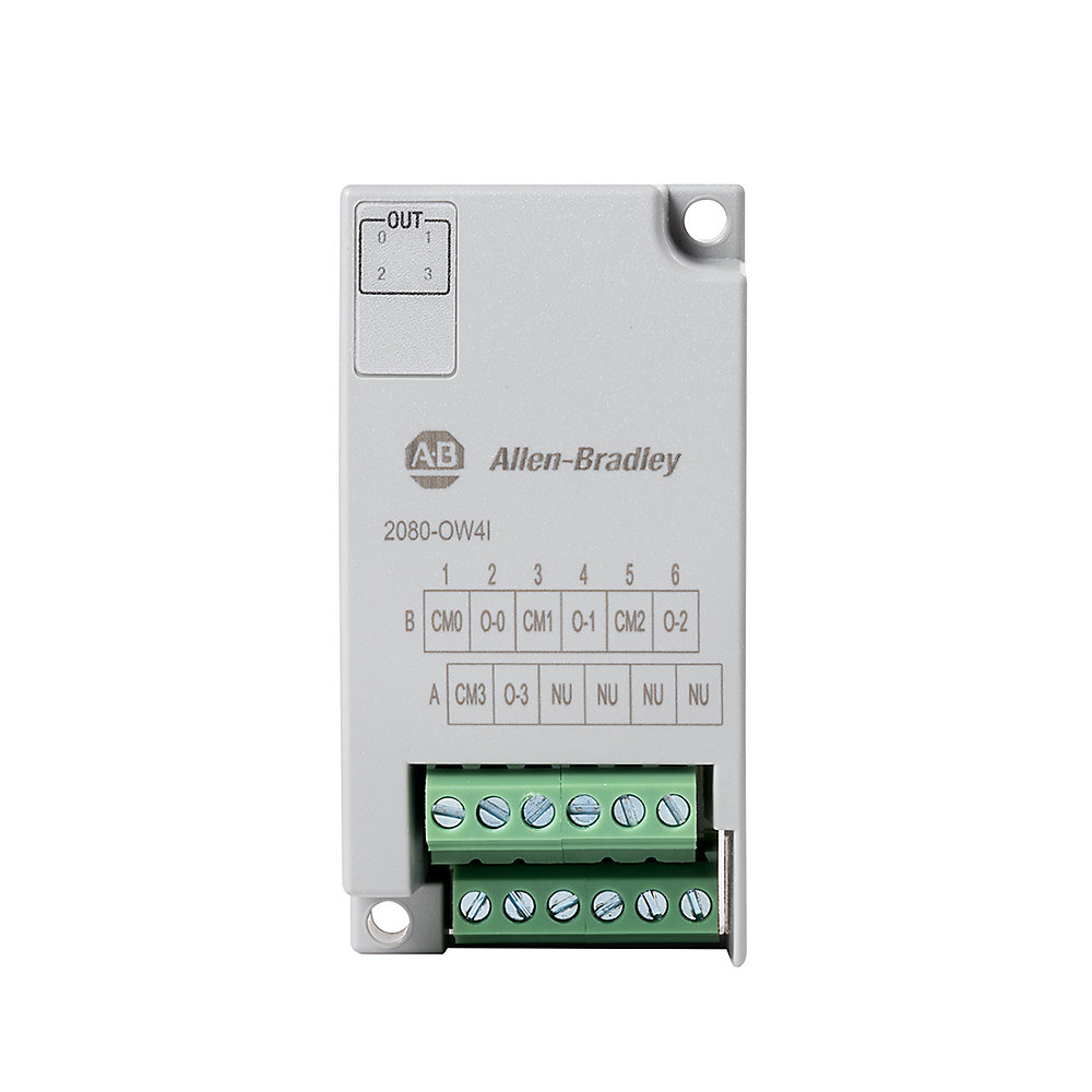
Loading
  • alt text
alt text
Best Selling
2080-OW4I

Micro800 4 Point Relay Output

PrintPrint
Print
EmailEmail
Share
Product RegistrationProduct Registration
QR code
Allen-Bradley 2080-OW4I product image
Lifecycle status: Active
Add to BoM
  • Get Support
Technical Specifications
General
Electrical
Environmental
Construction
Mechanical
Certification
Drawings
Documents
Certifications
Alternative Products
Technotes
I/O Isolation
Isolated
I/O Status Indication
LED
Digital inputs configurable
False
Digital outputs configurable
False
Type of voltage (input voltage)
DC
Type of output voltage
DC
Type of digital output
Relay
Type of electric connection
Screw connection
Status indicator
4 yellow
Output delay time, max
OFF to ON: 10 ms, ON to OFF: 10 ms
Wiring category
2 - on signal ports, 2 - on power ports
Number of I/O
4-channel relay output
Relay contact, continuous
2.0A @ 120V AC maximum volts, 0.35 power factor
Relay contact, make
7.5A @ 240V AC maximum volts, 0.35 power factor
Relay contact, break
28VA @ 24V DC maximum volts, 0.35 power factor
Pilot duty rating
C300, R150
Insulation stripping length
5 mm
Wire size
0.05...1.31 mm2 (30...16 AWG) solid copper wire rated @ 90 °C (194 °F ) insulation maximum
Isolation voltage
240V (continuous), reinforce insulation type, between output channels and output channels to backplane type tested for 60 s @ 1480V AC Outputs to Outputs, Outputs to Backplane
Redundancy
False
SIL according to IEC 61508
None
Minimum load per point
10 mA
Initial contact resistance of relay, max
30 mohm
Wire type
Copper
Backplane power
3.3V DC @ 38mA
Inrush current
<120mA @ 3.3V, <120mA @ 24V
Output current, resistive
2A @ 5...30V DC, 0.5A @ 48V DC, 0.22A @ 125V DC, 2A @ 125V AC, 2A @ 240V AC
Output power, resistive, max
250VA for 125V AC resistive loads, 480VA for 240V AC resistive loads, 60VA for 30V DC resistive loads, 24VA for 48V DC resistive loads, 27.5VA for 125V DC resistive loads
Output current, inductive
1.0 A steady state @ 5...28V DC @ 0.93A steady state @ 30V DC @ 0.5A steady state @ 48V DC @ 0.22A steady state @ 125V DC @ 2.0A steady state, 15 A make @ 125V AC, PF - cos θ = 0.4, 2.0 A steady state, 7.5 A make @ 240V AC, PF - cos θ = 0.4
Surrounding air temperature, max
65 °C
North American temperature code
T4
Relative humidity
5...95% noncondensing
Operating temperature
-20 to 65 °C
Nonoperating temperature
40 to 85 °C
Enclosure type rating
None (open-style)
Terminal base screw torque, max
0.19 Nm (1.7 in-lb.), using a 2.5 mm
Shock
Operating: 10 g
Vibration
2.0 G @ 10…500 Hz
Mounting torque
0.2 nm
Explosion safety category for gas
None
Explosion safety category for dust
None
Drawings
3D STP (STEP) Model Download (ZIP)
Product Drawing Drawing (DXF)
Drawings
3D STP (STEP) Model Download (ZIP)
Product Drawing Drawing (DXF)
Sign in to your Rockwell Automation account to view and download technical drawings.
Sign In
Type Resource Publication
General Product Cutsheet --
General Installation Guide --
User Manual 2080-um004_-en-e 2080-UM004
User Manual Micro800 Plug-in Modules User Manual 2080-UM002
Looking for more documentation?
Find curated technical documentation for this product in the Technical Documentation Center, or search our full Literature Library.
Visit the Technical Documentation Center Search the Literature Library
UKCA DOC
  • UKCA DOC

This product was certified with the above certifications as of 2025-09-10. Products sold before or after this date might carry different certifications. Please review the product label to check for the certifications your specific product carries.

Items Per Page:
1-1 of 1
Looking for more Technotes?
Find questions and answers from Rockwell Automation technical experts for this product in our Knowledgebase.
Search Knowledgebase
Technical Specifications
I/O Isolation
Isolated
I/O Status Indication
LED
Digital inputs configurable
False
Digital outputs configurable
False
Type of voltage (input voltage)
DC
Type of output voltage
DC
Type of digital output
Relay
Type of electric connection
Screw connection
Status indicator
4 yellow
Output delay time, max
OFF to ON: 10 ms, ON to OFF: 10 ms
Wiring category
2 - on signal ports, 2 - on power ports
Number of I/O
4-channel relay output
Relay contact, continuous
2.0A @ 120V AC maximum volts, 0.35 power factor
Relay contact, make
7.5A @ 240V AC maximum volts, 0.35 power factor
Relay contact, break
28VA @ 24V DC maximum volts, 0.35 power factor
Pilot duty rating
C300, R150
Insulation stripping length
5 mm
Wire size
0.05...1.31 mm2 (30...16 AWG) solid copper wire rated @ 90 °C (194 °F ) insulation maximum
Isolation voltage
240V (continuous), reinforce insulation type, between output channels and output channels to backplane type tested for 60 s @ 1480V AC Outputs to Outputs, Outputs to Backplane
Redundancy
False
SIL according to IEC 61508
None
Minimum load per point
10 mA
Initial contact resistance of relay, max
30 mohm
Wire type
Copper
Backplane power
3.3V DC @ 38mA
Inrush current
<120mA @ 3.3V, <120mA @ 24V
Output current, resistive
2A @ 5...30V DC, 0.5A @ 48V DC, 0.22A @ 125V DC, 2A @ 125V AC, 2A @ 240V AC
Output power, resistive, max
250VA for 125V AC resistive loads, 480VA for 240V AC resistive loads, 60VA for 30V DC resistive loads, 24VA for 48V DC resistive loads, 27.5VA for 125V DC resistive loads
Output current, inductive
1.0 A steady state @ 5...28V DC @ 0.93A steady state @ 30V DC @ 0.5A steady state @ 48V DC @ 0.22A steady state @ 125V DC @ 2.0A steady state, 15 A make @ 125V AC, PF - cos θ = 0.4, 2.0 A steady state, 7.5 A make @ 240V AC, PF - cos θ = 0.4
Surrounding air temperature, max
65 °C
North American temperature code
T4
Relative humidity
5...95% noncondensing
Operating temperature
-20 to 65 °C
Nonoperating temperature
40 to 85 °C
Enclosure type rating
None (open-style)
Terminal base screw torque, max
0.19 Nm (1.7 in-lb.), using a 2.5 mm
Shock
Operating: 10 g
Vibration
2.0 G @ 10…500 Hz
Mounting torque
0.2 nm
Explosion safety category for gas
None
Explosion safety category for dust
None
Drawings
Drawings
3D STP (STEP) Model Download (ZIP)
Product Drawing Drawing (DXF)
Drawings
3D STP (STEP) Model Download (ZIP)
Product Drawing Drawing (DXF)
Sign in to your Rockwell Automation account to view and download technical drawings.
Sign In
Documents
Product Cutsheet General
--
Installation Guide General
--
2080-um004_-en-e User Manual
2080-UM004
Micro800 Plug-in Modules User Manual User Manual
2080-UM002
Type Resource Publication
General Product Cutsheet --
General Installation Guide --
User Manual 2080-um004_-en-e 2080-UM004
User Manual Micro800 Plug-in Modules User Manual 2080-UM002
Looking for more documentation?
Find curated technical documentation for this product in the Technical Documentation Center, or search our full Literature Library.
Visit the Technical Documentation Center Search the Literature Library
Certifications
UKCA DOC
  • UKCA DOC

This product was certified with the above certifications as of 2025-09-10. Products sold before or after this date might carry different certifications. Please review the product label to check for the certifications your specific product carries.

Alternative Products
Items Per Page:
1-1 of 1
Technotes
Looking for more Technotes?
Find questions and answers from Rockwell Automation technical experts for this product in our Knowledgebase.
Search Knowledgebase
Loading
Find your nearest distributor
Contact your distributor in {0}
Change location
EmailEmail
PhonePhone
Find a partner
Micro800 4 Point Relay Output
CloseClose
2080-OW4I
Close
Print
Allen-Bradley 2080-OW4I product image
Phone:
Call
Rockwell Automation Home
Copyright ©2025 Rockwell Automation, Inc.
Sign in to your Rockwell Automation account to submit a repair documentation request.
Sign In
Request repair documentation
All fields with * are required for processing your request.
This field is required
Documentation of liability insurance is required for anyone who is requesting documentation for product repairs.
UploadUpload
Please upload documentation of liability insurance.*
1 file selected
CloseClose
File size is too large. Must be less than 5 MB.
Accepted file types: zip, pdf; Maximum size: 5 MB.
Right to Repair Terms and Conditions
Rockwell Automation is making, parts, and service documentation available at your request in compliance with applicable right to repair laws and regulations. By signing below, you are agreeing to the following terms and conditions of your purchase of Rockwell Automation genuine repair parts for repair of a Rockwell Automation product. As used below, “Self Service Repair Parts” means genuine Rockwell Automation parts (components of Rockwell Automation products) purchased from Rockwell Automation for installation in a Rockwell Automation product as part of a Self Service Repair. Self Service Repair Parts may be new or previously used genuine Rockwell Automation parts that have been tested and passed Rockwell Automation functional requirements. “Self Service Repair Tools” means equipment and related materials purchased for the purpose of performing repairs.
Your request has been successfully submitted.
Please allow up to 5 business days to receive a response to your inquiry.
  1. Chevron LeftChevron Left Rockwell Automation Home
  2. Chevron LeftChevron Left Products
Please update your cookie preferences to continue.
This feature requires cookies to enhance your experience. Please update your preferences to allow for these cookies:
  • Social Media Cookies
  • Functional Cookies
  • Performance Cookies
  • Marketing Cookies
  • All Cookies
You can update your preferences at any time. For more information please see our {0} Privacy Policy
CloseClose