Loading
View all 194E Load Switches
Print
Share
QR code
JSON
  • alt text
alt text
Chevron LeftChevron Left
alt text
Chevron LeftChevron Left
Allen-Bradley logo
Preferred
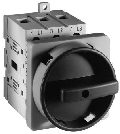
194E-E80-1753

80 A 194E Load switch

Serial #:
This product has not been verified. Please {} to confirm authenticity. register your product
Lifecycle status: Active
Description
IEC Load Switch, Open - Front / Door, OFF-ON 90°, 80A, 3 Poles
  • Add to BOM
  • Repair services
  • Get support
Preferred
194E-E80-1753

80 A 194E Load switch

Serial #:
This product has not been verified. Please {} to confirm authenticity. register your product
  • alt text
alt text
Chevron LeftChevron Left
alt text
Chevron LeftChevron Left
Allen-Bradley logo
Lifecycle status: Active
Description
IEC Load Switch, Open - Front / Door, OFF-ON 90°, 80A, 3 Poles
  • Add to BOM
  • Repair services
  • Get support
Find your nearest distributor
Contact your distributor in {0}
Change location
PhonePhone
Find a partner
Find your nearest distributor
Contact your distributor in {0}
Change location
PhonePhone
Find a partner
Overview
Physical Characteristics
Mechanical
Construction
Compliance & Environment
Standards & Protection
Electrical & Connectivity
Power & Electrical Characteristics
Drawings
Documents
Certifications
Accessories
Alternative Products
Technotes
Unique Product Identifier
194E-E80-1753
UPC
662072554258
Estimated Lead Time
5 days
Standard Warranty Duration

1 year See details

Country of Origin
Poland
Mechanical
Actuator type
Select actuator separately
Degree of protection (IP), front side
IP20
Degree of protection (NEMA)
Other
Fine strands wire gauge
4...35 mm2 (10...1 AWG)
Knockouts
PG-type cable gland entry
Mechanical life operations
200000
Protection class according to IEC 529
Switch bodies: IP20 @ motor rating 60 Hz
Rigid wire gauge
4...50 mm2 (10...1 AWG)
Switch configuration
OFF-ON 90°
Tightening torque
5.6 Nm (50 in-lb)
Version as emergency stop installation
False
Version as main switch
True
Version as maintenance-/service switch
True
Version as reversing switch
False
Wire gauge, max
Terminal size per IEC 947-1: A9
Construction
Device construction
Built-in device fixed built-in technique
Installation
Open-front/door
Suitable for distribution board installation
False
Suitable for front mounting 4-hole
True
Suitable for front mounting centre
True
Switch body depth, approx
90 mm (3-35/64 in) @ 80 A
Switch body height, approx
90 mm (3-35/64 in) @ 80 A
Switch body width, approx
72 mm (2-27/32 in) @ 80 A
Ambient enclosed temperature
-20 °C
Ambient operation temperature
-25 °C
Ambient storage temperature
-40 °C
Conditioned rated short-circuit current Iq
30 kA
Continuous current
UL/CSA (applications): 80 A
Conventional enclosed thermal current (Ie)
80 A per IEC
Conventional free air thermal current (Ith)
100 A per IEC
Fuse rating of circuit (type g, G), max
Short circuit current (co-ordination type 2): 80A @ 400/415V
Hp motor rating
UL/CSA application: 50Hp @ 600V, 60 Hz, 3 pole, 3 phase
Lost power per pole
3.6 W
Max. rated operation voltage Ue AC
690 V
Motor FLA rating
UL/CSA application: 68A @ 240V, 60 Hz, 3 pole, 3 phase
Motor drive integrated
False
Number of auxiliary contacts as normally closed contact
0
Number of auxiliary contacts as normally open contact
0
Number of switches
1
Rated breaking capacity
AC-23A (cosφ 0.45): 800A @ 400V
Rated current (Ie)
DC-21A (for resistive loads): 80A @ 96V, 2 pole in series, T ≤1 ms, Ue max = 660V
Rated frequency
60 Hz
Rated impulse voltage (Uimp)
8 kV per UL, CSA
Rated isolation voltage (Ui)
690V per IEC
Rated operation power at AC-23, 400 V
37 kw
Rated operation power at AC-3, 400 V
30 kw
Rated operational voltage (Ue)
690V per IEC
Rated permanent current Iu
80 A
Rated power (Pe)
AC-3: 30 kW @ 690V
Rated short-time withstand current lcw
2500 kA
Switch size
80 A
Switching rate
120 ops/h
Test voltage (Ui)
2.5kV @ 1min
Type of electrical connection of main circuit
Screw connection
Voltage release optional
False
Drawings
Mount STEP Model (STP) Download (STP)
Product Drawing Drawing (DXF)
Drawings
Mount STEP Model (STP) Download (STP)
Product Drawing Drawing (DXF)
Sign in to your Rockwell Automation account to view and download technical drawings.
Sign In
General Publication
Product Cutsheet --
Installation Instructions Publication
194e-in010_-en-p 194E-IN010
Technical Data Publication
194-td002_-en-p 194-TD002
Looking for more documentation?
Find curated technical documentation for this product in the Technical Documentation Center, or search our full Literature Library.
Visit the Technical Documentation Center Search the Literature Library
China CCC IECEE Scheme
  • China CCC
  • IECEE Scheme

This product was certified with the above certifications as of 2026-07-16. Products sold before or after this date might carry different certifications. Please review the product label to check for the certifications your specific product carries.

Looking for certification documents?
Explore certifications for this product and more in our comprehensive Literature Library.

Search the Literature Library
Regulatory Information
EU Importer Address

Rockwell Automation N.V
Pegasus Park
De Kleetlaan 12A
1831 Diegem
Belgium

EU Authorized Representative Address

Rockwell Automation N.V
Pegasus Park
De Kleetlaan 12A
1831 Diegem
Belgium

Items Per Page:
1-1 of 1
Items Per Page:
1-1 of 1
Technotes
Looking for more Technotes?
Find questions and answers from Rockwell Automation technical experts for this product in our Knowledgebase.
Search Knowledgebase
Overview
Unique Product Identifier
194E-E80-1753
UPC
662072554258
Estimated Lead Time
5 days
Standard Warranty Duration

1 year See details

Country of Origin
Poland
Physical Characteristics
Mechanical
Actuator type
Select actuator separately
Degree of protection (IP), front side
IP20
Degree of protection (NEMA)
Other
Fine strands wire gauge
4...35 mm2 (10...1 AWG)
Knockouts
PG-type cable gland entry
Mechanical life operations
200000
Protection class according to IEC 529
Switch bodies: IP20 @ motor rating 60 Hz
Rigid wire gauge
4...50 mm2 (10...1 AWG)
Switch configuration
OFF-ON 90°
Tightening torque
5.6 Nm (50 in-lb)
Version as emergency stop installation
False
Version as main switch
True
Version as maintenance-/service switch
True
Version as reversing switch
False
Wire gauge, max
Terminal size per IEC 947-1: A9
Construction
Device construction
Built-in device fixed built-in technique
Installation
Open-front/door
Suitable for distribution board installation
False
Suitable for front mounting 4-hole
True
Suitable for front mounting centre
True
Switch body depth, approx
90 mm (3-35/64 in) @ 80 A
Switch body height, approx
90 mm (3-35/64 in) @ 80 A
Switch body width, approx
72 mm (2-27/32 in) @ 80 A
Compliance & Environment
Ambient enclosed temperature
-20 °C
Ambient operation temperature
-25 °C
Ambient storage temperature
-40 °C
Electrical & Connectivity
Conditioned rated short-circuit current Iq
30 kA
Continuous current
UL/CSA (applications): 80 A
Conventional enclosed thermal current (Ie)
80 A per IEC
Conventional free air thermal current (Ith)
100 A per IEC
Fuse rating of circuit (type g, G), max
Short circuit current (co-ordination type 2): 80A @ 400/415V
Hp motor rating
UL/CSA application: 50Hp @ 600V, 60 Hz, 3 pole, 3 phase
Lost power per pole
3.6 W
Max. rated operation voltage Ue AC
690 V
Motor FLA rating
UL/CSA application: 68A @ 240V, 60 Hz, 3 pole, 3 phase
Motor drive integrated
False
Number of auxiliary contacts as normally closed contact
0
Number of auxiliary contacts as normally open contact
0
Number of switches
1
Rated breaking capacity
AC-23A (cosφ 0.45): 800A @ 400V
Rated current (Ie)
DC-21A (for resistive loads): 80A @ 96V, 2 pole in series, T ≤1 ms, Ue max = 660V
Rated frequency
60 Hz
Rated impulse voltage (Uimp)
8 kV per UL, CSA
Rated isolation voltage (Ui)
690V per IEC
Rated operation power at AC-23, 400 V
37 kw
Rated operation power at AC-3, 400 V
30 kw
Rated operational voltage (Ue)
690V per IEC
Rated permanent current Iu
80 A
Rated power (Pe)
AC-3: 30 kW @ 690V
Rated short-time withstand current lcw
2500 kA
Switch size
80 A
Switching rate
120 ops/h
Test voltage (Ui)
2.5kV @ 1min
Type of electrical connection of main circuit
Screw connection
Voltage release optional
False
Drawings
Drawings
Mount STEP Model (STP) Download (STP)
Product Drawing Drawing (DXF)
Drawings
Mount STEP Model (STP) Download (STP)
Product Drawing Drawing (DXF)
Sign in to your Rockwell Automation account to view and download technical drawings.
Sign In
Documents
Product Cutsheet General
--
194e-in010_-en-p Installation Instructions
194E-IN010
194-td002_-en-p Technical Data
194-TD002
General Publication
Product Cutsheet --
Installation Instructions Publication
194e-in010_-en-p 194E-IN010
Technical Data Publication
194-td002_-en-p 194-TD002
Looking for more documentation?
Find curated technical documentation for this product in the Technical Documentation Center, or search our full Literature Library.
Visit the Technical Documentation Center Search the Literature Library
Certifications
{name=China CCC, link=http://literature.rockwellautomation.com/idc/groups/literature/documents/ct/194e-ct001_-en-e.pdf} {name=IECEE Scheme, link=http://literature.rockwellautomation.com/idc/groups/literature/documents/ct/194e-ct007_-en-e.pdf}
  • China CCC
  • IECEE Scheme

This product was certified with the above certifications as of 2026-07-16. Products sold before or after this date might carry different certifications. Please review the product label to check for the certifications your specific product carries.

Looking for certification documents?
Explore certifications for this product and more in our comprehensive Literature Library.

Search the Literature Library
Regulatory Information
EU Importer Address

Rockwell Automation N.V
Pegasus Park
De Kleetlaan 12A
1831 Diegem
Belgium

EU Authorized Representative Address

Rockwell Automation N.V
Pegasus Park
De Kleetlaan 12A
1831 Diegem
Belgium

Accessories
Items Per Page:
1-1 of 1
Alternative Products
Items Per Page:
1-1 of 1
Technotes
Technotes
Looking for more Technotes?
Find questions and answers from Rockwell Automation technical experts for this product in our Knowledgebase.
Search Knowledgebase
InformationInformation
Multiple countries of origin based on manufacturing location

80 A 194E Load switch
CloseClose
194E-E80-1753
Close
Print
Phone:
Call
InformationInformation

Please review your distributor selection

Choose distributor
Rockwell Automation Home
Copyright ©2026 Rockwell Automation, Inc.
Environmental compliance inquiry
All fields with * are required.
This field is required
Your inquiry has been successfully submitted.
Please allow up to 5 business days to receive a response to your inquiry.
You can now close this window.
There was an error submitting your inquiry.
Please try again.
Sign in to your Rockwell Automation account to submit a repair documentation request.
Sign In
Request repair documentation
All fields with * are required for processing your request.
Please enter your business email address
This field is required
Documentation of liability insurance is required for anyone who is requesting documentation for product repairs.
UploadUpload
Please upload documentation of liability insurance.*
1 file selected
CloseClose
File size is too large. Must be less than 5 MB.
Accepted file types: zip, pdf; Maximum size: 5 MB.
This field is required
Right to Repair Terms and Conditions
Rockwell Automation is making, parts, and service documentation available at your request in compliance with applicable right to repair laws and regulations. By signing below, you are agreeing to the following terms and conditions of your purchase of Rockwell Automation genuine repair parts for repair of a Rockwell Automation product. As used below, “Self Service Repair Parts” means genuine Rockwell Automation parts (components of Rockwell Automation products) purchased from Rockwell Automation for installation in a Rockwell Automation product as part of a Self Service Repair. Self Service Repair Parts may be new or previously used genuine Rockwell Automation parts that have been tested and passed Rockwell Automation functional requirements. “Self Service Repair Tools” means equipment and related materials purchased for the purpose of performing repairs.
This field is required
Your request has been successfully submitted.
Please allow up to 5 business days to receive a response to your inquiry.
This catalog number is not currently eligible, please check the number you have entered or learn more about our repair services offered.
  1. Chevron LeftChevron Left Rockwell Automation Home
  2. Chevron LeftChevron Left Products
Please update your cookie preferences to continue.
This feature requires cookies to enhance your experience. Please update your preferences to allow for these cookies:
  • Social Media Cookies
  • Functional Cookies
  • Performance Cookies
  • Marketing Cookies
  • All Cookies
You can update your preferences at any time. For more information please see our {0} Privacy Policy
CloseClose