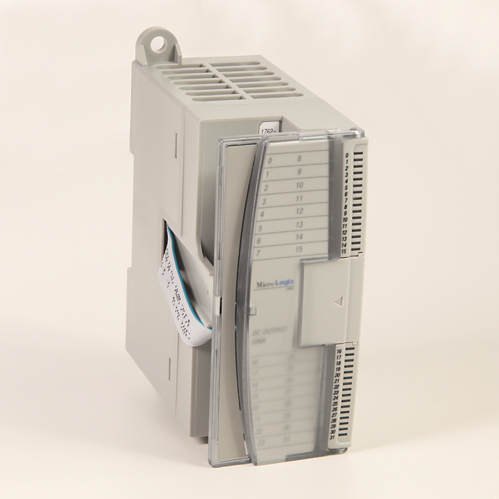
MicroLogix 4 Point Analog Comb Module
| Unique Product Identifier |
1762-IF2OF2
|
|---|---|
| UPC |
612598207190
|
| Estimated Lead Time |
5 days
|
| Standard Warranty Duration |
1 year See details |
| Country of Origin |
Malaysia
|
The information provided by Rockwell Automation on www.rockwellautomation.com (the “Site”) is for demonstration purposes only and may be incomplete or inaccurate. All information is provided “as is”, and Rockwell Automation makes no representations or warranties of any kind, express or implied, regarding the accuracy, adequacy, validity, reliability, or completeness of any information on the Site. Use of this information is at your own risk.
| Class |
Progmable Logic Controller
|
|---|---|
| Current Range |
4-20
|
| Depth |
87
|
| Height |
90
|
| I/O Isolation |
Isolated
|
| I/O Ports |
4 Channel Analog Combo Module
|
| I/O Status Indication |
LED
|
| Module Interfaces |
Analog combination
|
| Number Of Channels |
4 point
|
| Output |
2 Point, 0-10V, 4-20 mA
|
| Temperature Rating |
-20…65 °C (-4…149 °F)
|
| Resolution of the analogue inputs |
12 bit
|
|---|---|
| Input, current |
True
|
| Input, voltage |
True
|
| Input, resistor |
False
|
| Input, resistance thermometer |
False
|
| Input, thermocouple |
False
|
| Input signal, configurable |
True
|
| Output, current |
True
|
| Output, voltage |
True
|
| Output signal configurable |
True
|
| Analogue inputs configurable |
True
|
| Analogue outputs configurable |
True
|
| Type of electric connection |
Screw connection
|
| Fast transient burst |
IEC1000-4-4: 2kV @ 5kHz
|
| Conducted immunity |
IEC 1000-4-6: 10V @ 0.15...80MHz
|
| Radiated immunity |
IEC1000-4-3: 10 V/m, 80...1,000 MHz, 80% Alitude modulation, +900 MHz keyed carrier
|
| Suitable for safety functions |
False
|
| Surge immunity |
IEC1000-4-5: 1kV galvanic gun
|
| Module power LED |
On: indicates power is applied
|
| Common mode voltage range |
-27 to 27V
|
|---|---|
| Load range on voltage output |
>1KΩ
|
| Output update time |
Typical: 4.5 ms
|
| A/D converter type |
Successive approximation
|
| Number of inputs |
2 differential (unipolar)
|
| Number of outputs |
2 single-ended (unipolar)
|
| D/A converter type |
Resistor string
|
| Non-linearity |
±0.12% (in % full scale)
|
| Common mode rejection |
>55 dB at 50 and 60 Hz
|
| Input update time |
Typical: 2.5 ms
|
| Typical overall accuracy |
±1.17% full scale @ -20...65 °C (Only applicable to Series B I/O modules.), ±0.5% full scale @ 25 °C
|
| Input impedance |
Voltage Terminal: 200 KΩ
|
| Reactive load, voltage output |
<1 µF
|
| Reactive load, current output |
<0.1 mH
|
| Current input protection |
-32 mA
|
| Voltage input protection |
-30 V
|
| Output protection |
-32 mA
|
| Open and short-circuit protection |
Continuous
|
| Resistive load on current output |
0...500 Ω (includes wire resistance)
|
| Output ripple range |
<±0.1% @ 0...500Hz (referred to output range)
|
| Channel diagnostics |
Over or under range or open circuit condition by bit reporting for analog inputs
|
| Analog normal operating range |
Voltage: 0...10V DC
|
|---|---|
| Bus current draw, max |
40mA @ 5V DC, 105mA @ 24V DC
|
| Full scale analog ranges |
Voltage: 0...10.5V DC
|
| Repeatability |
-0.12 to 0.12%
|
| Input and output group to system isolation |
30V AC/30V DC rated working voltage (N.E.C. Class 2 required) (IEC Class 2 reinforced insulation) type test: 500V AC or 707V DC @ 1min
|
| RAW/Proportional data |
32,760 @ 0...10V DC, 32,760 @ 4...20 mA, 31,200 @ 4...20 mA, 6240 @ 4...20 mA
|
|---|---|
| Scaled-for-PID |
16,380 @ 0...10V DC, 16,380 @ 4...20 DC, 15,600 @ 4...20V DC, 3120 @ 4...20V DC
|
| Full Scale range |
10.5V DC @ 0...10V DC, 21.0mA @ 4...20mA, 20.0mA @ 4...20mA, 4.0mA @ 4...20mA
|
| Height |
90 mm
|
|---|---|
| Width |
40 mm
|
| Depth |
87 mm
|
| Recommended cable |
Belden 8761 (shielded), (For 1762-IT4, shielded thermocouple extension wire for the specific type of thermocouple you are using. Follow thermocouple manufacturer’s recommendations.)
|
| Weight |
Shipping: 240 g (0.53 lbs.) approximately (with cartoon)
|
|---|---|
| Vibration |
Operating: 5 g @ 10...500 Hz, 0.030 in. max. peak-to-peak
|
| Shock |
Operating: 30 g
|
| Operating temperature |
-20 °C
|
|---|---|
| ESD immunity |
EN 61000-4-2, 4 kV contact, 8 kV air, 4 kV indirect
|
| Hazardous environment class |
Hazardous Location, Class I, Division 2 Groups A, B, C, D (UL 1604, C-UL under CSA C22.2 No. 213)
|
| Operating altitude |
2000 m
|
| Storage temperature |
-40 °C
|
| Radiated and conducted emissions |
EN50081-2: Class A
|
| Operating humidity |
5...95% noncondensing
|
| Drawings | |
|---|---|
| Product Drawing | Drawing (DWG) |
| Drawings |
|---|
| Product Drawing Drawing (DWG) |
| General | Publication |
|---|---|
| Product Cutsheet | -- |
| Selection Guide | 1761-SG001 |
This product was certified with the above certifications as of 2026-05-19. Products sold before or after this date might carry different certifications. Please review the product label to check for the certifications your specific product carries.
Looking for certification documents?
Explore certifications for this product and more in our comprehensive Literature Library.
| EU Importer Address |
Rockwell Automation N.V |
|---|---|
| EU Authorized Representative Address |
Rockwell Automation N.V |
| Technotes |
|---|
Overview
| Unique Product Identifier |
1762-IF2OF2
|
|---|---|
| UPC |
612598207190
|
| Estimated Lead Time |
5 days
|
| Standard Warranty Duration |
1 year See details |
| Country of Origin |
Malaysia
|
The information provided by Rockwell Automation on www.rockwellautomation.com (the “Site”) is for demonstration purposes only and may be incomplete or inaccurate. All information is provided “as is”, and Rockwell Automation makes no representations or warranties of any kind, express or implied, regarding the accuracy, adequacy, validity, reliability, or completeness of any information on the Site. Use of this information is at your own risk.
Electrical & Connectivity
| Class |
Progmable Logic Controller
|
|---|---|
| Current Range |
4-20
|
| Depth |
87
|
| Height |
90
|
| I/O Isolation |
Isolated
|
| I/O Ports |
4 Channel Analog Combo Module
|
| I/O Status Indication |
LED
|
| Module Interfaces |
Analog combination
|
| Number Of Channels |
4 point
|
| Output |
2 Point, 0-10V, 4-20 mA
|
| Temperature Rating |
-20…65 °C (-4…149 °F)
|
| Resolution of the analogue inputs |
12 bit
|
|---|---|
| Input, current |
True
|
| Input, voltage |
True
|
| Input, resistor |
False
|
| Input, resistance thermometer |
False
|
| Input, thermocouple |
False
|
| Input signal, configurable |
True
|
| Output, current |
True
|
| Output, voltage |
True
|
| Output signal configurable |
True
|
| Analogue inputs configurable |
True
|
| Analogue outputs configurable |
True
|
| Type of electric connection |
Screw connection
|
| Fast transient burst |
IEC1000-4-4: 2kV @ 5kHz
|
| Conducted immunity |
IEC 1000-4-6: 10V @ 0.15...80MHz
|
| Radiated immunity |
IEC1000-4-3: 10 V/m, 80...1,000 MHz, 80% Alitude modulation, +900 MHz keyed carrier
|
| Suitable for safety functions |
False
|
| Surge immunity |
IEC1000-4-5: 1kV galvanic gun
|
| Module power LED |
On: indicates power is applied
|
| Common mode voltage range |
-27 to 27V
|
|---|---|
| Load range on voltage output |
>1KΩ
|
| Output update time |
Typical: 4.5 ms
|
| A/D converter type |
Successive approximation
|
| Number of inputs |
2 differential (unipolar)
|
| Number of outputs |
2 single-ended (unipolar)
|
| D/A converter type |
Resistor string
|
| Non-linearity |
±0.12% (in % full scale)
|
| Common mode rejection |
>55 dB at 50 and 60 Hz
|
| Input update time |
Typical: 2.5 ms
|
| Typical overall accuracy |
±1.17% full scale @ -20...65 °C (Only applicable to Series B I/O modules.), ±0.5% full scale @ 25 °C
|
| Input impedance |
Voltage Terminal: 200 KΩ
|
| Reactive load, voltage output |
<1 µF
|
| Reactive load, current output |
<0.1 mH
|
| Current input protection |
-32 mA
|
| Voltage input protection |
-30 V
|
| Output protection |
-32 mA
|
| Open and short-circuit protection |
Continuous
|
| Resistive load on current output |
0...500 Ω (includes wire resistance)
|
| Output ripple range |
<±0.1% @ 0...500Hz (referred to output range)
|
| Channel diagnostics |
Over or under range or open circuit condition by bit reporting for analog inputs
|
Technical Specifications
| Analog normal operating range |
Voltage: 0...10V DC
|
|---|---|
| Bus current draw, max |
40mA @ 5V DC, 105mA @ 24V DC
|
| Full scale analog ranges |
Voltage: 0...10.5V DC
|
| Repeatability |
-0.12 to 0.12%
|
| Input and output group to system isolation |
30V AC/30V DC rated working voltage (N.E.C. Class 2 required) (IEC Class 2 reinforced insulation) type test: 500V AC or 707V DC @ 1min
|
| RAW/Proportional data |
32,760 @ 0...10V DC, 32,760 @ 4...20 mA, 31,200 @ 4...20 mA, 6240 @ 4...20 mA
|
|---|---|
| Scaled-for-PID |
16,380 @ 0...10V DC, 16,380 @ 4...20 DC, 15,600 @ 4...20V DC, 3120 @ 4...20V DC
|
| Full Scale range |
10.5V DC @ 0...10V DC, 21.0mA @ 4...20mA, 20.0mA @ 4...20mA, 4.0mA @ 4...20mA
|
Physical Characteristics
| Height |
90 mm
|
|---|---|
| Width |
40 mm
|
| Depth |
87 mm
|
| Recommended cable |
Belden 8761 (shielded), (For 1762-IT4, shielded thermocouple extension wire for the specific type of thermocouple you are using. Follow thermocouple manufacturer’s recommendations.)
|
| Weight |
Shipping: 240 g (0.53 lbs.) approximately (with cartoon)
|
|---|---|
| Vibration |
Operating: 5 g @ 10...500 Hz, 0.030 in. max. peak-to-peak
|
| Shock |
Operating: 30 g
|
Compliance & Environment
| Operating temperature |
-20 °C
|
|---|---|
| ESD immunity |
EN 61000-4-2, 4 kV contact, 8 kV air, 4 kV indirect
|
| Hazardous environment class |
Hazardous Location, Class I, Division 2 Groups A, B, C, D (UL 1604, C-UL under CSA C22.2 No. 213)
|
| Operating altitude |
2000 m
|
| Storage temperature |
-40 °C
|
| Radiated and conducted emissions |
EN50081-2: Class A
|
| Operating humidity |
5...95% noncondensing
|
Drawings
| Drawings | |
|---|---|
| Product Drawing | Drawing (DWG) |
| Drawings |
|---|
| Product Drawing Drawing (DWG) |
Documents
|
Product Cutsheet
General
-- |
|
Selection Guide
General
1761-SG001 |
| General | Publication |
|---|---|
| Product Cutsheet | -- |
| Selection Guide | 1761-SG001 |
Certifications
This product was certified with the above certifications as of 2026-05-19. Products sold before or after this date might carry different certifications. Please review the product label to check for the certifications your specific product carries.
Looking for certification documents?
Explore certifications for this product and more in our comprehensive Literature Library.
| EU Importer Address |
Rockwell Automation N.V |
|---|---|
| EU Authorized Representative Address |
Rockwell Automation N.V |
Technotes
| Technotes |
|---|