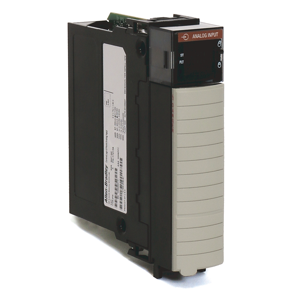
ControlLogix 8 Point Analog Input
| Unique Product Identifier |
1756-IF8I
|
|---|---|
| UPC |
885630245409
|
| Estimated Lead Time |
5 days
|
| Standard Warranty Duration |
1 year See details |
| Country of Origin |
Multiple
|
The information provided by Rockwell Automation on www.rockwellautomation.com (the “Site”) is for demonstration purposes only and may be incomplete or inaccurate. All information is provided “as is”, and Rockwell Automation makes no representations or warranties of any kind, express or implied, regarding the accuracy, adequacy, validity, reliability, or completeness of any information on the Site. Use of this information is at your own risk.
| Display |
Module Health, In Calibration,Mode, Input, Fault and,Communication Status
|
|---|---|
| Input Signal |
-10GǪ10V, 0GǪ10V, 0GǪ5V, 0G
|
| Isolation |
250V (continuous), reinforced,insulation type, inputs to,backplane. 250V (continuous),basic insulation type, input,to input
|
| Special Features |
Per Point Isolation
|
| Input, current |
True
|
|---|---|
| Input, voltage |
True
|
| Input, resistor |
False
|
| Input, resistance thermometer |
False
|
| Input, thermocouple |
False
|
| Input signal, configurable |
True
|
| Output, current |
False
|
| Output, voltage |
False
|
| Output signal configurable |
False
|
| Analogue inputs configurable |
True
|
| Analogue outputs configurable |
False
|
| Type of electric connection |
Screw-/spring clA connection
|
| Channel bandwidth |
Notch Filter configuration dependent
|
| Module keying |
Electronic, software configurable
|
| Module error over full temperature range |
0.1 %
|
| Module conversion method |
Sigma-Delta
|
| Input range |
-10...10V, 0…10V @ 0...5V, 0...20 mA
|
| Data format |
IEEE 32-bit floating point
|
| Wire category |
2 - on signal ports
|
| Overvoltage protection |
±30V DC maximum
|
| Common mode noise rejection |
120 dB @ 50/60 Hz
|
| Normal mode noise rejection |
80 dB @ 60 Hz
|
| Module input scan time, min |
1 ms
|
| Voltage and current ratings |
Backplane: 5.1V DC 200mA @ 24V DC 400 mA, Input voltage: -10V to +10V @ 0V to 10V @ 0V to 5V, Input current: 0 mA to 20 mA, Output current: 0 mA to 20 mA
|
| Settling time |
Notch Filter configuration dependent
|
| Total backplane power |
Voltage/Non-sourcing current mode: 4.6 W, Sourcing current mode: 10.6 W
|
| Thermal dissipation |
Voltage mode: 15.7 BTU/hr, Non-sourcing current mode: 17.4 BTU/hr, Sourcing current mode: 24.9 BTU/hr
|
| Current draw |
200mA @ 5.1V, Voltage/Non-sourcing current mode: 150mA @ 24V, Sourcing current mode: 400mA @ 24V (In sourcing current mode, the channel provides loop power.)
|
| Inputs |
Eight isolated channels - any combination of voltage or current mode
|
| Isolation voltage |
250V (continuous), reinforced insulation type, inputs to backplane, 250V (continuous), basic insulation type, input to input
|
| Power dissipation |
Voltage mode: 4.6 W (15.7 BTU/hr), Non-sourcing current mode: 5.1 W (17.4 BTU/hr), Sourcing current mode: 7.3 W (24.9 BTU/hr)
|
| Resolution |
24 bit, ±10.5V (1.49 µV/count), 0...10.5V (1.49 µV/count), 0...5.25V (1.49 µV/count), 0...21 mA (2.99 nA/count)
|
| Wire size |
0.33...2.1 mm² (22...14 AWG) solid or stranded shielded copper wire rated at 90 °C (194 °F), or greater, 1.2 mm (3/64 in.) insulation maximum
|
| Calibrated accuracy |
0.05% @ 25°C (77 °F)
|
| Open circuit detection time |
5 s
|
| Suitable for safety functions |
False
|
| Onboard data alarming |
True
|
| Scaling to engineering units |
True
|
| Real-time channel sampling |
True
|
| Sourcing voltage, min |
20V DC
|
| Sourcing voltage, max |
36V DC (open circuit)
|
| Sourcing current, max |
Current limited <45 mA (IN_x/I/SRC to RTN_x)
|
| Input impedance |
Voltage mode: 1 GΩ approximately (powered), Voltage mode: 7500 Ω approximately (unpowered), Current mode: 125 Ω approximately
|
|---|
| Surrounding air temperature, max |
60 °C
|
|---|---|
| North American temperature code |
T4
|
| Emissions |
IEC 61000-6-4
|
| ESD immunity |
6 kV contact discharges, 8 kV air discharges
|
| EFT/B immunity |
±4kV @ 5kHz on shielded signal ports
|
| Relative humidity |
5...95% noncondensing
|
| Conducted RF immunity |
10V rms with 1 kHz sine wave 80% AM from 150 kHz...80 MHz on shielded signal ports
|
| Surge transient immunity |
±2 kV line-earth (CM) on shielded signal ports
|
| Operating temperature |
0 to 60 °C
|
| Radiated RF immunity |
10 V/m with 1 kHz sine-wave 80% AM from 80...2000 MHz, 10 V/m with 200 Hz 50% pulse 100% AM @ 900 MHz, 10 V/m with 200 Hz 50% pulse 100% AM @ 1890 MHz, 3 V/m with 1 kHz sine-wave 80% AM from 2000...2700 MHz
|
| Nonoperating temperature |
-40 °C
|
| RTB keying |
User-defined mechanical
|
|---|---|
| Vibration |
2 G @ 10...500 Hz
|
| Shock |
Operating: 30 G, Non operating: 50 G
|
| Slot width |
1
|
| Enclosure type rating |
None (open-style)
|
|---|
| Environmental Compliance | |
|---|---|
| SVHC Information | |
| Environmental Compliance | |
| SVHC Information | |
| Environmental Compliance | |
| SVHC Information |
| Drawings | |
|---|---|
| 3-Dimensional STEP model (STP) | Download (ZIP) |
| Product Drawing | Drawing (DXF) |
| Drawings |
|---|
| 3-Dimensional STEP model (STP) Download (ZIP) |
| Product Drawing Drawing (DXF) |
| General | Publication |
|---|---|
| Product Cutsheet | -- |
| Technical Detail | -- |
| Product Profile | -- |
| Technical Data | Publication |
|---|---|
| 1756-td002_-en-e | 1756-TD002 |
- China CCC
- Safety
- Australian RCM
- Korean KC
- ATEX
- IECEx Scheme
- American Bureau of Shippin
- MOROCCO DOC
- Eurasion Economic Community
This product was certified with the above certifications as of 2026-05-19. Products sold before or after this date might carry different certifications. Please review the product label to check for the certifications your specific product carries.
Looking for certification documents?
Explore certifications for this product and more in our comprehensive Literature Library.
| EU Importer Address |
Rockwell Automation N.V |
|---|---|
| EU Authorized Representative Address |
Rockwell Automation N.V |
| Technotes |
|---|
Overview
| Unique Product Identifier |
1756-IF8I
|
|---|---|
| UPC |
885630245409
|
| Estimated Lead Time |
5 days
|
| Standard Warranty Duration |
1 year See details |
| Country of Origin |
Multiple
|
The information provided by Rockwell Automation on www.rockwellautomation.com (the “Site”) is for demonstration purposes only and may be incomplete or inaccurate. All information is provided “as is”, and Rockwell Automation makes no representations or warranties of any kind, express or implied, regarding the accuracy, adequacy, validity, reliability, or completeness of any information on the Site. Use of this information is at your own risk.
Electrical & Connectivity
| Display |
Module Health, In Calibration,Mode, Input, Fault and,Communication Status
|
|---|---|
| Input Signal |
-10GǪ10V, 0GǪ10V, 0GǪ5V, 0G
|
| Isolation |
250V (continuous), reinforced,insulation type, inputs to,backplane. 250V (continuous),basic insulation type, input,to input
|
| Special Features |
Per Point Isolation
|
| Input, current |
True
|
|---|---|
| Input, voltage |
True
|
| Input, resistor |
False
|
| Input, resistance thermometer |
False
|
| Input, thermocouple |
False
|
| Input signal, configurable |
True
|
| Output, current |
False
|
| Output, voltage |
False
|
| Output signal configurable |
False
|
| Analogue inputs configurable |
True
|
| Analogue outputs configurable |
False
|
| Type of electric connection |
Screw-/spring clA connection
|
| Channel bandwidth |
Notch Filter configuration dependent
|
| Module keying |
Electronic, software configurable
|
| Module error over full temperature range |
0.1 %
|
| Module conversion method |
Sigma-Delta
|
| Input range |
-10...10V, 0…10V @ 0...5V, 0...20 mA
|
| Data format |
IEEE 32-bit floating point
|
| Wire category |
2 - on signal ports
|
| Overvoltage protection |
±30V DC maximum
|
| Common mode noise rejection |
120 dB @ 50/60 Hz
|
| Normal mode noise rejection |
80 dB @ 60 Hz
|
| Module input scan time, min |
1 ms
|
| Voltage and current ratings |
Backplane: 5.1V DC 200mA @ 24V DC 400 mA, Input voltage: -10V to +10V @ 0V to 10V @ 0V to 5V, Input current: 0 mA to 20 mA, Output current: 0 mA to 20 mA
|
| Settling time |
Notch Filter configuration dependent
|
| Total backplane power |
Voltage/Non-sourcing current mode: 4.6 W, Sourcing current mode: 10.6 W
|
| Thermal dissipation |
Voltage mode: 15.7 BTU/hr, Non-sourcing current mode: 17.4 BTU/hr, Sourcing current mode: 24.9 BTU/hr
|
| Current draw |
200mA @ 5.1V, Voltage/Non-sourcing current mode: 150mA @ 24V, Sourcing current mode: 400mA @ 24V (In sourcing current mode, the channel provides loop power.)
|
| Inputs |
Eight isolated channels - any combination of voltage or current mode
|
| Isolation voltage |
250V (continuous), reinforced insulation type, inputs to backplane, 250V (continuous), basic insulation type, input to input
|
| Power dissipation |
Voltage mode: 4.6 W (15.7 BTU/hr), Non-sourcing current mode: 5.1 W (17.4 BTU/hr), Sourcing current mode: 7.3 W (24.9 BTU/hr)
|
| Resolution |
24 bit, ±10.5V (1.49 µV/count), 0...10.5V (1.49 µV/count), 0...5.25V (1.49 µV/count), 0...21 mA (2.99 nA/count)
|
| Wire size |
0.33...2.1 mm² (22...14 AWG) solid or stranded shielded copper wire rated at 90 °C (194 °F), or greater, 1.2 mm (3/64 in.) insulation maximum
|
| Calibrated accuracy |
0.05% @ 25°C (77 °F)
|
| Open circuit detection time |
5 s
|
| Suitable for safety functions |
False
|
| Onboard data alarming |
True
|
| Scaling to engineering units |
True
|
| Real-time channel sampling |
True
|
| Sourcing voltage, min |
20V DC
|
| Sourcing voltage, max |
36V DC (open circuit)
|
| Sourcing current, max |
Current limited <45 mA (IN_x/I/SRC to RTN_x)
|
| Input impedance |
Voltage mode: 1 GΩ approximately (powered), Voltage mode: 7500 Ω approximately (unpowered), Current mode: 125 Ω approximately
|
|---|
Compliance & Environment
| Surrounding air temperature, max |
60 °C
|
|---|---|
| North American temperature code |
T4
|
| Emissions |
IEC 61000-6-4
|
| ESD immunity |
6 kV contact discharges, 8 kV air discharges
|
| EFT/B immunity |
±4kV @ 5kHz on shielded signal ports
|
| Relative humidity |
5...95% noncondensing
|
| Conducted RF immunity |
10V rms with 1 kHz sine wave 80% AM from 150 kHz...80 MHz on shielded signal ports
|
| Surge transient immunity |
±2 kV line-earth (CM) on shielded signal ports
|
| Operating temperature |
0 to 60 °C
|
| Radiated RF immunity |
10 V/m with 1 kHz sine-wave 80% AM from 80...2000 MHz, 10 V/m with 200 Hz 50% pulse 100% AM @ 900 MHz, 10 V/m with 200 Hz 50% pulse 100% AM @ 1890 MHz, 3 V/m with 1 kHz sine-wave 80% AM from 2000...2700 MHz
|
| Nonoperating temperature |
-40 °C
|
Physical Characteristics
| RTB keying |
User-defined mechanical
|
|---|---|
| Vibration |
2 G @ 10...500 Hz
|
| Shock |
Operating: 30 G, Non operating: 50 G
|
| Slot width |
1
|
| Enclosure type rating |
None (open-style)
|
|---|
Sustainability
| Environmental Compliance | |
|---|---|
| SVHC Information | |
| Environmental Compliance | |
| SVHC Information | |
| Environmental Compliance | |
| SVHC Information |
Drawings
| Drawings | |
|---|---|
| 3-Dimensional STEP model (STP) | Download (ZIP) |
| Product Drawing | Drawing (DXF) |
| Drawings |
|---|
| 3-Dimensional STEP model (STP) Download (ZIP) |
| Product Drawing Drawing (DXF) |
Documents
|
Product Cutsheet
General
-- |
|
Technical Detail
General
-- |
|
Product Profile
General
-- |
|
1756-td002_-en-e
Technical Data
1756-TD002 |
| General | Publication |
|---|---|
| Product Cutsheet | -- |
| Technical Detail | -- |
| Product Profile | -- |
| Technical Data | Publication |
| 1756-td002_-en-e | 1756-TD002 |
Downloads
Certifications
- China CCC
- Safety
- Australian RCM
- Korean KC
- ATEX
- IECEx Scheme
- American Bureau of Shippin
- MOROCCO DOC
- Eurasion Economic Community
This product was certified with the above certifications as of 2026-05-19. Products sold before or after this date might carry different certifications. Please review the product label to check for the certifications your specific product carries.
Looking for certification documents?
Explore certifications for this product and more in our comprehensive Literature Library.
| EU Importer Address |
Rockwell Automation N.V |
|---|---|
| EU Authorized Representative Address |
Rockwell Automation N.V |
Alternative Products
Technotes
| Technotes |
|---|